


Wave Optics Revision Notes Free PDF for NEET Preparation
NEET Revision Notes for Physics Wave Optics
Wave Optics
Wave optics is the study of the relationship between waves and light rays.
According to light wave theory, light is a type of energy that flows through a medium in the form of transverse wave motion.
The speed of light in a medium is determined by the medium's properties.
Reflection of Light
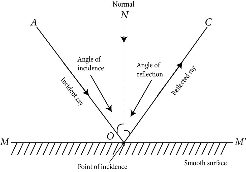
Reflection of light is the phenomenon of light rays bouncing back in the same medium after striking a smooth surface.
Reflection of Light
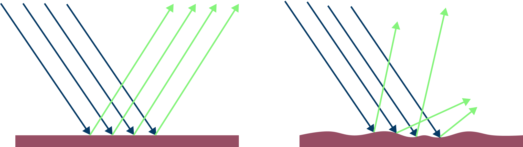
There are two types of reflection
Regular reflection: When light reflects off a very smooth surface and forms a clear image, this is referred to as regular reflection.
Irregular reflection: When a parallel light ray beam strikes a rough surface, the reflected rays scatter in various directions. This is referred to as irregular or diffuse reflection. Diffuse reflection refers to reflection from a rough surface.
Reflection
Laws of Reflection
There are two laws of reflection
The angle of incidence and reflection are always equal. i.e. $\angle i=\angle r$
At the point of incidence, the incident ray, reflected ray, and normal are all lie in the same plane.
Newton’s Corpuscular Theory
Light is made up of very small invisible elastic particles that travel at a speed of $3 \times 10^{8}$ in vacuum.
Reflection and refraction might be explained by the theory.
Distinct colours of light have different corpuscular sizes.
It could not account for interference, diffraction, or polarisation. Compton effect and photoelectric effect. The idea fell short because it failed to explain why light travels quicker in a rarer medium than in a denser one.
Wavefront
A wavefront is defined as the continuous locus of all medium particles vibrating in the same phase.
There are three kinds.
Spherical wavefront.
Cylindrical wavefront.
Plane wavefront.
Huygens’s Wave Theory
Light travels in a medium as a wave front.
A wave front is the intersection of all particles vibrating in the same phase.
Every particle on a wave front acts as a secondary light source, emitting secondary wavelets.
The envelope of secondary wavelets represents a wave front’s new position.
When the light source is a point source, the wave front is spherical.
Amplitude (A) is proportional to distance. (x) i.g., A $\propto 1 / x$
$\therefore$ Intensity $(\mathrm{I}) \propto(\text { Amplitude })^{2}$
When the light source is linear, the wavefront is cylindrical.
Amplitude (A) $\propto 1 / \sqrt{x}$
$\therefore$ Intensity $\propto(\text { Amplitude })^{2} \propto 1 / \mathrm{x}$
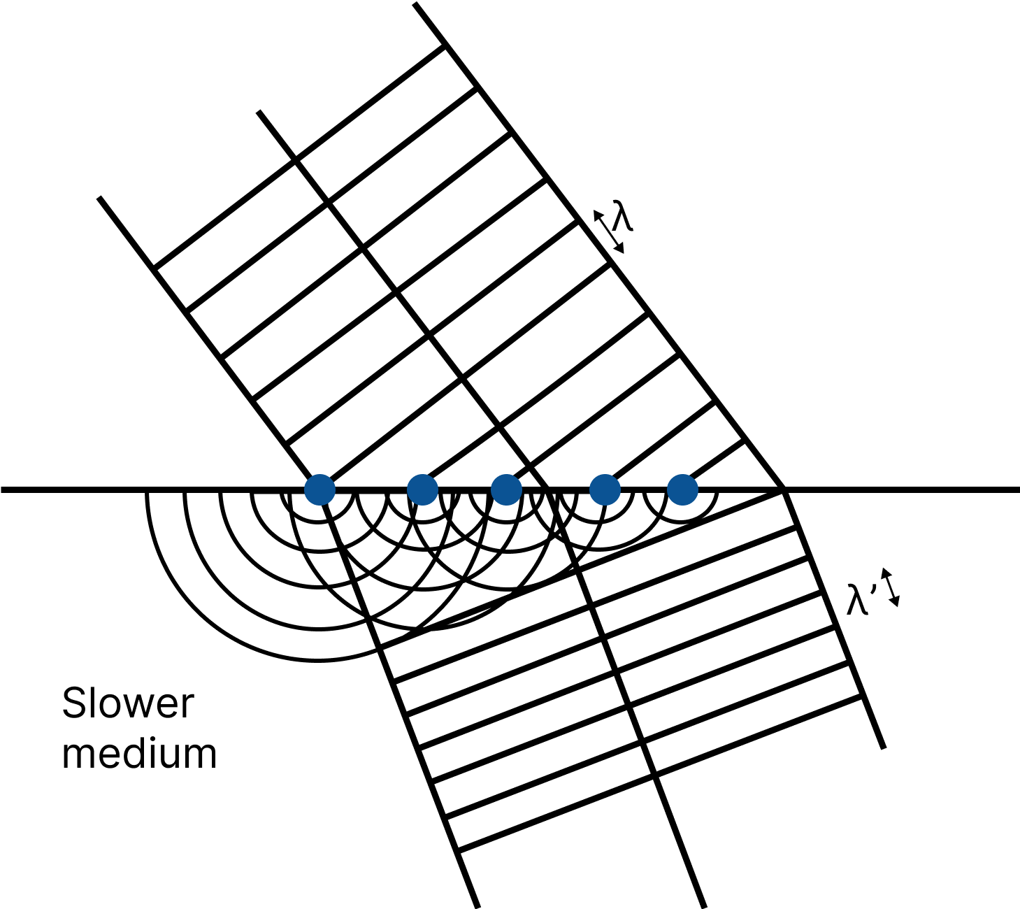
Huygens’s Principle
Each point on a particular wavefront (called the primary wavefront) operates as a new source of secondary wavelets.
The secondary wavelets travel at the speed of light in all directions in the medium.
At any instant, a surface that touches these secondary wavelets tangentially in the forward direction yields the new (secondary) wave front of that instant. Each point on a particular wavefront (called the primary wavefront) operates as a new source of secondary wavelets.
Huygens’s Principle
The secondary wavelets travel at the speed of light in all directions in the medium.
At any instant, a surface that touches these secondary wavelets tangentially in the forward direction
Yields The New (secondary) Wave Front of That Instant.
Each point on a certain wavefront (referred to as the primary wavefront) serves as a fresh source of secondary wavelets.
In the medium, secondary wavelets travel at the speed of light in all directions.
At any instant, a surface that tangentially encounters these secondary wavelets in the forward direction provides the new (secondary) wave front of that instant. $c=1 / \sqrt{\mu_{o}} \varepsilon_{\mathrm{o}}$
The velocity of electromagnetic waves in a medium is lower than the velocity of light.
$\mathrm{v}<\mathrm{c}$
$\mathrm{v}=1 / \sqrt{\mu_{\mathrm{o}}} \varepsilon_{\mathrm{o}} \varepsilon_{\mathrm{r}} \mu_{\mathrm{r}}=\mathrm{c} / \sqrt{\mu_{\mathrm{o}}} \varepsilon_{\mathrm{r}}$
Where $\mu_{\mathrm{o}}=$ absolute magnetic permeability and $\varepsilon_{o}=$ absolute electrical permittivity of free space.
The velocity of electromagnetic waves in a medium is determined by the medium's electric and magnetic characteristics.
It failed to explain the photoelectric effect, the Compton effect, and the Raman effect.
Reflection from Plane Mirror
The size of the image in a plane mirror is always equal to the size of the object, and it is virtual.
In a plane mirror, the image appears to be as far behind the mirror as the object in front of it.
Important Points Related to Simple Mirror are Given Below
When an object moves a distance towards or away from a mirror, its image moves a distance towards or away from the mirror.
The minimum mirror size required to see the full image of an observer is half the observer's height.
When the plane mirror is rotated in the plane of incidence by an angle $\theta$, then the reflected ray rotates by an angle $2 \theta .$
The focal length of a plane mirror is infinite, implying that its power is nil. The plane mirror produces a linear magnification of 1.
If two plane mirrors are kept facing each other at an angle $\theta$ and an object is placed between them, then number of images, $n=\dfrac{360^{\circ}}{\theta}-1$, if $\dfrac{360^{\circ}}{\theta}$ is even or the object lies symmetrically. Number of images, $n=\left(\dfrac{360^{\circ}}{\theta}\right)$, if $\dfrac{360^{\circ}}{\theta}$ is odd or the object lies asymmetrically.
There are an infinite number of images when two plane mirrors are parallel to each other.
The plane mirror is used in kaleidoscopes, periscopes, and looking glasses, among other things.
Spherical Mirror
The mirror is referred to as a spherical mirror if the reflecting surface is curved inwards or outwards.
Spherical Mirrors are of Two Types
Concave mirror: Concave mirrors are spherical mirrors with an inwardly curved reflecting surface. Because a beam of light converges after reflection from its surface, it is also known as a convergent mirror. e.g. A concave mirror can be thought of as the inner curved surface of a shining spoon.
Concave Mirror
Convex mirror: Convex mirrors are spherical mirrors with an outwardly curved reflecting surface. Because a beam of light diverges after reflection from its surface, it is also known as a divergent mirror. e.g. A shining spoon's outer curved surface can be treated or thought of as a convex mirror.
Convex Mirror
Some Definitions Related to Spherical Mirrors
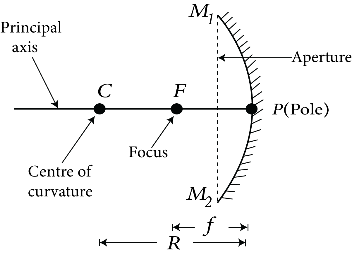
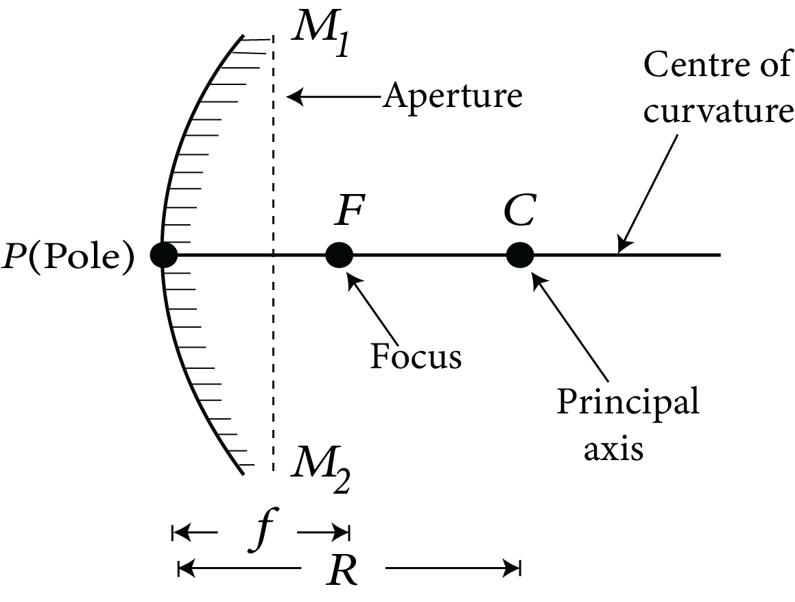
Centre of Curvature: The centre of curvature of a spherical mirror is the centre of the sphere from which it is separated. In the above figures, it is marked by $C$.
Radius of Curvature: A spherical mirror's radius of curvature is the radius of the sphere from which the mirror is separated. In the above figure, it is shown by $R$.
Pole: The spherical mirror's pole is the midpoint of its reflecting surface. In the figure, it is shown by $P$.
Principal Axis: The line connecting the pole and the centre of curvature is the principal axis of a spherical mirror. In the figure, PC is the principal axis.
Aperture of Mirror: The aperture of a mirror refers to the portion of the reflecting surface that can be exposed to incident light.
Principal Focus or Focus: After reflection, the light rays coming parallel to the principal axis actually meet or appear to be coming from this point on the principal axis of the mirror. It is represented by $F$. The focus of a concave mirror is in front of the mirror, whereas the focus of a convex mirror is behind the mirror. A concave mirror's focus is real, whereas a convex mirror's focus is virtual.
Focal Length: The focal length of a spherical mirror is the distance between the pole and the focus. It is represented by $f$.
Plane mirrors have an infinite focal length.
The curvature radius of a plane mirror is infinite.
Max Planck’s Quantum Theory
Light emits from a source in the form of quanta or photons, which are energy packets.
A photon's energy equals E = hv, where h is Planck's constant and v is light frequency.
Quantum theory can explain photoelectric, Compton, and Raman effects.
Quantum theory fails to explain light interference, diffraction, and polarisation.
De – Broglie’s Dual Theory
Light waves have a dual nature, one as a wave according to Maxwell's electromagnetic wave theory and one as a particle according to Maxwell's quantum theory.
The two natures of light are analogous to the two faces of a coin. Only one nature shows in any phenomenon.
Photon energy $=\mathrm{hv}=\mathrm{hc} / \lambda$
where, $\mathrm{h}=$ Planck's constant $6.6 \times 10^{-34} \mathrm{~J} / \mathrm{s}$
The de-Broglie wave equation is $\lambda=\mathrm{h} / \mathrm{p}=\mathrm{h} / \mathrm{mv}$ where h denotes Planck’s constant.
Superposition of Waves
When two comparable waves propagate in a medium at the same time, the resulting displacement is equal to the vector sum of the displacements produced by the separate waves at any point.$\mathrm{y}=\mathrm{y}_{1}+\mathrm{y}_{2}$
Interference of Light
When two light waves of equal frequency with a zero or constant phase difference propagate in the same direction in a medium at the same time, their superposition results in maximum intensity at some spots and minimum intensity at others.
This phenomenon of energy redistribution caused by wave superposition is known as interference of light waves.
Constructive interference refers to interference that occurs at maximum intensity points.
The interference that occurs at low intensity sites is called destructive interference.
Fringe Width
The fringe width is the distance between the centres of two successive bright or dark fringes.
The angular fringe width is given by $\theta=\lambda / \mathrm{d}$
where d is the distance between two coherent sources and is the wavelength of light
Conditions for Constructive and Destructive Interference
For Constructive Interference
Phase difference, $\varphi=2 n \pi$
Path difference, $\Delta \mathrm{x}=\mathrm{n} \lambda$
where, $\mathrm{n}=0,1,2,3, \ldots$
For Destructive Interference
Phase difference $\varphi=(2 n-1) \pi$
Path difference, $\Delta \mathrm{x}=(2 \mathrm{n}-1) \pi / 2$
where, $\mathrm{n}=1,2,3, \ldots$
If two waves of the same frequency and amplitude a and b collide, the amplitude of the resulting wave is given by
$\mathrm{R}=\sqrt{\mathrm{a}^{2}+\mathrm{b}^{2}+2 \mathrm{ab} \cos \varphi}$
where φ is the phase difference between two waves.
$R_{\max }=(a+b)$
$R_{\min }=(a-b)$
Young's Double Slit Experiment:
In fact, Young's initial double-slit studies were the first to establish interference. When Young flashed light through two small slits and viewed the pattern formed on a distant screen, he saw brilliant and dark fringes rather than two bright areas matching the apertures.
Derivation of Young’s Double Slit Experiment:
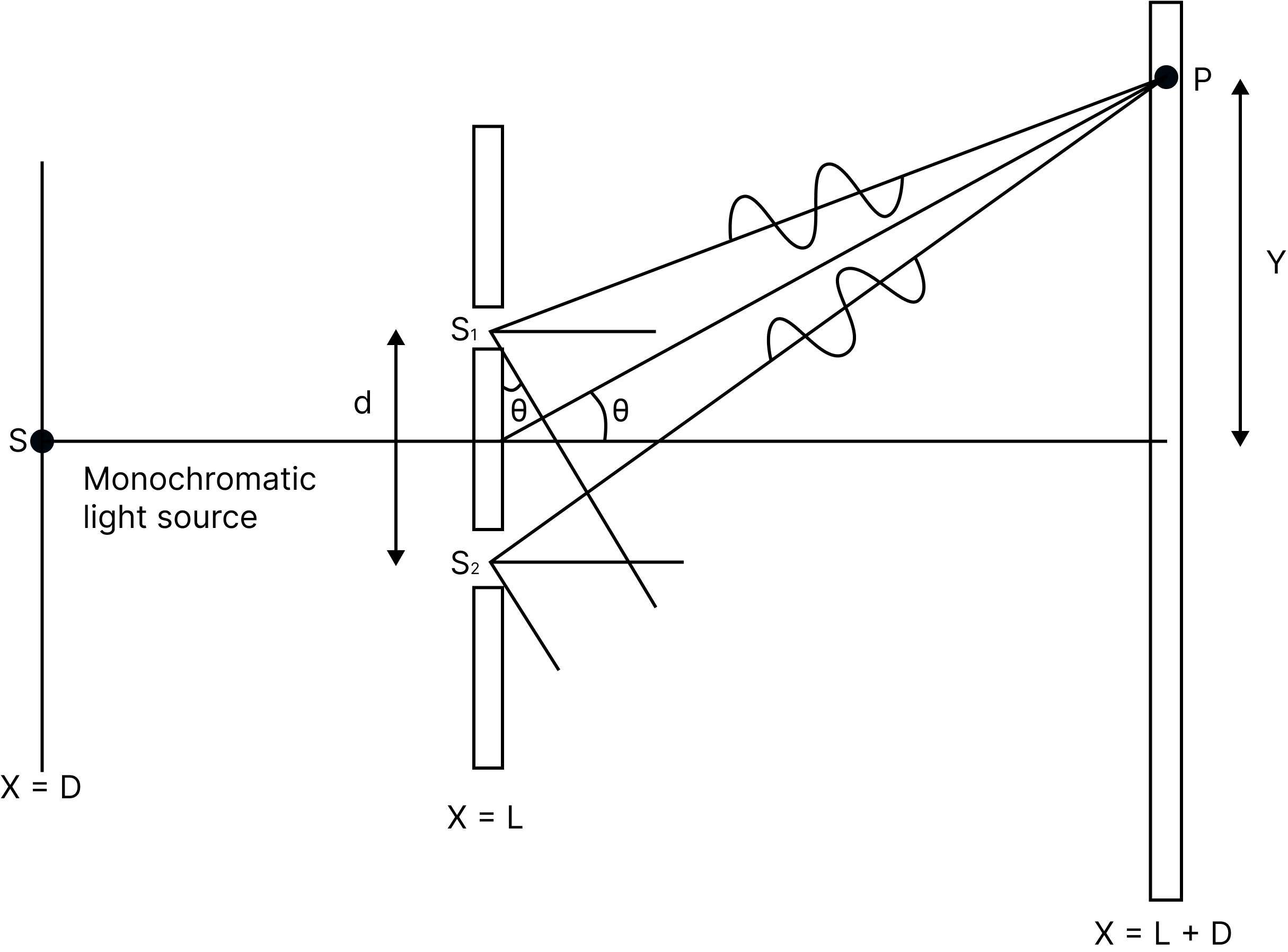
Consider a monochromatic light source ' $S$ ' placed at a significant distance from two slits $s_{1}$ and $s_{2} . S$ is located between $s_{1}$ and $s_{2}$. Because they are both generated from $S, s_{1}$ and $\mathrm{s}_{2}$ act as two coherent sources.
The light goes through these holes and lands on a screen located 'D' away from the positions of slits $s_{1}$ and $s_{2}$. ' $d$ ' is the distance between two slits.
If $s_{1}$ is open and $s_{2}$ is closed, the screen opposite $s_{1}$ is darkened, and only the screen opposite $s_{2}$ is lit. Only when both slits $s_{1}$ and $s_{2}$ are open do the interference patterns occur.
Young’s Double Slit Experiment
When the slit spacing (d) and screen distance (D) remain constant, light waves from $\mathrm{s}_{1}$ and $s_{2}$ must travel different lengths to reach $P$. It suggests that there is a route difference between the two light waves from $s_{1}$ and $s_{2}$ in Young's double slit experiment.
Approximations in Young’s Double Slit Experiment
Approximation 1:D > > d: Since D > > d, the two light rays are assumed to be parallel.
Approximation 2: d/λ >> 1: Often, d is a fraction of a millimetre and λ is a fraction of a micrometre for visible light
Under these conditions $\theta$ is small, thus we can use the approximation $\sin \theta=\tan \theta \approx \theta=N / d$.
$\therefore$ path difference, $\Delta \mathrm{z}=\lambda / \mathrm{d}$
This is the path difference between two waves meeting at a point on the screen. Due to this path difference in Young's double-slit experiment, some points on the screen are bright and some points are dark.
The approximation $\sin \theta=\tan \theta \approx \theta=N / d$ can be used when $\theta$ is small under certain circumstances. As a result, the path difference is $\Delta \mathrm{z}=\lambda / \mathrm{d}$
This is the difference in the paths taken by two waves that collided on the screen. In Young's double-slit experiment, certain places on the screen are bright while others are black due to this path difference.
Position of Bright Fringes:
$x=n \lambda D / d$
The distance of the $\mathrm{n}^{\text {th }}$ bright fringe from the centre is
$\mathrm{x}_{\mathrm{n}}=\mathrm{n} \lambda \mathrm{D} / \mathrm{d}$
Similarly, the distance of the $(n-1)^{\text {th }}$ bright fringe from the centre is
$x_{(n-1)}=(n-1) \lambda D / d$
Fringe width, $\beta=x_{n}-x_{(n-1)}=n \lambda D / d-(n-1) \lambda D / d=\lambda D / d$
$(n=0, \pm 1, \pm 2, \ldots)$.
Fringe Width:
The fringe width is the distance between two adjacent bright (or dark) fringes.
$\beta=\lambda D / d$
Angular Width of Fringes:
$\theta=\dfrac{\lambda}{d}=\dfrac{\beta}{D}$
Angular width is independent of ' $n$ ' i.e angular width of all fringes are the same.
Intensity of wave
$\therefore \mathrm{I}=\mathrm{a}^{2}+\mathrm{b}^{2}+2 \mathrm{ab} \cos \varphi$
$=\mathrm{I}_{1}+\mathrm{I}_{2}+2 \sqrt{\mathrm{I}}_{1} \mathrm{I}_{2} \cos \varphi$
where $\mathrm{I}_{1}$ and $\mathrm{I}_{2}$ are the intensities of two waves.
$\therefore \mathrm{I}_{1} / \mathrm{I}_{2}=\mathrm{a}^{2} / \mathrm{b}^{2}=\omega_{1} / \omega_{2}$
Where $\omega_{1}$ and $\omega_{2}$ are the width of slits.
Energy remains conserved during interference. Interference fringe width
$\beta=\mathrm{D} \lambda / \mathrm{d}$
where, D = distance of screen from slits, λ = wavelength of light and d = distance between two slits.
Distance of nth bright fringe from central fringe $\mathrm{x}_{\mathrm{n}}=\mathrm{nD} \lambda / \mathrm{d}$
Distance of nth dark fringe from central fringe $x_{n}^{\prime}=(2 n-1) D \lambda / 2 d$
Coherent Sources of Light
Coherent sources of light are those that emit light of the same wavelength and frequency with a zero or constant phase difference.
When a transparent sheet of refractive index and thickness t is inserted into one of the paths of interfering waves, the fringe pattern moves by Y in that direction.$Y=D / d(\mu-1) t=\beta / \lambda(\mu-1) t$ where, β = fringe width.
Fresnel’s Biprism
It is made up of two prisms with very modest refracting angles that are arranged base to base. It generates two coherent sources from a single light source.
Lyod’s Mirror
Interference fringes are typically hyperbolic in shape.
The fringes are circular when the screen is held at 900 to the line connecting the hyperbola's foci.
When the screen distance (D) is much more than the distance between the slits (d), the Cringes are straight.
Diffraction
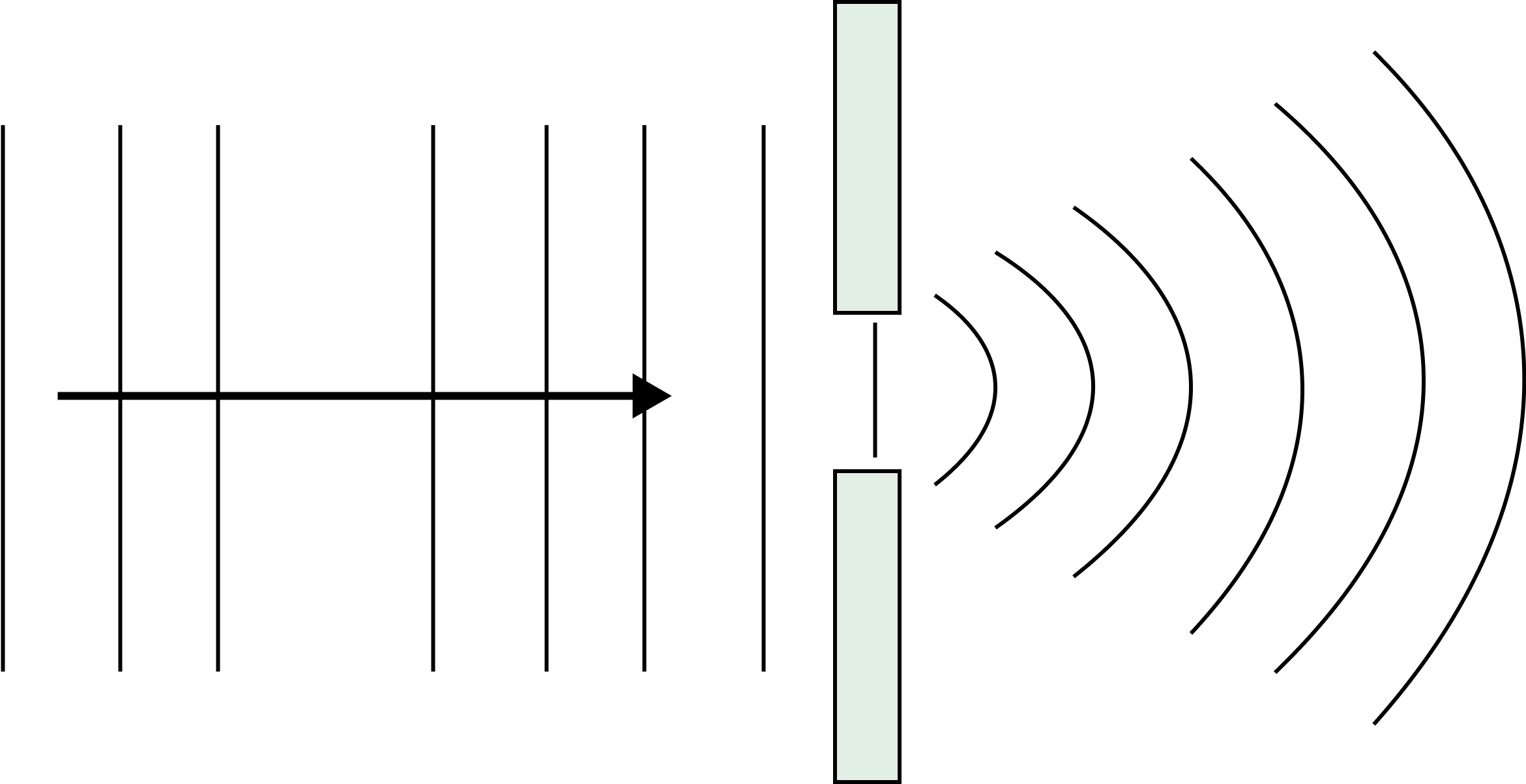
Diffraction
Diffraction of light is the bending of light waves around the corners of an obstruction or aperture.
The phenomena of diffraction is classified primarily into two types.
Fresnel class.
Fraunhofer class.
Fraunhofer Diffraction at a Single Slit
Linear Width 0f central maximum $2 \mathrm{D} \lambda / \mathrm{a}=2 \mathrm{f} \lambda / \mathrm{a}$
Angular width of central maximum $=2 \lambda / \mathrm{a}$
where, λ = wavelength of light, a = width of single slit, D = distance of screen from the slit and f = focal length of convex lens.
For Secondary Minima
Path difference $=n \lambda$
Linear distance $=nD \lambda / a= nf \lambda / a$
Angular spread $=\mathrm{n} \lambda / \mathrm{a}$ where, $\mathrm{n}=1,2,3, .$,
For Secondary Maxima
Path difference $=\left( \mathbf{2}\text{ }\mathbf{n}+\mathbf{1} \right)\dfrac{\lambda }{2}$
Linear distance $=(2n+1)\text{D}\lambda /2\text{a}=(2n+1)\text{f}\lambda /2\text{a}$
Angular spread $=\left( \mathbf{2}\text{ }\mathbf{n}+\mathbf{1}\right)\lambda /\text{2}$ where, $\mathrm{n}=1,2,3, .$,
Important Points
Because of the interference of light reflected from the upper and lower surfaces of the soap bubble or oil film, a soap bubble or oil film on water appears coloured in white light.
All bright and dark fringes in an interference fringe pattern are the same width; in a diffraction fringe pattern, the central bright fringe is the brightest and whitest. The remaining secondary maximas are gradually decreasing in intensity.
The distinction between interference and diffraction is that interference is the superposition of wavelets from two coherent sources, whereas diffraction is the superposition of wavelets from a single wavefront.
Polarisation
Polarisation is the phenomenon of the reorganisation of electric vectors of light into a single direction.
Ordinary light has electric vectors pointing in all feasible directions in a plane perpendicular to the light's propagation direction.
When conventional light passes through a tourmaline, calcite, or quartz crystal, the transmitted light has electric vectors that run parallel to the crystal's axis. This light has a plane polarisation.
A plane of vibration is a plane that contains the vibrations of polarised light.
The plane of polarisation is a plane perpendicular to the plane of vibration.
Polarisation can only occur in transverse waves.
Nicol Prism
A nicol prism is an optical device used for producing plane polarised light and analysing it.
The nicol prism is made out of two calcite crystals cut at 68° and bonded together using a glue called Canada balsam.
Law of Malus
When a perfectly plane polarised light beam strikes an analyser, the intensity of the transmitted light is directly proportional to the square of the cosine of the angle between the plane of transmission of the analyser and the polariser, i.e.$I \propto \cos ^{2} \theta$
When conventional light strikes a polariser, the intensity of the transmitted light is half that of the incident light.
When a polariser and an analyser are perpendicular to each other, the intensity of the light transmitted by the analyser becomes O.
Brewster’s Law
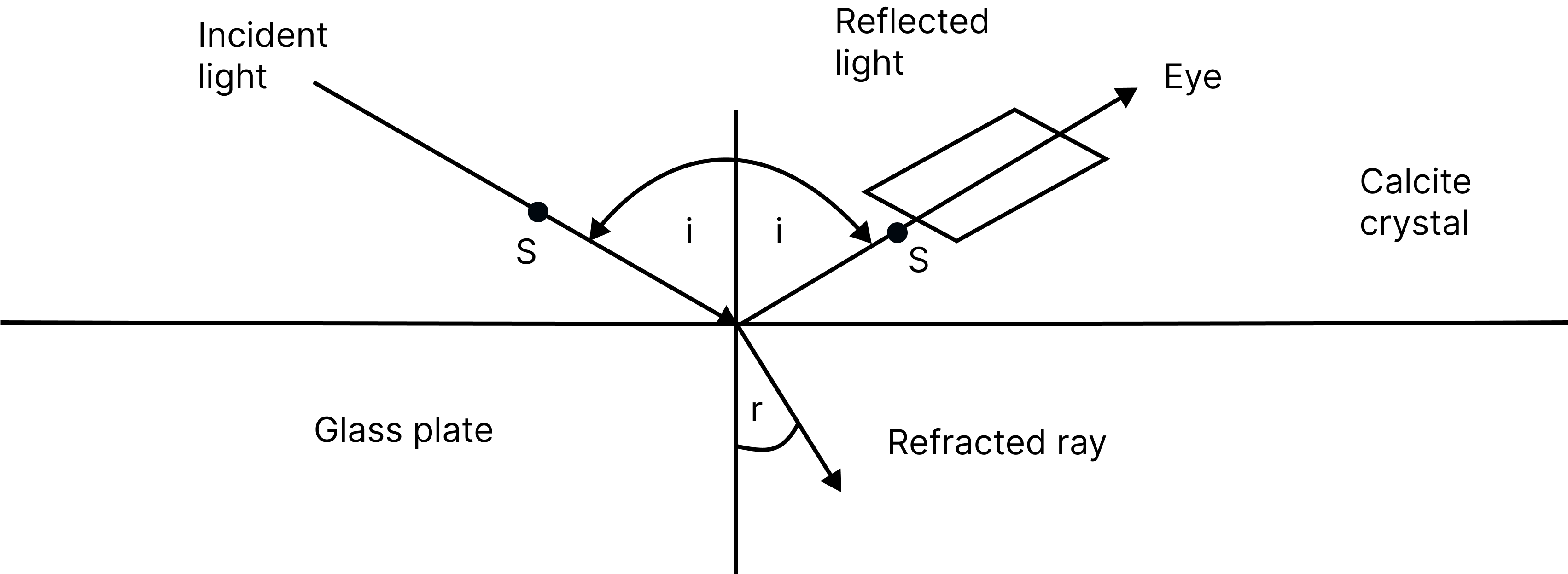
Brewster’s Law
When unpolarised light is incident at an angle of polarisation (ip) on the interface separating air from a medium with a refractive index, the reflected light becomes fully polarised, assuming that the incident light is incident at an angle of polarisation (ip).
$\mu=\tan \mathrm{i}_{\mathrm{p}}$
If angle of polarisation is $\mathrm{i}_{\mathrm{p}}$ and angle of refraction is $\mu$ then
$\mathrm{i}_{\mathrm{p}}+\mathrm{r}=90^{\circ}$
Refractive index $\mu=\tan i_{p}=1 / \sin C$
where, $\mathrm{C}=$ critical angle.
Double Refraction
When unpolarized light strikes a calcite or quartz crystal, it divides into two refracted beams. One of which obeys refraction principles. Ordinary rays (O-rays) and others do not obey refraction laws. referred to as exceptional ray (E-ray). This is known as twofold refraction.
Dichroism
Few double-refracting crystals have the ability to absorb one of the two refracted rays while permitting the other to emerge. Dichroism is the name given to this feature of crystal.
Polaroid
It consists of a polarising film sandwiched between two glass plates. It is used to generate polarised light.
A polaroid is used to avoid light glare in eyewear.
Uses of Polaroid
Polaroids are used in the manufacture of sunglasses. They provide glare protection for the eyes.
Polaroids are employed in trains and, notably, aeroplane window panes. They aid in controlling the amount of light that enters through the window.
Images captured by a stereoscopic camera. When viewed with polarised spectacles, it creates a three-dimensional impression.
A polaroid windshield is used in automobiles. This type of mental barrier shields the driver's eyes from the dazzling light of approaching automobiles.
Formula Chart:
Example 1: In a Young's double slit experiment, an angular width of the fringe is $0.35^{\circ}$ on a screen placed at $2 \mathrm{~m}$ away for particular wavelength of $450 \mathrm{~nm}$. The angular width of the fringe, when the whole system is immersed in a medium of refractive index $7 / 5$, is $\dfrac{1}{\alpha}$. The value of $\alpha$ is
1
4
3
2
Answer:(B)
Examination:
Angular fringe width $\theta=\dfrac{\lambda}{D}$
So $\dfrac{\theta_{1}}{\lambda_{1}}=\dfrac{\theta_{2}}{\lambda_{2}}$
$\theta_{2}=\dfrac{0.35^{\circ}}{450 \mathrm{~nm}} \times \dfrac{450 \mathrm{~nm}}{715}=0.25^{\circ}=\dfrac{1}{4}$
So $\alpha=4$
Hence, the value of $\alpha$ is 4.
Example 2: The width of one of the two slits in a Young's double slit experiment is three times the other slit. If the amplitude of the light coming from a slit is proportional to the slit-width, the ratio of minimum to maximum intensity in the interference pattern is $x: 4$ where $x$ is
3
4
1
2
Answer:(C)
Examination:
Given, $b_{1}=3 b_{2}$
Here, $b_{1}=$ width of one of the two slits and $b_{2}=$ width of the other slit.
As we know that,
Intensity, I $\propto(\text { Amplitude })^{2}$
$\Rightarrow \dfrac{I_{1}}{I_{2}}=\left(\dfrac{b_{1}}{b_{2}}\right)^{2}$
$\Rightarrow \dfrac{I_{1}}{I_{2}}=\left(\dfrac{3 b_{2}}{b_{2}}\right)^{2}$
$I_{1}=9 I_{2}$
As we know, the ratio of the minimum intensity to the maximum intensity in the interference pattern,
$\dfrac{I_{\min }}{I_{\max }}=\left(\dfrac{\sqrt{I_{1}}-\sqrt{I_{2}}}{\sqrt{I_{1}}+\sqrt{I_{2}}}\right)^{2}$
Substituting the values in the above equations, we get
$\dfrac{I_{\min }}{I_{\max }}=\dfrac{\left(\sqrt{9 I_{2}}-\sqrt{I_{2}}\right)^{2}}{\left(\sqrt{9 I_{2}}+\sqrt{I_{2}}\right)^{2}}=\left(\dfrac{3-1}{3+1}\right)^{2}$
$\dfrac{I_{\min }}{I_{\max }}=\dfrac{1}{4}$
Comparing with, $\dfrac{I_{\min }}{I_{\max }}=\dfrac{x}{4}$
The value of $x=1$.
Common Errors or Mistakes that Should be Avoided by the Students Keeping the Exam Point of View:
Students forget to write the working formula.
Students also write improper units without checking their compatibility.
Calculation errors when doing problems
Students forget to put in the correct data they used in the working formula, which is used by teachers to check how effective the students' learning is.
A law stated by someone cannot be restructured, it should be reiterated like how it was stated.
Read important topics like , Incoherent and coherent waves addition, reflection and refraction of plane waves using the Huygen principle, interference and Young's double-slit experiment, diffraction of light, polarisation by scattering and resolving power of optical Instruments.
For questions which require the reason for a certain condition, firstly students are required to state the cause of the condition and then the consequence of the condition.
Importance of Class 12 Physics Wave Optics for NEET
This chapter introduces students to the wave nature of a light ray. According to Huygens’s principles, students will find out that light rays behave like a wave. The locations of the particles at any instant can be explained by using this principle. Students will learn how these terms are defined and mathematically represented. They will learn the meaning of phase speed, wavefront, frequency, wavelength, etc.
This chapter will also explain how Huygens’ theory explains and verifies the natural phenomenon of polarisation, diffraction, reflection, refraction, and interference. It explains how wavelength is inversely proportional to the refractive index of a transparent medium.
The laws of reflection and refraction studied by the students will be explained on the basis of this principle. Proper pictorial illustration and theoretical explanation will be given according to this theory to establish the natural phenomenon of refraction of light.
This chapter holds immense importance in Class 12 Physics NEET syllabus as it teaches students the particle and wave nature of light rays using this principle. They will be introduced to advanced concepts of superposition, interference, and the principles behind optical instruments such as microscopes, telescopes, etc. To make the revision of this chapter simpler, you can refer to the Wave Optics important notes prepared by the subject experts.
Benefits of Vedantu’s Wave Optics Revision Notes PDF for NEET Exam
These revision notes have been composed with the prime aim of consolidating the scientific information given in this chapter in a simpler format. This format will guide you to remember the concepts, theories, principles, definitions, and derivations of formulae without any difficulty.
You will not have to go through the elaborate chapter for revision before an exam when you have these notes to guide you. The concise format will help you progress through the chapter in a methodical way.
The easier format will also help you memorise the formulas and derivations of all the scientific terms related to wave optics faster. You will also be able to recall these formulas during an exam and answer questions accurately.
Find out how the experts have answered the Wave Optics NEET questions given as samples in these notes. Check how the experts have correlated the concepts and answered them efficiently.
Download Wave Optics Class 12 Revision Notes PDF
Remembering and revising Wave Optics have never been easier without proper revision. Download the free PDF version of Wave Optics notes for NEET and make revision sessions of this chapter more productive. Reduce your preparation time by checking the simplest explanations of all scientific terms and formulae in these notes. Gain confidence by easily memorising the principles and formulae of wave optics with the help of these notes.
Other Important Links
NEET Physics Revision Notes - Chapter Pages

FAQs on NEET Revision Notes for Physics Wave Optics
1. What happens to wave energy when a light ray enters a glass from air?
When a light ray enters a glass from air, a part of it is reflected back to the air. It means its wave energy will be lower while travelling in the glass.
2. What happens to the frequency of a light ray when it enters glass from air?
The frequency of a light ray remains unchanged when it enters a glass from air.
3. What is the principle of superposition?
When two or more rays superimpose, their magnitudes are amplified resulting in a higher amplitude due to a higher displacement of the wave particles.
4. What is phase difference?
The difference between the phase angles of two waves is called phase difference.