NEET 2026 Revision Notes for Physics Current Electricity - Free PDF Download
Current Electricity is one of the most important chapters of the Class 12 NEET syllabus offering precise and in-depth knowledge about electricity, electric charges, electric potential, electric resistance, etc. The relevant terms to current electricity and the scientific principles will be explained in this chapter. Students will also find the derivation of definitions, laws, and principles using mathematical tools. The concepts will teach the different terminologies used in current electricity. To make it easier for the students, the subject experts of Vedantu have prepared Current Electricity Class 12 notes.
These notes are composed to offer an easier medium to comprehend all the concepts of this chapter. Students will gain from the convenience of referring to these concise notes by reducing their preparation time to a considerable extent.
NEET Physics Revision Notes - Chapter Pages
NEET Physics Chapter-wise Revision Notes | |
Current Electricity Notes | |
Access NEET Revision Notes Physics Current Electricity
Electric Current:
Electric current is defined as the amount of charge flowing through a specific area per unit time.
It is the rate at which electric charges flow.
When a net charge Q, flows across any cross-section of a conductor in time t, then the current I, through the cross-section is - I = \[ \frac{Q}{t} \] .
We know that, The SI unit of electric charge is the coulomb (c), which is equivalent to the charge contained in nearly: 6 x 10¹⁸ electrons
An ampere is a unit of measurement for electric current (A).
One ampere is the flow of one coulomb of charge per second that is, 1A = 1C/1s.
Types of Electric Current:
Direct Current (DC): In DC, all the electrons move in the same direction, in all the time that the electricity flows.
Example: Current produced by the batteries in torches.
Alternating Current (AC): In AC, the direction of the motion of electron changes with time.
Example: Power supply in house.
Electric Potential and Potential Difference
The amount of work required to move a unit charge from a reference point to a specific point in an electric field is known as electric potential. The reference point is usually Earth, but any point outside of the electric field charge's influence can be used.
The work done to move a unit charge from one point to the other is the electric potential difference between two points in an electric circuit carrying some current.
Potential difference (V) between two points = \[ \frac{Work \ done (W) }{Charge} \]
$\text{V} = \frac{W}{Q}$
We know that, The SI unit of electric potential difference is volt (V), named after Alessandro Volta (1745–1827), an Italian physicist.
A volt is the potential difference between two points in a current-carrying conductor when one joule of work is performed to move a charge of one coulomb from one point to the other.
The potential difference is measured using a device known as a voltmeter.
The voltmeter is always connected in parallel across the points to be measured for potential difference.
Electric Currents in Conductors
Some electrons in other materials, particularly metals, are practically free to move within the bulk material.
When an electric field is applied to these materials, which are commonly referred to as conductors, they generate electric currents.
In Solid Conductors:
In the absence of an electric field, the number of electrons travelling in any direction is equal to the number of electrons travelling in the opposite direction. As a result, there will be no net electrical current.
When an electric field is applied, an electric field is created that is directed from the positive to the negative charge.
As long as the electrons are moving, they will form an electric current.
Current Density:
Current density is a vector quantity defined as the current per unit area through an infinitesimal area normal to the direction of current flow.
Drift Velocity:
When an electric field is applied in a conductor, a force acts on each electron in the direction opposite to that of the field. The electrons start random motion. As a result, the electrons drift slowly in that direction.
Drift velocity, $v = \dfrac{{Ee\tau }}{{2m}}$
τ : average time interval between two successive collisions
E : electric field
e : charge on an electron
m : the mass of an electron.
Therefore,
Current, $i = nAve$
Current density, $j = \dfrac{i}{A} = nve$
Ohm’s Law:
If the physical conditions of conductor (temperature, length etc.) remain constant, then the current in the conductor is directly proportional to the potential difference across the conductor.
Consider a conductor through which current I flow, and let V be the potential difference between the conductor's ends.
According to Ohm's law : \[V\propto I\]
Or, \[V\text{ }=\text{ }R\text{ }I;\]
Here the constant of proportionality R is called the resistance of the conductor. The SI units of resistance is ohm, and is denoted by the symbol Ω.
The Resistance of the Conductor Depends-
The resistance of the conductor depends upon the temperature of the conductor.
The resistance of the conductor depends upon the cross-sectional area of the conductor.
The resistance of the conductor depends upon the length of the conductor.
The resistance of the conductor depends upon the nature of the material of the conductor.
We know that, Electrical resistance is directly proportional to the length $(\text{L})$ of the conductor and inversely proportional to the cross-sectional area (A).
$\text{R}=\rho l/\text{A}$ , Here $\rho $ is the resistivity of the material (measured in $\Omega m$, ohm meter)
Resistivity is a qualitative measurement of a material's ability to resist flowing electric current. Obviously, insulators will have a higher value of resistivity than of conductors.
Limitations of Ohm’s Law
Ohm's law does not apply to unilateral electrical elements such as diodes and transistors because they only allow current to flow in one direction.
Voltage and current will not be constant with respect to time for non-linear electrical elements with parameters such as capacitance, resistance, and so on, making Ohm's law difficult to apply.
Ohmic and non-ohmic Conductor:
When the current or voltage is reversed, the magnitude of the current remains constant. The voltage determines the current. Current and resistance are affected by temperature.
When the current or voltage is reversed, the magnitude of the current remains change. The voltage has no effect on the current. Light and temperature are two of the many factors that influence it.
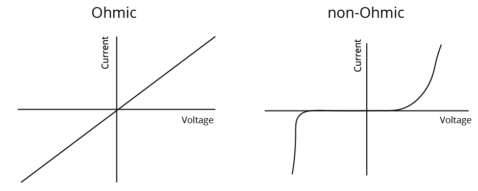
Ohmic and Non-Ohmic Conductor
The Electrical Resistivity of a Material:
Electrical resistivity is a feature that is unique to each material and must be understood before developing and building electrical and electronic systems. Understanding how materials differ in resistivity allows for the selection of acceptable materials for motors, electrical circuits, dielectrics, resistive heating, and superconducting applications.
The resistance of a uniform metallic conductor is proportional to its length (l) and inversely proportional to its cross-sectional area (A).That is,
$R\propto l$ and
$\text{R}\propto \dfrac{1}{A}$
Combining both, we get
$\text{R}\propto \dfrac{l}{A}$
$\text{or, R}=\rho \dfrac{l}{A}$.
Here ρ (rho) is a constant of proportionality and is called the electrical resistivity of the material of the conductor.
The SI unit of resistivity is Ω m.
It is a distinguishing feature of the material.
Variation of Resistance with Temperature:
The resistance of any material is proportional to its resistivity, which varies with temperature. Therefore, resistance also varies with temperature.
A material's resistivity is discovered to be temperature dependent.
An alloy's resistivity is generally greater than that of its constituent metals. At high temperatures, alloys do not oxidise (burn).
As a result, they are commonly used in electrical heating devices such as electric irons and toasters.
Tungsten is almost exclusively used for electric bulb filaments, whereas copper and aluminium are commonly used for electrical transmission lines.
Some materials, such as Chrome (a nickel, iron, and chromium alloy), have a very weak temperature dependence of resistivity.
${R_t} = {R_0}(1 + \alpha t + \beta {t^2})$, where t is the temperature
For small temperature, ${R_t} = {R_0}(1 + \alpha t)$
Combination of Resistances:
Series Combination: $R = {R_1} + {R_2}$
Parallel Combination: $\dfrac{1}{R} = \dfrac{1}{{{R_1}}} + \dfrac{1}{{{R_2}}}$
Two Major Types of Resistors:
Wire bound resistors: These are created by winding wires of an alloy, such as manganic, constantan, chrome, or a similar alloy.
The selection of these materials is primarily influenced by the fact that their resistivity are relatively insensitive to temperature.
These resistances are typically in the range of a few hundred ohms to a fraction of an ohm.
Carbon Resistors: The majority of resistors in the higher range are made of carbon. Carbon resistors are small and inexpensive, so they are widely used in electronic circuits.
Because carbon resistors are small in size, their values are represented by a color code.
Resistors Colour Code:
Many years ago, an international and globally acknowledged resistor colour code scheme was devised as a simple and rapid manner of identifying a resistor's ohmic value regardless of size or condition. It is made up of a series of distinct coloured rings or bands that are arranged in spectral order to represent each digit of the resistor's value.
The resistor colour code marks are always read one band at a time, from left to right, with the bigger width tolerance band oriented to the right side to indicate its tolerance. The first digit of the resistance value is recognised by matching the colour of the first band with its associated number in the digit column of the colour chart below.
Again, we get the second digit of the resistance value by matching the colour of the second band with its related number in the digit column of the colour chart, and so on. The resistor colour coding is then read from left to right, as seen below:
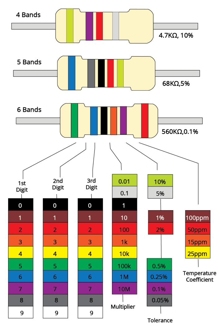
Color Code
The Resistor Colour Code Table:
Colour | Digit | Multiplier | Tolerance |
Black | 0 | 1 | |
Brown | 1 | 10 | $\pm 1 \%$ |
Red | 2 | 100 | $\pm 2 \%$ |
Orange | 3 | 1000 | |
Yellow | 4 | 10,000 | |
Green | 5 | 100,000 | $\pm 0.5 \%$ |
Blue | 6 | 1,000,000 | $\pm 0.25 \%$ |
Violet | 7 | 10,000,000 | $\pm 0.1 \%$ |
Grey | 8 | $\pm 0.05 \%$ | |
White | 9 | ||
Gold | 0.1 | $\pm 5 \%$ | |
Silver | 0.01 | $\pm 10 \%$ | |
None | $\pm 20 \%$ |
Relation of Current and Drift Velocity
When an electric field is applied, the path of an electron inside a conductor becomes curved (parabolic) instead of straight lines due to electric force, and electrons drift opposite to the field.
As a result of this drift, electrons' random motion is altered, and there is a net transfer of electrons across a cross-section, resulting in current.
Drift velocity is the average uniform velocity attained by free electrons inside a metal as a result of the application of an electric field that drives current through it.
Electrical Energy and Power
Electric power is the rate at which electric energy is dissipated or consumed in an electric circuit. P's power is given by
$P=VI$
Or $P={{I}^{2}}R={{V}^{2}}/R$
The watt is the SI unit of electric power (W).
It is the amount of power consumed by a device carrying 1 A of current when operated at a potential difference of 1 V. Thus,$1~\text{W}=1$ Volt $\times 1$ ampere $=1\text{VA}$
The commercial unit of electric energy is kilowatt-hour (kW h), commonly known as ‘unit’
Cells In Series and In Parallel
Cell: A cell is a device that generates electricity by utilizing chemical energy.
A cell consists of two electrodes, known as the positive (P) and negative (N), which is immersed in an electrolytic solution where the electrodes exchange charges with the electrolyte.
Current flows from cathode to anode via an external circuit;
Current flows from anode to cathode via the electrolyte.
EMF (Electromotive force):
It is defined as the potential difference between electrodes when there is no current in the cell.
Emf of the cell initiates the flow of current in the cell.
Internal Resistance:
It is the resistance provided by the electrolyte and electrodes as current flows. It is represented by the letter 'r.'
Cells in Series
A series combination occurs when multiple cells are arranged in such a way that the positive terminal of one cell is connected to the negative terminal of the next cell, and so on.
For two cells of emf's \[{{E}_{1}}\text{ }and\text{ }{{E}_{2}}\] connected in series with \[{{r}_{1}},\text{ }{{r}_{2}}\] as their internal resistances, E equivalent $={{E}_{1}}+{{E}_{2}}$
Equivalent $={{r}_{1}} + {{r}_{2}}$
The equivalent emf of a series combination of n cells is simply the sum of their individual emf's, and the equivalent internal resistance of a series combination of n cells is simply the sum of their internal resistances.
Cells in Parallel
Parallel combination occurs when cells are arranged in such a way that the positive terminals of all cells are connected together and the negative terminals of all cells are connected together.
For two cells of emf's \[{{E}_{1}}\text{ }and\text{ }{{E}_{2}}\] connected in parallel with \[{{r}_{1}},\text{ }{{r}_{2}}\] as their internal resistances, the formula is given as:
\[ \frac{1}{r} \] equivalent = \[ \frac{1}{{r}_{1}} + \frac{1}{{r}_{2}} \]
E equivalent/req = \[ \frac{{E}_{1}}{{r}_{1}} + \frac{{E}_{2}}{{r}_{2}} \]
Important Note:-
Cells are connected in series to increase voltage;
Cells are connected in parallel to increase current.
Potentiometer
It is essentially a long piece of uniform wire, sometimes several metres long, across which a standard cell is connected.
A variable resistance (rheostat, R) in the circuit controls the current I that flows through the wire.
Because the wire is uniform, the potential difference between A and any point $l$ from A is
$E(1)=\Phi l$Here $\Phi $ is the potential drop per unit length.
An application of the potentiometer is to compare the emf of two cells of emf ${{\varepsilon }_{1}}$ and ${{\varepsilon }_{2}}$ which is given by the equation:
$\dfrac{{{\text{E}}_{1}}}{{{\text{E}}_{2}}}=\dfrac{{{l}_{1}}}{{{l}_{2}}}$
The potentiometer has the advantage of drawing no current from the voltage source under test.
A potentiometer is also used to measure a cell's internal resistance.
Kirchhoff's Law:
First Law: The algebraic sum of currents at any junction is equal to zero.
Second Law: The algebraic sum of potential drop across all circuit elements in a closed loop is equal to zero.
Wheatstone Bridge:
It is a special type of network of resistances, commonly used for comparing resistances. It is used to find unknown resistance in terms of three known resistances. It consists of five resistances, of which four resistances are connected in the form of a bridge.
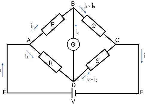
Wheatstone Bridge
For balanced bridge, no current flows through the galvanometer.
PS = RQ
If the positions of battery and the galvanometer are interchanged, then there will still be no deflection in the galvanometer.
Heating Effect of Current:
When an electric current is passed through a conductor, the conductor becomes hot after some time and produce heat. This happens due to the conversion of some electric energy passing through the conductor into heat energy. This effect of electric current is called heating effect of current.
The heating effect of current was studied experimentally by Joule (called Joule’s law) According to the law, the heat produced (H) in a conductor is directly proportional to the product of square of current (i), resistance of the conductor (R) and the time (t) for which current is passed. Thus,
$H = {i^2}Rt$
Electrical Energy and Power: The work done in pushing a charge round an electrical circuit is given by work done = $Vit$
So that power, $P = Vi$
Conductor:
A conductor is a substance that easily allows electric charges to pass through it.
A conductor has a very low resistance to the flow of current, such as copper, silver, or aluminum.
Insulator
An infinitely high resistance substance that does not allow electric current to flow through it.
It is referred to as an insulator.
For example, rubber, glass, plastic, Ebonite, and so on.
Coulomb’s Law:
Coulomb's law states that the attraction or repulsion force between two charged bodies is proportional to the product of their charges and inversely proportional to the square of their distance. It has an effect along the line that connects the two point charges.
Coulomb's Law Formula:
$F=\dfrac{1}{4\pi {{\varepsilon }_{0}}{{\varepsilon }_{r}}}\cdot \dfrac{{{\text{q}}_{1}}{{q}_{2}}}{{{d}^{2}}}=\dfrac{1}{4\pi {{\varepsilon }_{0}}K}\cdot \dfrac{{{\text{q}}_{1}}{{q}_{2}}}{{{d}^{2}}}$
$F=\dfrac{1}{4\pi \varepsilon }\cdot \dfrac{{{\text{q}}_{1}}{{q}_{2}}}{{{d}^{2}}}$
Here,$\varepsilon $ is absolute permittivity, $K$ or ${{\varepsilon }_{\text{r}}}$ is the relative permittivity or specific inductive capacity, ${{\varepsilon }_{0}}$ is the permittivity of free space, $K$ or ${{\varepsilon }_{r}}$ is also called a dielectric constant of the medium in which the two charges are placed.
Important Formulae:
Current I | \[\text{I} = \frac{Q}{t}\] Q = Charge $\text{t}=$ time taken |
Voltage V | V = \[ \frac{E}{Q}\] or V = \[ \frac{W}{Q}\] E = Energy, W = Work done |
Resistance R | $\text{R}=\rho l/\text{A}$ $\rho =$ Resistivity, I = length, $\text{A}$ = Area or, R = \[ \frac{V}{I}\] |
Power P | $P=VI$ |
Conductivity $\sigma $ | $\sigma = \dfrac{1}{\rho }$ |
Drift velocity | $v = \dfrac{{Ee\tau }}{{2m}}$ |
Current density | $j = \dfrac{i}{A} = nve$ |
Series Combination of Resistance | $R = {R_1} + {R_2}$ |
Parallel Combination of Resistance | $\dfrac{1}{R} = \dfrac{1}{{{R_1}}} + \dfrac{1}{{{R_2}}}$ |
Examples
Example 1:
Two identical non-conducting solid spheres of same mass and charge are suspended in air from a common point by two non-conducting, massless strings of same length. At equilibrium, the angle between the strings is $\alpha$. The spheres are now immersed in a dielectric liquid of density $800 \mathrm{~kg} \mathrm{~m}$ and dielectric constant $21 .$ If the angle between the strings remains the same after the immersion, then
(A) electric force between the spheres remains unchanged
(B) electric force between the spheres reduces
(C) mass density of the spheres is $840 \mathrm{~kg} \mathrm{~m}^{3}$
(D) the tension in the strings holding the spheres remains unchanged
Answer: $A, B$
Hint: The attractive attraction between electrons and the nucleus is known as electric force. Now, a positive or negative charge forms a field in the empty space around it, which we call an electric field.
Complete solution: In air,
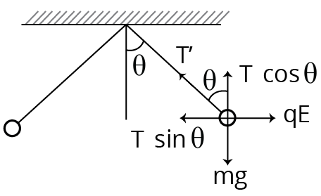
During air
$\mathrm{T} \cos \theta=\mathrm{mg} \ldots . . \text { (i) }$
$\mathrm{T} \sin \theta=\mathrm{qE} \ldots .$ (ii)
$\mathrm{qE}=\mathrm{mg} \tan \theta \ldots . .(\text { iii) }$
In liquid,
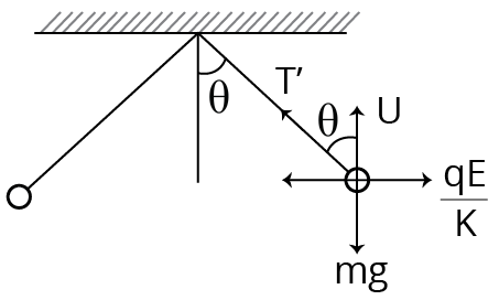
During Liquid
$\mathrm{T}^{\prime} \cos \theta=\mathrm{mg}-\mathrm{U}$$\mathrm{T}^{\prime} \cos \theta=\mathrm{mg}-\rho \mathrm{vg} \ldots . . \text { (iv) }$
$\mathrm{T}^{\prime} \sin \theta=\dfrac{q E}{K} \ldots \ldots(\mathrm{v})$
Dividing Eq. (v) by Eq. (ii), we get
$\dfrac{T^{\prime}}{T}=\dfrac{1}{K} \Rightarrow T^{\prime}=\dfrac{T}{K}=\dfrac{T}{21} \ldots \ldots$
Dividing Eq. (iv) by Eq. (v), we get
$\dfrac{q E}{K}=(\mathrm{mg}-\rho \mathrm{vg}) \tan \theta$
$q E=\mathrm{K}(\mathrm{mg}-\rho \mathrm{vg}) \tan \theta \ldots . . \text { (vii) }$
From Eqs. (vii) and (iii), we get
$\mathrm{mg} \tan \theta=\mathrm{K}(\mathrm{mg}-\rho \mathrm{vg}) \tan \theta$
$\Rightarrow \mathrm{m}=\mathrm{K}(\mathrm{m}-\rho \mathrm{v})$
$\Rightarrow d v=K(d v-\rho v)$
$\Rightarrow \mathrm{d}=\mathrm{Kd}-\mathrm{K} \rho$$\Rightarrow d=21 d-21 \rho[\because K=21]$
$\Rightarrow 20 \mathrm{~d}=21 \rho$$\Rightarrow 20 \mathrm{~d}=21 \times 800$
$\Rightarrow d=840 \mathrm{~kg} / \mathrm{m}^{3}$
Example 2:
A capacitor is connected to a $20 \mathrm{~V}$ battery through a resistance of $10 \Omega$. It is found that the potential difference across the capacitor rises to $2 \mathrm{~V}$ in $1 \mu$ s. The capacitance of the capacitor is ___________$\mu \mathrm{F}$. Given : $\ln \left(\dfrac{10}{9}\right)=0.105$
(A) 9.52
(B) 0.95
(c) 0.105
(D) 1.85
Answer: B
Hint: A capacitor is a device used in electrical circuits to store charges. A capacitor operates on the idea that when an earthed conductor is moved close to a conductor, its capacitance increases noticeably. As a result, a capacitor has two plates with equal and opposite charges separated by a distance.
Complete solution: Given, the peak voltage of the battery, $V_{0}=20 \mathrm{~V}$
The voltage of the battery, $V=2 \mathrm{~V}$
Time, $\mathrm{t}=1 \mu \mathrm{s}=1 \times 10^{-6} \mathrm{~s}$
Resistance of the capacitor, $R=10 \Omega$
As we know that,
$V=V_{0}\left(1-e^{-t / R C}\right)$
Substituting the values in the above equation, we get
$2=20\left(1-\mathrm{e}^{-\mathrm{t} / \mathrm{RC}}\right)$
$\Rightarrow \dfrac{t}{R C}=\ln \left(\dfrac{10}{9}\right)$
$\Rightarrow C=\dfrac{t}{R \ln (10 / 9)}=\dfrac{10^{-6}}{10 \times \ln (10 / 9)}=0.95 \mu \mathrm{F}$
∵ The capacitance of the capacitor is $0.95 \mu \mathrm{F}$.
Common Errors or Mistakes That Should Be Avoided By the Students Keeping the Exam Point of View:
Students forget to write the working formula.
Students also write improper units without checking their compatibility.
Calculation errors when doing problems
Students forget to put in the correct data they used in the working formula, which is used by teachers to check how much effective the students learning.
Incorrect resistor additions
Importance of Class 12 Physics NEET Current Electricity
This chapter is all about current electricity and the scientific terms related to it. It will introduce students to what an electric current is and how it flows within a conductor. It will also teach students how an electric potential drives an electric current from one point to the other.
This chapter will explain all the scientific terms related to electric current, carriers, drift velocity, Ohm’s Law, resistance, factors affecting electric flow, etc. using scientific derivations. Students will learn their meanings and how to define those using mathematical tools.
They will also learn new advanced concepts regarding conductance, resistance, capacitors, semiconductors, etc. They will also learn what cells are and how many types of cells we use. On proceeding further, they will find out what happens when an electric conductor is heated.
These fundamental concepts will be explained in an easier version in the Current Electricity notes. Students will learn these principles and prepare a strong foundation to answer conceptual questions related to this chapter.
Benefits of Vedantu’s Current Electricity Class 12 Notes for NEET
The experts have compiled these notes to deliver an easier medium to prepare current electricity, an important chapter in the Physics NEET syllabus. You will comprehend these new concepts in a better way from the easy description given by the experts.
The concise and organised format of these notes will help you remember all the definitions, descriptions, laws, explanations, and formulae without any difficulty. In fact, you can clarify doubts about this chapter on your own and reduce the preparation time considerably.
Learn how the experts have explained all the concepts in this chapter in a simpler manner and use it to develop your answering skills. Correlate the terms and find out the easiest ways to answer fundamental questions asked in the NEET Exam. Become better at solving such problems based on these principles, terms, and laws.
Recall what you have studied before an exam by revising from these notes at your convenience. Download and use Current Electricity NEET notes according to your study schedule and make it more productive.
Download Current Electricity Notes Class 12th PDF
The PDF version of these notes is available for free. Get these notes today and complete your study material for preparing this chapter in the Class 12 NEET syllabus. Get detailed insights from the concise notes and become better at solving questions. Find out how the experts have answered fundamental sample questions and develop your answering skills considerably.
Other Important Links
Other Important Links for NEET Current Electricity |
NEET Physics Revision Notes - Chapter Pages
NEET Physics Chapter-wise Revision Notes | |
Current Electricity Notes | |
FAQs on NEET 2026 Revision Notes for Physics Current Electricity
1. What do you mean by electrical conductance?
As per the Current Electricity NEET notes PDF, electrical conductance is the measure of electric current flowing through a conductor. It is also the reciprocal of the measurement of electrical resistance.
2. What is electrical resistance?
In simpler terms, the resistance caused by the features of a material to conduct electricity is called electrical resistance. Insulators have higher electrical resistance than conductors.
3. What drives an electric current to flow through a conductor?
The potential difference in a conductor attached to a circuit drives an electric current to flow from one point to the other.
4. What do you mean by current electricity?
The flow of electrons from one point to the other in a conductor due to the difference in electric potential between these two points is called current electricity. A current of electrons is produced due to such a difference.


