


Current Electricity Class 12 Extra Questions and Answers Free PDF Download


Very Short Answer Questions: (1 Marks)
1. If the temperature of a good conductor decreases, how does the relaxation time of electrons in the conductor change?
Ans: It is known that,
$\rho =\frac{m}{n{{e}^{2}}\tau }$
Therefore, if the temperature of a good conductor decreases, collision decreases and thus the relaxation time of electrons increases which in turn decreases the resistivity.
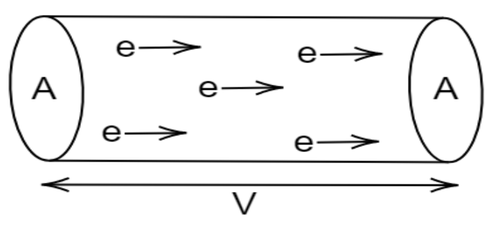
2. If potential difference $V$ applied across a conductor is increased to $2V$, how will the drift velocity of the electron change?
Ans: It is known that,
${{V}_{d}}=\frac{eE\tau }{m}=\frac{eV\tau }{lm}$
When the potential difference across a conductor is doubled, the drift velocity of the electron gets doubled.
3. What is the value of current $I$ at $O$ in the adjoining circuit?
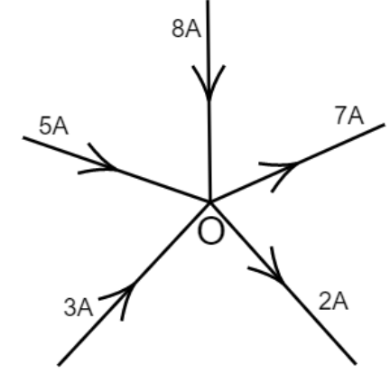
Ans: Total current at O is given by,
$i=5+3-2-7+8$
$\Rightarrow i=16-9$
$\Rightarrow i=7A$
Therefore, the current $I$ at $O$is $i=7A$.
4. State one condition for maximum current to be drawn from the cell?
Ans: It is known that,
$I=\frac{E}{R+r}$
To find maximum current, internal resistance must be zero.
5. Resistivities of copper, silver and manganin are $1.7\times {{10}^{-8}}m$, $1.0\times {{10}^{-8}}m$ and $44\times {{10}^{-8}}m$ respectively which of these is the best conductor?
Ans: The resistance is directly proportional to specific resistance (resistivity), when length and area of cross-section is made constant.$R=\frac{\rho l}{A}$
Hence, silver is the best conductor as its specific resistance is less.
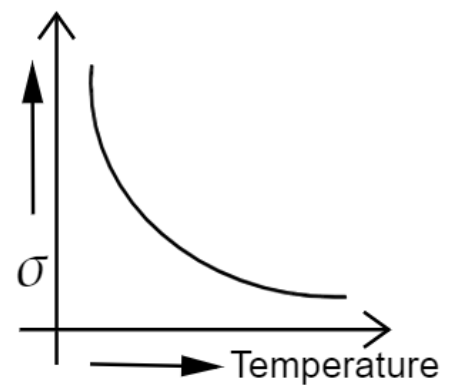
6. Draw the graph showing the variation of conductivity with temperature for a metallic conductor?
Ans: The conductivity for a metallic conductor decreases with the increase in temperature.
7. If a wire is stretched to double its length, what will be its new resistivity?
Ans: There will be no change in resistivity because resistivity depends only on the nature of the material.
8. Name any one material having a small value of temperature coefficient of resistance. Write one use of this material?
Ans: Material having a small value of temperature coefficient of resistance is Nichrome. It is an alloy used for making standard resistance coil.
9. Two wires $A$ and $B$ are of the same metal and of same length have their areas of cross section in the ratio $2:1$ if the same potential difference is applied across each wire in turn, what will be the ratio of current flowing in $A$ & $B$ ?
Ans: It is known that,
$I=\frac{V}{R}$ and $R<\frac{1}{A}$
When area of cross section is $2:1$ then the ratio of current flowing in $A$ & $B$ will be $1:2$.
Very Short Answer Questions: (2 Marks)
1. Two electric bulbs A and B are marked \[\mathbf{220V}\],$40W$ and $220V$$60W$ respectively. Which one has a higher resistance?
Ans: It is known that,
$R=\frac{{{V}^{2}}}{p}$
For Bulb $A$, ${{R}_{1}}=\frac{{{(220)}^{2}}}{40}=1210\Omega $
For Bulb $B$, ${{R}_{2}}=\frac{{{(220)}^{2}}}{60}=806.67\Omega $
Therefore, bulb $A$ has higher resistance.
2. A Carbon resistor has three strips of red colour and a gold strip. What is the value of the resistor? What is its tolerance?
Ans: It is given that,
\[R\text{ }R\text{ }R\text{ }Gold=(22\times {{10}^{2}})\pm 5%\]
Therefore, value of the resistor$=2200\Omega $ and tolerance$=\pm 5%$
3. Determine the voltage drop across the resistor ${{R}_{1}}$ in the circuit given below with \[\mathbf{E}=\text{ }\mathbf{60V}\], ${{R}_{1}}=18\Omega $, ${{R}_{2}}=10\Omega $, ${{R}_{3}}=5\Omega $ and ${{R}_{4}}=10\Omega $.
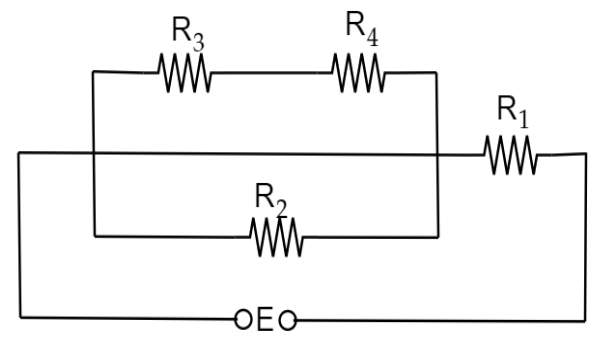
Ans: In the given circuit,
${{R}_{3}}\And {{R}_{4}}$ are in series
$R'={{R}_{3}}+{{R}_{4}}$
\[\Rightarrow R'=5+10=15\Omega \]
Then, $R'\And {{R}_{2}}$ are in parallel
$\frac{1}{R''}=\frac{1}{{{R}^{1}}}+\frac{1}{{{R}_{2}}}$
$\Rightarrow \frac{1}{R''}=\frac{1}{15}+\frac{1}{10}$
$\Rightarrow \frac{1}{R''}=\frac{4+6}{60}=\frac{10}{60}$
$\Rightarrow R''=\frac{60}{10}=6\Omega $
Then ${{R}_{1}},R''$ are series
${{R}_{net}}=R''+{{R}_{1}}$
$\Rightarrow {{R}_{net}}=6+18=24\Omega $
Current: $I=\frac{V}{R}=\frac{60}{24}\text{ampere}$
Voltage drop across ${{R}_{1}}=I{{R}_{1}}=\frac{60}{24}\times 18$
$\Rightarrow {{V}_{1}}=45v\text{olts}$
Therefore, voltage drop across the resistor ${{R}_{1}}$ is $45volts$.
4. Two heated wires of the same dimensions are first connected in series and then it’s parallel to a source of supply. What will be the ratio of heat produced in the two cases?
Ans: It is known that,
$\text{ }H={{I}^{2}}\operatorname{R}t$ $\left( I=\frac{V}{R} \right)$
$\Rightarrow H=\frac{{{V}^{2}}}{{{R}^{2}}}\times R\times t$
$\Rightarrow H=\frac{{{V}^{2}}}{R}t$
$\Rightarrow H\propto \frac{1}{R}$
\[\frac{\text{ }{{\text{H}}_{\text{series}}}\text{ }}{\text{ }{{\text{H}}_{\text{parallel}}}\text{ }}=\frac{\text{ }{{\text{R}}_{\text{parallel}}}\text{ }}{\text{ }{{\text{R}}_{\text{series}}}\text{ }}\]
\[\Rightarrow \frac{\frac{1}{\left( \frac{1}{R}+\frac{1}{R} \right)}}{R+R}=\frac{R/2}{2R}=\frac{R}{2R\times 2}=\frac{1}{4}\]
Therefore, the ratio of heat produced is$1:4$.
5. V.i graph for a metallic wire at two different temperatures is shown in the figure. Which of these two temperatures is higher and why?
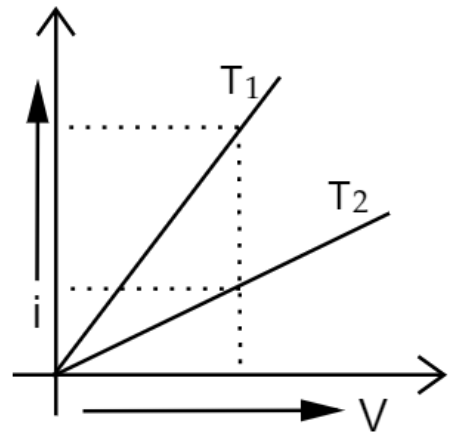
Ans: From the graph:
$Slope=\frac{i}{V}$
It is known that, $\frac{i}{V}=\frac{1}{R}$
It means that the smaller the slope, the larger the resistance.
As the resistance increases, temperature also increases.
Temperature of ${{T}_{2}}$ is higher because ${{T}_{2}}$ has a small slope.
6. A set of n-identical resistors, each of resistance $R$ ohm when connected in series have an effective resistance of $X$ ohm and when the resistors are connected in parallel the effective resistance is $Y$ ohm. Find the relation between $R$,$X$ and $Y$?
Ans: It is given that,
n-resistors connected in series
$\Rightarrow X=nR$ ……$(1)$
n-resistors connected in parallel
$\Rightarrow Y=\frac{R}{n}$ ……$(2)$
Multiply equations $(1)$ and $(2)$
$\Rightarrow XY=nR\times \frac{R}{n}$
$\Rightarrow XY={{R}^{2}}$
$\Rightarrow R=\sqrt{XY}$
7. Show that the resistance of a conductor is given by $R=\frac{ml}{n{{e}^{2}}\tau A}$.
Ans: Consider a conductor of length $l$ and area $A$.
If electric field $E$ is applied across the conductor,
The drift velocity of electrons ${{v}_{d}}$ is given by:
${{v}_{d}}=\frac{eE}{m}\tau $
It is known that, $I=neA{{v}_{d}}$
$\Rightarrow \text{I}=\operatorname{neA}\left( \frac{eE}{m}\tau \right)$; $E=\frac{V}{l}$
$\Rightarrow \text{I}=\operatorname{neA}\left( \frac{eV}{ml}\tau \right)$
$\Rightarrow \frac{V}{I}=\frac{ml}{n{{e}^{2}}A\tau }$;$\frac{V}{I}=R$
$\Rightarrow R=\frac{m}{n{{e}^{2}}\tau }\left( \frac{l}{A} \right)$
$\Rightarrow \text{R}=\frac{ml}{n{{e}^{2}}\tau A}$
Therefore, the resistance of the conductor, $\text{R}=\frac{ml}{n{{e}^{2}}\tau A}$
8. Figure shows a piece of pure semiconductor $S$ in series with a variable resistor $R$ and a source of constant voltage $V$. Would you increase and decrease the value of $R$ to keep the reading of ammeter $(A)$ constant, when semiconductor $S$ is heated? Give reasons.
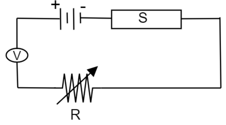
Ans: On increasing the temperature, resistance of the semiconductor decreases. So, to increase the temperature, the semiconductor $S$ is heated.
To maintain constant current in ammeter, total resistance of the circuit should remain unchanged.
Therefore, the value of $R$ has to be increased.
9. Why is constantan or manganin used for making standard resistors?
Ans: Constantan or manganin are alloys of high resistivity and low temperature coefficient of resistance. So, these are used for making standard resistors.
10. What are ohmic and non-ohmic resistors? Give one example of each?
Ans: Ohmic resistors are resistors which obey ohm’s law. Eg: Metals
Non-ohmic resistors are resistors which do not obey ohm’s law. Eg: semiconductor diode, transistor etc.
11. The storage battery of a car has an emf of $12V$. If the internal resistance of the battery is $0.4\Omega $, what is the maximum current that can be drawn from the battery?
Ans: It is given that,
Emf of the battery, \[E=\text{ }12\text{ }V~\]
Internal resistance of the battery\[,r=\text{ }0.4\text{ }\Omega ~\]
It is known that,
$V=E-iR$
To get maximum current from that battery:
$\Rightarrow E-iR=0$
$\Rightarrow E=iR$
$\Rightarrow i=\frac{E}{R}=\frac{12}{0.4}$
$\Rightarrow i=30A$
Therefore, the maximum current drawn from the given battery,$i=30A$.
12. In a potentiometer arrangement, a cell of emf $1.25V$ gives a balance point at $35.0cm$ length of the wire. If the cell is replaced by another cell and the balance point shifts to $63.0cm$, what is the emf of the second cell?
Ans: It is given that,
Emf of the cell, ${{E}_{1}}=1.25V$
Balance point of the potentiometer, ${{l}_{1}}=35cm$
The cell is replaced by another cell of emf ${{E}_{2}}$
New balance point of the potentiometer, ${{l}_{2}}=63cm$
Balance condition of potentiometer: $\frac{{{E}_{1}}}{{{E}_{2}}}=\frac{{{l}_{1}}}{{{l}_{2}}}$
$\Rightarrow {{E}_{2}}={{E}_{1}}\times \frac{{{l}_{2}}}{{{l}_{1}}}$
$\Rightarrow {{E}_{2}}=1.25\times \frac{63}{35}=2.25~\text{V}$
Hence, the emf of the second cell $2.25V$.
13. What conclusion can you draw from the following observations on a resistor made of alloy manganin?
Ans: It can be concluded that the ratio of voltage with current is constant and is equal to $19.7$ i.e., it obeys Ohm’s law. Therefore, manganin is an ohmic conductor.
From Ohm’s law, $\frac{V}{I}=R$ i.e., the ratio of voltage with current is the resistance of the conductor. Thus, the resistance of manganin is $19.7\Omega $.
Short Answer Questions: (3 Marks)
1. What happens to the resistance of the wire when its length is increased to twice its original length?
Ans: It is known that,
$R=\rho \frac{l}{A}=\rho (\frac{l}{\pi {{r}^{2}}})$
It is given that,
New length of the wire, $l'=2l$
Let, the new radius be $r'$.
As volume of the wire remains the same: $\pi {{\text{r}}^{2}}\ell =\pi {{(r')}^{2}}\ell '$
$\Rightarrow \pi {{r}^{2}}l=\pi {{(r')}^{2}}2\ell $
\[\Rightarrow {{(r')}^{2}}=\frac{{{r}^{2}}}{2}\]
New resistance, $R'=\rho \left( \frac{l'}{\pi r{{'}^{2}}} \right)$
$\Rightarrow R'=\rho \frac{2l}{\pi \left( \frac{{{r}^{2}}}{2} \right)}$
$\Rightarrow R'=\rho \left( \frac{4l}{\pi {{r}^{2}}} \right)$
$\Rightarrow R'=4\rho \left( \frac{l}{\pi {{r}^{2}}} \right)$
$\Rightarrow R'=4R$
Hence, new resistance becomes four times the original resistance.
2. Mark the direction of current in the circuit as per Kirchhoff’s first rule. What is the value of the main current in the shown network?
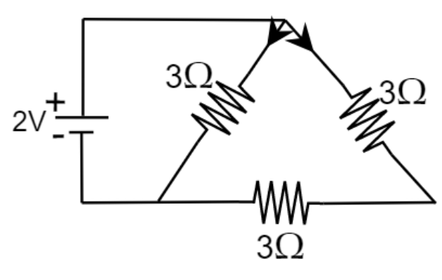
Ans: In the given figure,
${{R}_{2}}$ and ${{R}_{3}}$ are in series
$\Rightarrow R=3+3=6\Omega $
$R$ and ${{R}_{1}}$ are in parallel
$\frac{1}{{{R}_{net}}}=\frac{1}{R}+\frac{1}{{{R}_{1}}}$
$\Rightarrow \frac{1}{{{R}_{net}}}=\frac{1}{6}+\frac{1}{3}=\frac{3+6}{18}$
$\Rightarrow {{R}_{net}}=\frac{18}{9}=2\Omega $
Net current: $I=\frac{V}{R}$
$I=\frac{2}{2}=1A$
Therefore, net current is $1A$.
3.
(a) Why do we prefer a potentiometer to measure the emf of a cell rather than a voltmeter?
Ans: Potentiometer is based on a null method i.e.; it draws no current from the cell. Emf of a cell is equal to the terminal potential difference when no current flows from the cell. Therefore, a potentiometer is preferred to measure the emf of a cell rather than a voltmeter.
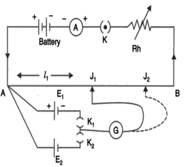
(b) With suitable circuit diagram, show how emfs of 2 cells can be compared using a potentiometer?
Ans: Potentiometer works on the principle that when a constant current flows through the wire of uniform area of cross-section then
Condition:
Close the switch 1 and 3 such that ${{E}_{1}}$comes in the circuit.
Potential Difference across AJ is ${{V}_{AJ}}<{{I}_{1}}$
It is known that, no current flows between ${{E}_{1}}$ and ${{V}_{AJ}}$
$\Rightarrow {{V}_{AJ}}={{E}_{1}}$
${{E}_{1}}<{{l}_{1}}$
$\Rightarrow {{E}_{1}}=k{{l}_{1}}$ ……$(1)$
Condition:
Close the switch 2 and 3 such that ${{E}_{2}}$ comes in the circuit and balance point is obtained of ${{J}_{1}}$ .
Since no current flows between $A{{J}_{1}}$ and ${{E}_{2}}$
$\Rightarrow {{V}_{A{{J}_{1}}}}={{E}_{2}}$
${{E}_{2}}<{{l}_{2}}$
$\Rightarrow {{E}_{2}}=k{{l}_{2}}$ ……$(2)$
$\Rightarrow {{V}_{AJ}}={{E}_{2}}=k{{l}_{2}}$
Dividing equations $(1)$ and $(2)$
$\Rightarrow \frac{{{E}_{1}}}{{{E}_{2}}}=\frac{k{{l}_{1}}}{k{{l}_{2}}}$
$\Rightarrow \frac{{{E}_{1}}}{{{E}_{2}}}=\frac{{{l}_{1}}}{{{l}_{2}}}$
Therefore, $\frac{{{E}_{1}}}{{{E}_{2}}}=\frac{{{l}_{1}}}{{{l}_{2}}}$.
4. Potential difference $V$ is applied across the ends of copper wire of length $l$ and diameter $D$. What is the effect on drift velocity of electrons if
(a) \[V\] is doubled
Ans: It is known that,
${{V}_{d}}=\frac{I}{neA}=\frac{V}{R(neA)}$
$\Rightarrow {{V}_{d}}=\frac{V}{\left( \rho \frac{\ell }{A} \right)(neA)}=\frac{V}{ne\rho \ell }$
Therefore, when $V$ is doubled, drift velocity gets doubled.
(b) $\ell $ is doubled
Ans: It is known that,
${{V}_{d}}=\frac{I}{neA}=\frac{V}{R(neA)}$
$\Rightarrow {{V}_{d}}=\frac{V}{\left( \rho \frac{\ell }{A} \right)(neA)}=\frac{V}{ne\rho \ell }$
Therefore, when $l$ is doubled, drift velocity gets halved.
(c) D is doubled
Ans: It is known that,
${{V}_{d}}=\frac{I}{neA}=\frac{V}{R(neA)}$
$\Rightarrow {{V}_{d}}=\frac{V}{\left( \rho \frac{\ell }{A} \right)(neA)}=\frac{V}{ne\rho \ell }$
Therefore, as $V$ is independent of $D$, drift velocity remains unchanged.
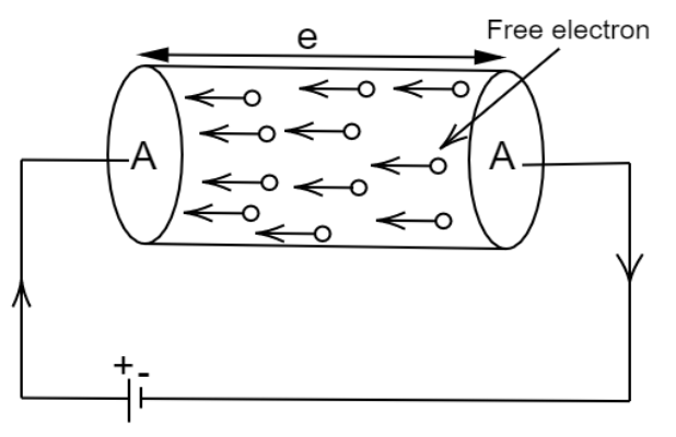
5. What is drift velocity? Derive expression for drift velocity of electrons in a good conductor in terms of relaxation time of electrons?
Ans: Drift velocity is defined as the average velocity with which free electrons get drifted in a direction opposite to that of an electric field.
Let, $m$ be the mass of the electron and $e$ be the charge of electrons.
When electric field $E$ is applied, acceleration acquired by the electron is $a=\frac{eE}{m}$.
From, first equation of motion: $v=u+at$
Average initial velocity, $u=OV={{v}_{d}}$
Relaxation time, $t=\tau $
$\Rightarrow {{v}_{d}}=a\tau $
$\Rightarrow {{v}_{d}}=\frac{eE\tau }{m}$
Where,
$e$ is the change on electron
$E$ is the electric field intensity
$\tau $ is the relaxation time
$m$ is the mass of electron
Therefore, the expression for drift velocity of electrons in a good conductor in terms of relaxation time of electrons is ${{v}_{d}}=\frac{eE\tau }{m}$.
6. The potentiometer circuit shown, the balance (null) point is at $X$. State with reason, where the balance point will be shifted when
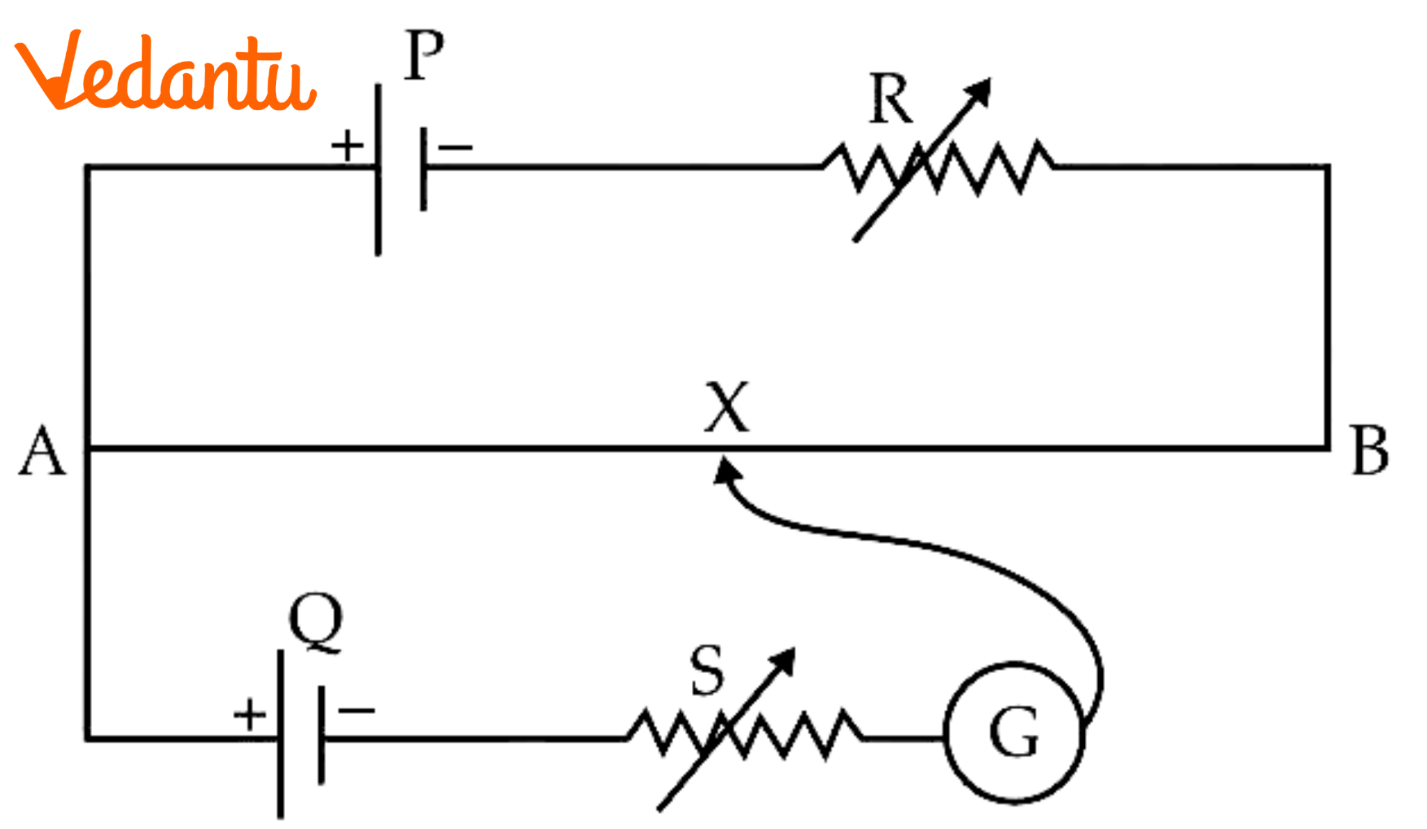
(a) Resistance R is increased, keeping all parameters unchanged.
Ans: If resistance $R$ is increased, then the current through potentiometer wire $AB$ will decrease. Therefore, the potential difference across $A$ will decrease and balance point shifts towards $B$.
(b) Resistance S is increased, keeping R constant.
Ans: If resistance $S$ is increased, then the terminal potential difference of the battery will decrease. Therefore, the balance point will be obtained at a smaller length and thus shifts towards $A$.
(c) Cell P is replaced by another cell whose emf is lower than that of cell Q.
Ans: If cell $P$ is replaced by another cell whose emf is lower than that of cell Q, then the potential difference across $AB$ will be less than that of emf Q. Therefore, the balance point will not be obtained.
7.
(a) Using the principle of Wheatstone bridge describes the method to determine the specific resistance of a wire in the laboratory. Draw the circuit diagram and write the formula used?
Ans: Firstly, close the Key $(k)$ and move the jockey along the wire till a certain point $B$ is reached where the galvanometer shows no deflection. Therefore, the bridge is said to be balanced.
If $Rcm$is the resistance per cm length of the wire then.
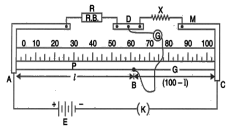
$\frac{R}{X}=\frac{lRcm}{(100-l)Rcm}$
$X=\frac{R(100-l)}{l}$
It is known that,
$P=\frac{XA}{l'}$, $l'$is the length if the wire
$P=\frac{R(100-l)A}{l(l')}$
Therefore, the point is located at, $P=\frac{R(100-l)A}{l(l')}$.
(b) In a Wheatstone bridge experiment, a student by mistake connects key $(k)$ in place of galvanometer and galvanometer $(G)$ in place of Key $(K)$. What will be the change in the deflection of the bridge?
Ans: If the bridge is balanced, then there will be no current in the key. Therefore, constant current flows through the galvanometer and thus there will be no change in deflection of the bridge.
8. Two primary cells of emf ${{E}_{1}}$ and ${{E}_{2}}$ are connected to the potentiometer wire $AB$ as shown in the figure if the balancing length for the two combinations of the cells are $250cm$ and $400cm$. Find the ratio of ${{E}_{1}}$ and ${{E}_{2}}$ .
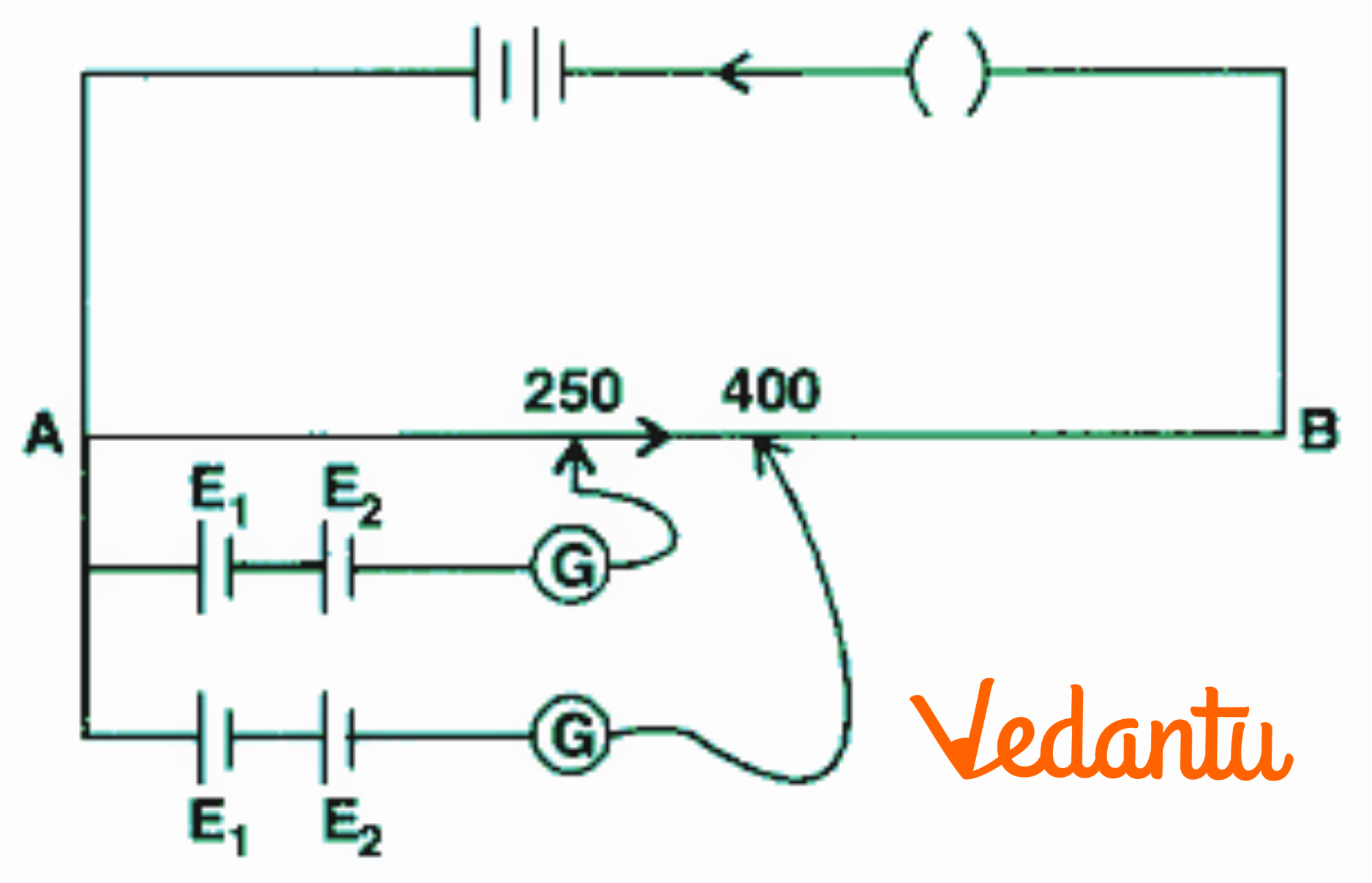
Ans: It is known that,$E=kl$
$\text{ }{{E}_{1}}-{{E}_{2}}=K\times 250$ ……$(1)$
${{E}_{1}}+{{E}_{2}}=K\times 400$ ……$(2)$
Adding equations $(1)$ and $(2)$
$2{{E}_{1}}=250~K+400K$
\[2{{E}_{1}}=250~K+400\]
$2{{E}_{1}}=650K$
${{E}_{1}}=\frac{650}{2}K$
${{E}_{1}}=325K$
Substituting ${{E}_{1}}=325K$ in equation$(1)$
$\text{ 325K}-{{E}_{2}}=K\times 250$
${{E}_{2}}=325K-250K$
${{E}_{2}}=75K$
Divide ${{E}_{1}}$ and ${{E}_{2}}$
\[\Rightarrow \frac{{{E}_{1}}}{{{E}_{2}}}=\frac{325K}{75K}\]
\[\Rightarrow \frac{{{E}_{1}}}{{{E}_{2}}}=4.33\]
The ratio of ${{E}_{1}}$ and ${{E}_{2}}$ is $4.33$.
9. Explain with the help of a circuit diagram, how the value of an unknown resistance can be determined using a Wheatstone bridge?
Ans: In this case \[P,\text{ }Q,\text{ }R\] are known resistance and $X$ is an unknown resistance.
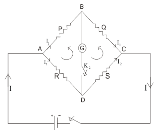
Applying Kirchhoff’s law for closed path \[ABDA\].
${{I}_{1}}P+{{I}_{3}}G-{{I}_{2}}R=0$ ……$(1)$
For closed path \[~BCDB\]
$({{I}_{1}}-{{I}_{3}})Q-({{I}_{2}}+{{I}_{3}})X-{{I}_{3}}G=0$ …… $(2)$
The bridge is said to be balanced when no current flows through the galvanometer.
$\Rightarrow Ig=0$ $({{I}_{g}}={{I}_{3}})$
Equation $(1)\Rightarrow {{I}_{1}}P={{I}_{2}}R$
\[\Rightarrow \frac{{{I}_{1}}}{{{I}_{2}}}=\frac{R}{P}\] ……$(3)$
Equation $(2)\Rightarrow {{I}_{1}}Q={{I}_{2}}X$
\[\Rightarrow \frac{{{I}_{1}}}{{{I}_{2}}}=\frac{X}{Q}\] ……$(4)$
Equating equations $(3)$and $(4)$
$\frac{R}{P}=\frac{X}{Q}\Rightarrow X=\frac{RQ}{P}$
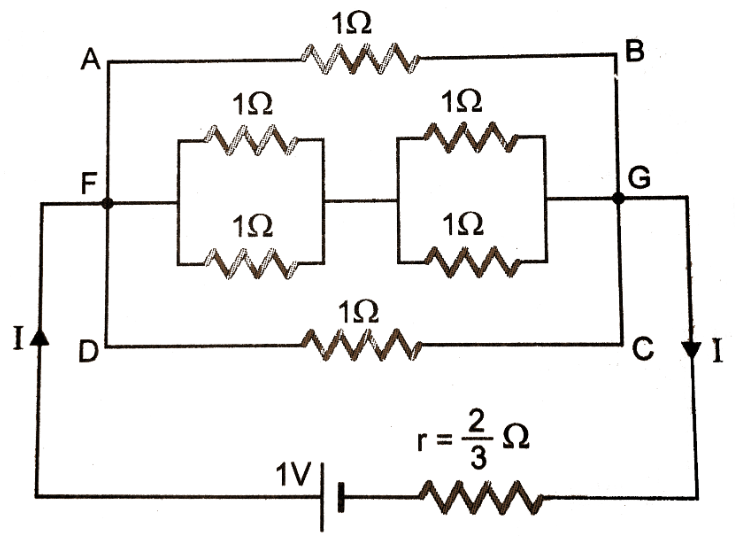
10. Find the current drawn from a cell of emf $1V$ and internal resistance \[\frac{2}{3}\Omega \] connected to the network shown in the figure. $E=1V$ , $r=\frac{2}{3}\Omega $.
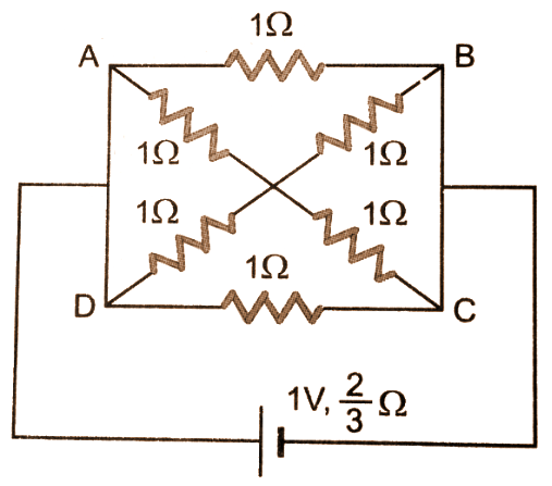
Ans: The circuit can be redrawn as follows:
$\Rightarrow \text{ }\frac{I}{{{R}_{1}}}=\frac{1}{1}+\frac{1}{1}$
$\Rightarrow \frac{1}{{{R}_{1}}}=2$
$\Rightarrow {{R}_{1}}=\frac{1}{2}$
Similarly,
$\Rightarrow {{R}_{2}}=\frac{1}{2}$
$R={{R}_{1}}+{{R}_{2}}$
$\Rightarrow R=\frac{1}{2}+\frac{1}{2}$
$\Rightarrow R=1\Omega $
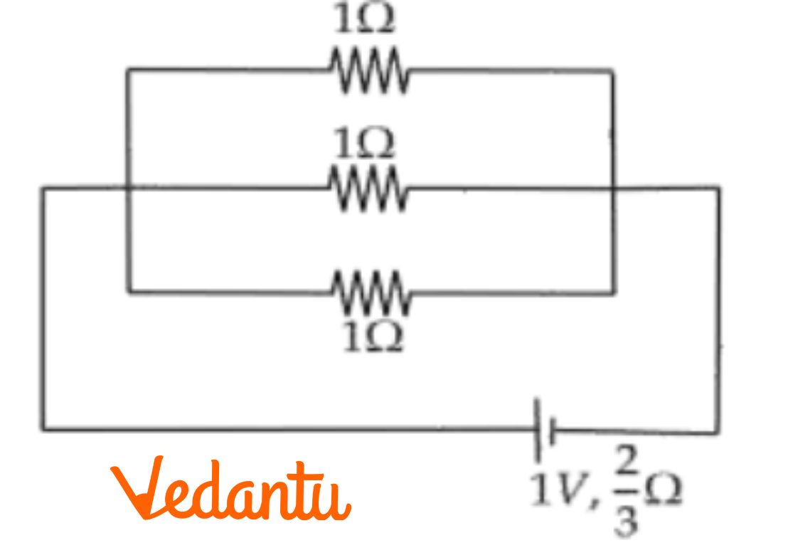
Here, \[1\Omega ,1\Omega \] and \[1\Omega \] are in parallel.
$\Rightarrow \frac{1}{{{R}_{net}}}=\frac{1}{1}+\frac{1}{1}+\frac{1}{1}$
$\Rightarrow \frac{1}{Rnet}=\frac{3}{1}$
$\Rightarrow \text{ Rnet }=\frac{3}{1}\Omega ~$
$\text{I}=\frac{E}{R+r}=\frac{1}{\frac{3}{1}+\frac{3}{3}}=\frac{3}{3}=1A$
$\Rightarrow I=1A$
Current drawn from a cell of emf $1V$ is $I=1A$.
11.
(a) State and explain Kirchhoff’s law?
Ans: Kirchhoff’s first law: It states that the algebraic sum of currents at a junction in an electrical circuit is always zero.
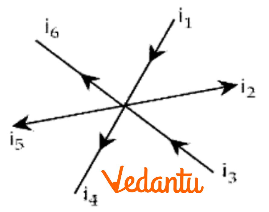
$\Rightarrow {{i}_{1}}-{{i}_{2}}+{{i}_{3}}-{{i}_{4}}-{{i}_{5}}-{{i}_{6}}=0$
Kirchhoff’s second law: It states that in any closed part of an electrical circuit, the algebraic sum of emf is equal to the algebraic sum of the products of resistances and current flowing through them. Eg: For closed path \[ABCA~\]
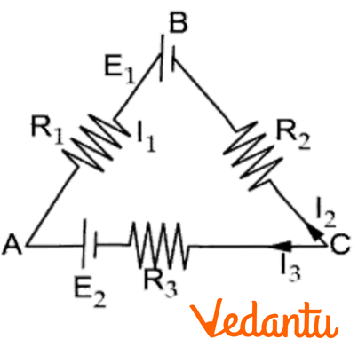
${{R}_{1}}{{I}_{1}}-{{R}_{3}}{{I}_{3}}+{{R}_{2}}{{I}_{2}}-{{E}_{1}}+{{E}_{2}}=0$
${{E}_{1}}-{{E}_{2}}={{R}_{1}}{{I}_{1}}-{{R}_{3}}{{I}_{3}}+{{R}_{2}}{{I}_{2}}$
(b) In the network shown, find the values of current ${{I}_{1}},{{I}_{2}},{{I}_{3}}$.
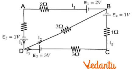
Ans: Applying Kirchhoff’s law at point D
${{I}_{1}}={{I}_{2}}+{{I}_{3}}$ ……$(1)$
For closed path \[ABDA\]
$2{{I}_{1}}+1-2+{{I}_{1}}+3{{I}_{2}}=0$
$3{{I}_{1}}+3{{I}_{2}}-1=0$
$3{{I}_{1}}+3{{I}_{2}}=1$ ……$(2)$
For closed path \[DBCD\]
$3{{I}_{2}}-1-{{I}_{3}}-3{{I}_{3}}+3=0$
$3{{I}_{2}}-4{{I}_{3}}+2=0$
$4{{I}_{3}}-3{{I}_{2}}-2=0$
$4{{I}_{3}}-3{{I}_{2}}=2$ ……$(3)$
Substituting $(1)$ in $(2)$
$(2)\Rightarrow 3({{I}_{2}}+{{I}_{3}})+3{{I}_{2}}=1$
$(2)\Rightarrow 6{{I}_{2}}+3{{I}_{3}}=1$
$(3)\Rightarrow 4{{I}_{3}}-3{{I}_{2}}=2$
$2\times (3)\Rightarrow 8{{I}_{3}}-6{{I}_{2}}=4$ ……$(4)$
$(3)+(4)=11{{I}_{3}}=5$
$\Rightarrow {{I}_{3}}=\frac{5}{11}A$
Substituting ${{I}_{3}}$ in equation $(3)$
$\Rightarrow 4(\frac{5}{11})-3{{I}_{2}}=2$
$\Rightarrow \frac{20}{11}-3{{I}_{2}}=2$
$\Rightarrow \frac{20}{11}-2=3{{I}_{2}}$
$\Rightarrow \frac{-2}{11}=3{{I}_{2}}$
$\Rightarrow {{I}_{2}}=\frac{-2}{33}A$
Substituting ${{I}_{2}}$,${{I}_{3}}$ in equation $(1)$
${{I}_{1}}=\frac{-2}{33}+\frac{5}{11}$
$\Rightarrow {{I}_{1}}=\frac{13}{33}A$
Currents are ${{I}_{1}}=\frac{13}{33}A$, ${{I}_{2}}=\frac{-2}{33}A$ and ${{I}_{3}}=\frac{5}{11}A$.
12. The variation of resistance of a metallic conductor with temperature is given in figure.
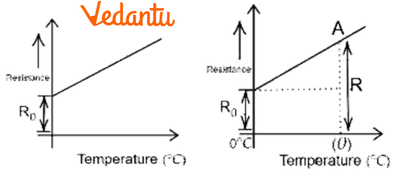
(a) Calculate the temperature coefficient of resistance from the graph.
Ans: It is known that,
Temperature coefficient of Resistance:$\alpha =\frac{R-{{R}_{0}}}{{{R}_{0}}\theta }$
where $R$ is the resistance of the conductor and $\theta $ is the temperature corresponding to point A.
(b) State why the resistance of the conductor increases with the rise in temperature.
Ans: It is known that,
$R=\rho \frac{l}{A}=\frac{m}{n{{e}^{2}}\tau }(\frac{t}{A})$
where $\rho $is the resistivity.
When temperature increases, the number of collisions increases, average relaxation time decreases, therefore resistance increases.
13. A circle ring having negligible resistance is used to connect four resistors of resistances \[\mathbf{6R},\mathbf{6R},\mathbf{6R}\] and $R$ as shown in the figure. Find the equivalent resistance between points A & B.
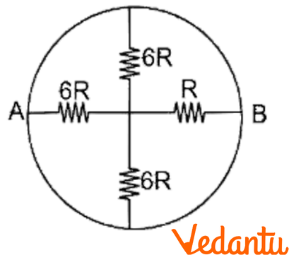
Ans: The given circuit can be redrawn as follows:
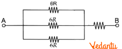
\[6R,6R\] and $6R$ are in parallel.
$\Rightarrow \frac{1}{{{R}_{s}}}=\frac{1}{6R}+\frac{1}{6R}+\frac{1}{6R}$
$\Rightarrow \frac{1}{{{R}_{s}}}=\frac{3}{6R}$
$\Rightarrow {{R}_{S}}=\frac{6R}{3}=2R$
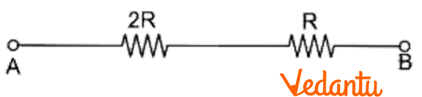
${{R}_{S}}=2R$ and $R$ are in series.
${{R}_{net}}=2R+R$
${{R}_{net}}=3R$
14. A battery of emf $E$ and internal resistance $r$ sends a current, ${{I}_{1}},{{I}_{2}}$ when connected to an external resistance of ${{R}_{1}},{{R}_{2}}$ respectively. Find the emf. and internal resistance of the battery.
Ans: It is given that,
$E$ is the emf of a battery
$r$ is the internal resistance which sends currents ${{I}_{1}},{{I}_{2}}$
${{R}_{1}},{{R}_{2}}$ are external resistances
Current ${{I}_{1}}$ can be written as: ${{I}_{1}}=\frac{E}{{{R}_{1}}+r}$
$E={{I}_{1}}({{R}_{1}}+r)$ ……$(1)$
Similarly, $E={{I}_{2}}({{R}_{2}}+r)$ ……$(2)$
From equations $(1)$ and $(2)$
$\Rightarrow {{I}_{1}}({{R}_{1}}+r)={{I}_{2}}({{R}_{2}}+r)$
$\Rightarrow {{I}_{2}}r-{{I}_{1}}r={{I}_{1}}{{R}_{1}}-{{I}_{2}}{{R}_{2}}$
$\Rightarrow r\left( {{I}_{2}}-{{I}_{1}} \right)={{I}_{1}}{{R}_{1}}-{{I}_{2}}{{R}_{2}}$
${*{35}{l}} \Rightarrow r=\frac{{{I}_{1}}{{R}_{1}}-{{I}_{2}}{{R}_{2}}}{{{I}_{2}}-{{I}_{1}}}$
Emf of the battery,$E$
$\Rightarrow E={{I}_{1}}\left( {{R}_{1}}+r \right)$
$\Rightarrow E={{I}_{1}}\left[ {{R}_{1}}+\frac{{{\text{I}}_{1}}{{\text{R}}_{1}}-{{\text{I}}_{2}}{{\text{R}}_{2}}}{{{\text{I}}_{2}}-{{\text{I}}_{1}}} \right]$
$\Rightarrow E={{I}_{1}}\left[ \frac{{{\text{I}}_{2}}{{\text{R}}_{1}}-{{\text{I}}_{1}}{{R}_{1}}+{{I}_{1}}{{\text{R}}_{1}}-{{\text{I}}_{2}}{{\text{R}}_{2}}}{{{\text{I}}_{2}}-{{\text{I}}_{1}}} \right]$
$\Rightarrow E=\frac{{{I}_{1}}{{I}_{2}}\left( {{\text{R}}_{1}}-{{\text{R}}_{2}} \right)}{{{\text{I}}_{2}}-{{\text{I}}_{1}}}$
Therefore, emf and internal resistance of the battery are $E=\frac{{{I}_{1}}{{I}_{2}}\left( {{\text{R}}_{1}}-{{\text{R}}_{2}} \right)}{{{\text{I}}_{2}}-{{\text{I}}_{1}}}$
and
${*{35}{l}} r=\frac{{{I}_{1}}{{R}_{1}}-{{I}_{2}}{{R}_{2}}}{{{I}_{2}}-{{I}_{1}}}$
15. Find the value of unknown resistance $X$ in the circuit shown in the figure if no current flows through the section AO. Also calculate the current drawn by the circuit from the battery of emf. $6V$ and negligible internal resistance.
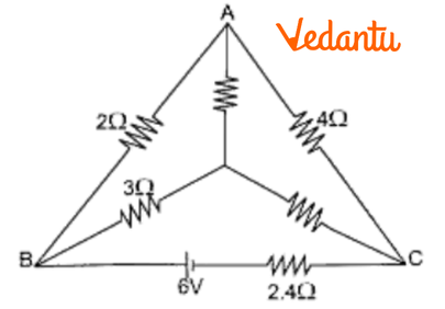
Ans: It is given that no current flows through AO then the circuit is said to be a balanced Wheatstone bridge.
$\Rightarrow \frac{2}{4}=\frac{3}{X}$
$\Rightarrow X=\frac{12}{2}=6$
$\Rightarrow X=6\Omega $
In branch AO, \[I=0\]
Resistance of $10\Omega $ between A and O is ineffective and the circuit is reduced to:
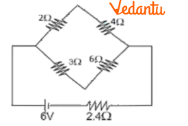
\[2\Omega \] and \[4\Omega \] are in series; \[3\Omega \] and \[6\Omega \] are in series

6Ω and 9Ω are in parallel.
$\Rightarrow \frac{1}{{{R}_{P}}}=\frac{1}{6}+\frac{1}{9}=\frac{9+6}{54}=\frac{15}{54}$
$\Rightarrow {{R}_{P}}=\frac{54}{15}\Omega $
${{R}_{P}}$ and \[2.4\Omega \] are in series
$\Rightarrow {{R}_{eff}}=2.4+\frac{54}{15}$
$\Rightarrow {{R}_{eff}}=\frac{24}{10}+\frac{54}{15}=\frac{360+540}{150}=\frac{900}{150}$
$\Rightarrow {{R}_{eff}}=6\Omega $
Current: $I=\frac{V}{R}=\frac{6}{6}=1$
$\Rightarrow I=1A$
Therefore, the unknown resistance $X=6\Omega $ and current drawn by the circuit from the battery is $I=1A$.
16.
(a) Obtain ohm’s law from the expression for electrical conductivity.
Ans: It is known that,
$I=neA{{v}_{d}}$
$J=\frac{I}{A}=ne{{v}_{d}}$
${{V}_{d}}=\frac{eE\tau }{m}$
$\Rightarrow J=\frac{n{{e}^{2}}E\tau }{m}$ ; $J=\sigma E$
$\sigma =\frac{J}{E}=\frac{n{{e}^{2}}\tau }{m}$
Let $l$ and $A$ be the length and area of the wire.
$I=JA$
$\Rightarrow I=\frac{n{{e}^{2}}E\tau }{m}\times A$ ; $(E=\frac{V}{l})$
$\Rightarrow I=\frac{n{{e}^{2}}V\tau }{ml}A$
$\Rightarrow V=\left( \frac{m}{n{{e}^{2}}\tau } \right)\left( \frac{l}{A} \right)I$
$\therefore V=RI$
$\Rightarrow R=\rho \frac{l}{A}$ where, $\rho =\frac{m}{n{{e}^{2}}\tau }$(Specific resistance of a wire)
(b) A cylindrical wire is stretched to increase its length by $10%$ calculate the percentage increase in resistance?
Ans: It is given that; the length of cylindrical wire is stretched to increase its length by $10%$.
Let, the original length be $l$ and the new length be $l'$.
$\Rightarrow l'=l+\frac{10}{100}l$
$\Rightarrow l'=1.1l$
$\Rightarrow \frac{l'}{l}=1.1$
As the volume of the wire remains the same
$Al=A'l'$
$\frac{A'}{A}=\frac{l}{l'}$
It is known that, $\text{R=}\rho \frac{l}{A}$
$R'=\rho \frac{l'}{A'}$
$\Rightarrow \frac{R'}{R}=\frac{l'}{A'}\times \frac{A}{l}$
\[\Rightarrow \frac{R'}{R}=\frac{l'}{l}\times \frac{l'}{l}={{\left( \frac{l'}{l} \right)}^{2}}\]
$\Rightarrow \frac{R'}{R}={{(1.1)}^{2}}=1.21$
Thus, the percentage increase in Resistance is $\frac{R'-R}{R}\times 100=21%$.
17. The current $I$ flows through a wire of radius $r$ and the free electron drift with a velocity ${{\upsilon }_{d}}$ what is the drift velocity of electrons through a wire of same material but having double the radius, when a current of $2I$ flows through it?
Ans: It is known that,
$I=neA{{v}_{d}}$
$\Rightarrow {{v}_{d}}=\frac{I}{neA}=\frac{I}{ne\pi {{r}^{2}}}$ ……$(1)$
If ${{v}_{d}}'$ is the drift velocity of electrons in the second wire
$vd'=\frac{I'}{nA'e}$
$\Rightarrow vd'=\frac{2I}{n4\pi {{r}^{2}}e}$
$\Rightarrow vd'=\frac{1}{2}(\frac{I}{n\pi {{r}^{2}}e})$ ……$(2)$
From equations $(1)$ and $(2)$
$\Rightarrow vd'=\frac{vd}{2}$
Therefore, the drift velocity gets reduced to half.
18. Three identical cells, each of emf. $2V$ and unknown internal resistance are connected in parallel. This combination is connected to a $5$ ohm resistor. If the terminal voltage across the cell is \[\mathbf{1}.\mathbf{5}\] volt. What is the internal resistance of each cell? Hence define the internal resistance of a cell?
Ans: It is given that,
\[E=2V,\text{ }V=1.5V,\text{ }R=5\text{ }\Omega \]
Total internal resistance = $\frac{r}{3}$
Internal resistance $r$ is equal to: $r=\left( \frac{E}{V}-1 \right)R$
$\Rightarrow \frac{r}{3}=\left( \frac{2}{1.5}-1 \right)5$
$\Rightarrow \frac{r}{3}=\left( \frac{2-1.5}{1.5} \right)5$
$\Rightarrow r=\left( \frac{0.5}{1.5} \right)15$
$\Rightarrow r=50ohm$
The resistance offered by the electrolyte of the cell, when the electric current flows through it, is called the internal resistance of a cell. In this case, internal resistance is equal to $r=50ohm$.
19. Using Kirchhoff’s law, determine the current ${{I}_{1}},{{I}_{2}},{{I}_{3}}$ for the network shown.
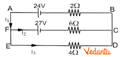
Ans: In the given figure, applying junction rule at point F
$\Rightarrow {{I}_{1}}={{I}_{2}}+{{I}_{3}}$ ……$(1)$
Loop rule for \[BAFCB\]
$\Rightarrow 2{{I}_{1}}+6{{I}_{2}}-24+27=0$
$\Rightarrow 2{{I}_{1}}+6{{I}_{2}}+3=0~$ …… $(2)$
Loop rule for FCDEF
$\Rightarrow 27+6{{I}_{2}}-4{{I}_{3}}=0$ …….$(3)$
Substituting ${{I}_{1}}$ in equation$(2)$
$(2)\Rightarrow 2({{I}_{2}}+{{I}_{3}})+6{{I}_{2}}+3=0~$
$(2)\Rightarrow 2{{I}_{3}}+8{{I}_{2}}+3=0$
$2\times (2)\Rightarrow 2(2{{I}_{3}}+8{{I}_{2}}+3)=0$
$2\times (2)\Rightarrow 4{{I}_{3}}+16{{I}_{2}}+6=0$ …….$(4)$
$(4)+(3)\Rightarrow 27+6+22{{I}_{2}}=0$
$\Rightarrow {{I}_{2}}=\frac{-33}{22}=\frac{-3}{2}$
$\Rightarrow {{I}_{2}}=-1.5A$
Substitute ${{I}_{2}}$ in equation $(2)$
$\Rightarrow 2{{I}_{1}}+6(-1.5)+3=0~$
$\Rightarrow 2{{I}_{1}}=6$
$\Rightarrow {{I}_{1}}=3A$
Substitute ${{I}_{1}},{{I}_{2}}$ in equation $(1)$
$\Rightarrow 3=-1.5+{{I}_{3}}$
$\Rightarrow {{I}_{3}}=4.5A$
Therefore, the currents are ${{I}_{1}}=3A$,${{I}_{2}}=-1.5A$and ${{I}_{3}}=4.5A$.
20. Show that when a current is divided between two resistances in accordance with Kirchhoff’s laws, the heat provided is minimum.
Ans: Consider two resistances ${{R}_{1}},{{R}_{2}}$ in parallel with ${{i}_{1}},{{i}_{2}}$ currents flowing in it. Using Kirchhoff’s first law,
$i={{i}_{1}}+{{i}_{2}}$ ……$(1)$
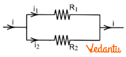
${{i}_{1}}{{R}_{1}}-{{i}_{2}}{{R}_{2}}=0$
$\frac{{{i}_{1}}}{{{i}_{2}}}=\frac{{{R}_{2}}}{{{R}_{1}}}.$
Heat produced in the circuit in $t$ seconds is $H=i_{1}^{2}{{R}_{1}}t+{{i}_{2}}^{2}{{R}_{2}}t$$\Rightarrow H={{i}_{1}}^{2}{{R}_{1}}t+{{\left( i-{{i}_{1}} \right)}^{2}}{{R}_{2}}t$
If the heat produced is minimum then $\frac{dH}{d{{i}_{1}}}=0$
$\Rightarrow 2{{\text{i}}_{1}}{{\text{R}}_{1}}\text{t}+2\left( \text{i}-{{\text{i}}_{1}} \right)(-1){{\text{R}}_{2}}\text{t=0}$
\[\Rightarrow 2\left( \text{i}-{{\text{i}}_{1}} \right){{\text{R}}_{2}}\text{t}=2{{\text{i}}_{1}}{{\text{R}}_{1}}\text{t}\]
\[\Rightarrow \left( i-{{i}_{1}} \right){{R}_{2}}={{i}_{1}}{{R}_{1}}\]
\[\Rightarrow \frac{{{i}_{1}}}{{{i}_{2}}}=\frac{{{R}_{2}}}{{{R}_{1}}}\]
Therefore, it is proved in accordance with Kirchhoff’s law.
21.
(a) Define emf. of a cell? On what factors does it depend?
Ans: Emf of a cell is defined as the potential difference between the two electrodes of the cell in open Circuit (when no current is drawn).
It depends on the following factors:
(a) Nature of Electrodes
(b) Nature and concentration of the Electrolytes
(c) Temperature of the cell.
(b) Figure below shows a $2.0V$ potentiometer used for the determination of internal resistance of a $1.5V$ cell. The balance point of the cell in the open circuit is $76.3cm$. When a resistance of $9.5\Omega $ is used in the external circuit of the cell the balance point shifts to $64.8cm$ length of the potentiometer. Determine the internal resistance of the cell.
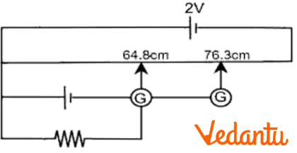
Ans: It is known that,
Internal resistance of the cell, $\text{r}=\text{R}\left( \frac{{{\ell }_{1}}-{{\ell }_{2}}}{{{\ell }_{2}}} \right)$
It is given that,
${{\ell }_{1}}=76.3~\text{cm, }{{\ell }_{2}}=64.8~\text{cm, R}=9.5\Omega $
$\Rightarrow \text{r}=9.5\left( \frac{76.3-64.8}{64.8} \right)$
$\Rightarrow r=1.68\Omega $
Therefore, the internal resistance of the cell, $r=1.68\Omega $.
22. A battery of emf 10 V and internal resistance $3\Omega $ is connected to a resistor. If the current in the circuit is 0.5 A, what is the resistance of the resistor? What is the terminal voltage of the battery when the circuit is closed?
Ans: In the above question it is given that:
Emf of the battery, E = 10 V
Internal resistance of the battery, $r=3\Omega $
Current in the circuit, $I=0.5A$
Consider the resistance of the resistor to be $R$.
Therefore, using Ohm’s law,
$I=\frac{E}{R+r}$
$R+r=\frac{E}{I}$
$\Rightarrow R+r=\frac{10}{0.5}$
$\Rightarrow R+r=20$
$\therefore R=20-3=17\Omega $
Let the terminal voltage of the resistor be $V$.
Using Ohm's law,
$V=IR$
$\Rightarrow V=0.5\times 17=8.5V$
Thus, the resistance of the resistor is $17\Omega $ and the terminal voltage is $8.5V$ .
23.
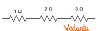
(a) Three resistors $1\Omega $ , $2\Omega $ and $3\Omega $ are combined in series. What is the total resistance of the combination?
Ans: In the above question it is given that three resistors of resistances $1\Omega $ , $2\Omega $ and $3\Omega $ are combined in series.
The total resistance of the combination is the algebraic sum of individual resistances.
Hence the total resistance is given by:
Total Resistance $=1+2+3=6\Omega $
(b) If the combination is connected to a battery of emf $12V$ and negligible internal resistance, obtain the potential drop across each resistor.
Ans: Consider the current flowing through the circuit to be $I$.
Emf of the battery, $E=12V$
Total resistance of the circuit, $R=6\Omega $
The relation for current using Ohm’s law is given by:
$I=\frac{E}{R}$
$\Rightarrow I=\frac{12}{6}=2A$
Consider the potential drop across $1\Omega $ resistor to be ${{V}_{1}}$ .
Using Ohm’s law, the value of ${{V}_{1}}$ can be obtained as:
${{V}_{1}}=2\times 1=2V$ …… (1)
Consider the potential drop across $2\Omega $ resistor to be ${{V}_{2}}$ .
Again, using Ohm’s law, the value of ${{V}_{2}}$ can be obtained as:
${{V}_{2}}=2\times 2=4V$ …… (2)
Consider potential drop across $3\Omega $ resistor to be ${{V}_{3}}$ .
$\therefore {{V}_{3}}=2\times 3=6V$ ...... (3)
Hence, the potential drop across $1\Omega $ , $2\Omega $ and $3\Omega $ resistors are $2V$ , $4V$ and $6V$ respectively.
24. At room temperature ${{27.0}^{\circ }}C$, the resistance of a heating element is $100\Omega $. What is the temperature of the element if the resistance is found to be $117\Omega $, given that the temperature coefficient of the material of the resistor is $1.70\times {{10}^{-4}}^{\circ }{{C}^{-1}}$ ?
Ans: In the above question it is given that:
Room temperature, $T={{27.0}^{\circ }}C$
Resistance of the heating element at $T$ , $R=100\Omega $
Consider ${{T}_{1}}$ as the increased temperature of the filament.
Therefore, resistance of the heating element at ${{T}_{1}}$, ${{R}_{1}}=117\Omega $
Temperature coefficient of the material of the filament, $\alpha =1.70\times {{10}^{-4}}^{\circ }{{C}^{-1}}$
We know that,
$\alpha =\frac{{{R}_{1}}-R}{R\left( {{T}_{1}}-T \right)}$
$\therefore \left( {{T}_{1}}-T \right)=\frac{{{R}_{1}}-R}{R\alpha }$
$\Rightarrow \left( {{T}_{1}}-27 \right)=\frac{117-100}{100\times 1.70\times {{10}^{-4}}}$
$\Rightarrow \left( {{T}_{1}}-27 \right)=1000$
$\therefore {{T}_{1}}={{1027}^{\circ }}C$
Therefore, at ${{1027}^{\circ }}C$ , the resistance of the element is $117\Omega $ .
25. A negligibly small current is passed through a wire of length 15 m and uniform cross-section $6.0\times {{10}^{-7}}{{m}^{2}}$ , and its resistance is measured to be $5.0\Omega $ . What is the resistivity of the material at the temperature of the experiment?
Ans: In the above question it is given that:
Length of the wire, $l=15m$
Area of cross-section of the wire, $a=6.0\times {{10}^{-7}}{{m}^{2}}$
Resistance of the material of the wire, $R=5.0\Omega $
Let resistivity of the material of the wire be $\rho $
We know that resistance is related to resistivity as:
$R=\rho \frac{l}{A}$
$\Rightarrow \rho =\frac{RA}{l}$
$\Rightarrow \rho =\frac{5\times 6.0\times {{10}^{-7}}}{15}$
$\therefore \rho =2\times {{10}^{-7}}{{m}^{2}}$
Therefore, the resistivity of the material is $2\times {{10}^{-7}}{{m}^{2}}$ .
26. A silver wire has a resistance of \[2.1\Omega \] at ${{27.5}^{\circ }}C$ , and a resistance of $2.7\Omega $ at ${{100}^{\circ }}C$. Determine the temperature coefficient of resistivity of silver.
Ans: In the above question it is given that:
Temperature, ${{T}_{1}}={{27.5}^{\circ }}C$.
Resistance of the silver wire at ${{T}_{1}}$ is ${{R}_{1}}=2.1\Omega $ .
Temperature, ${{T}_{2}}={{100}^{\circ }}C$ .
Resistance of the silver wire at ${{T}_{2}}$ is ${{R}_{2}}=2.7\Omega $ .
Let the temperature coefficient of silver be $\alpha $ .
It is related to temperature and resistance by the formula:
$\alpha =\frac{{{R}_{2}}-{{R}_{1}}}{{{R}_{1}}\left( {{T}_{2}}-{{T}_{1}} \right)}$
$\Rightarrow \alpha =\frac{2.7-2.1}{2.1\left( 100-27.5 \right)}={{0.0039}^{\circ }}{{C}^{-1}}$
Hence the temperature coefficient of silver is ${{0.0039}^{\circ }}{{C}^{-1}}$.
27. A heating element using nichrome connected to a 230 V supply draws an initial current of 3.2A which settles after a few seconds to a steady value of 2.8 A. What is the steady temperature of the heating element if the room temperature is ${{27}^{\circ }}C$ ? Temperature coefficient of resistance of nichrome averaged over the temperature range involved is $1.70\times {{10}^{-4}}^{\circ }{{C}^{-1}}$ .
Ans: In the above question it is given that:
Supply voltage is $V=230V$
Initial current drawn is ${{I}_{1}}=3.2A$.
Let the initial resistance be ${{R}_{1}}$ .
Therefore, using Ohm’s law,
${{R}_{1}}=\frac{V}{{{I}_{1}}}$
$\Rightarrow {{R}_{1}}=\frac{230}{3.2}=71.87\Omega $
Steady state value of the current is ${{I}_{2}}=2.8A$.
Let the resistance of the steady state be ${{R}_{2}}$ .
Therefore, using Ohm’s law.
${{R}_{2}}=\frac{V}{{{I}_{2}}}$
$\Rightarrow {{R}_{2}}=\frac{230}{2.8}=82.14\Omega $
Temperature coefficient of nichrome is $\alpha =1.70\times {{10}^{-4}}^{\circ }{{C}^{-1}}$ .
Initial temperature of nichrome is ${{T}_{1}}={{27}^{\circ }}C$.
Let the steady state temperature reached by nichrome be ${{T}_{2}}$ .
Now using the formula of $\alpha $,
$\alpha =\frac{{{R}_{2}}-{{R}_{1}}}{{{R}_{1}}\left( {{T}_{2}}-{{T}_{1}} \right)}$
$\Rightarrow \left( {{T}_{2}}-{{T}_{1}} \right)=\frac{{{R}_{2}}-{{R}_{1}}}{{{R}_{1}}\alpha }$
$\Rightarrow \left( {{T}_{2}}-27 \right)=\frac{82.14-71.87}{71.87\times 1.70\times {{10}^{-4}}}$
$\Rightarrow {{T}_{2}}-27=840.5$
$\therefore {{T}_{2}}={{867.5}^{\circ }}C$
Hence the steady temperature of the heating element is ${{867.5}^{\circ }}C$ .
28. A storage battery of emf 8.0 V and internal resistance $0.5\Omega $ is being charged by a 120 V DC supply using a series resistor of $15.5\Omega $. What is the terminal voltage of the battery during charging? What is the purpose of having a series resistor in the charging circuit?
Ans: In the above question it is given that:
Emf of the storage battery is $E=0.8V$.
Internal resistance of the battery is $r=0.5\Omega $ .
DC supply voltage is $V=120V$
Resistance of the resistor is $R=15.5\Omega $.
Consider effective voltage in the circuit to be $V'$.
$V'=V-E$
$V'=120-8=112V$
Now, the current flowing in the circuit is $I$ and the resistance $R$ is connected in series to the storage battery.
Therefore, using Ohm’s law,
$I=\frac{V'}{R+r}$
$\therefore I=\frac{112}{15.5+0.5}=7A$
Hence voltage across resistor $R$will be:
$IR=7\times 15.5=108.5V$
DC supply voltage = Terminal voltage of battery + Voltage drop across $R$
Terminal voltage of battery $=120-108.5=11.5V$
A series resistor in a charging circuit is responsible for limiting the current drawn from the external source. The current will be extremely high in its absence which is very dangerous.
29. The number density of free electrons in a copper conductor estimated in Example is $8.5\times {{10}^{28}}{{m}^{-3}}$ . How long does an electron take to drift from one end of a wire 3.0 m long to its other end? The area of cross-section of the wire is $2.0\times {{10}^{-6}}{{m}^{2}}$ and it is carrying a current of 3.0 A.
Ans: In the above question it is given that:
Number density of free electrons in a copper conductor is $n=8.5\times {{10}^{28}}{{m}^{-3}}$.
Length of the copper wire is $l=3.0m$.
Area of cross-section of the wire is $A=2.0\times {{10}^{-6}}{{m}^{2}}$.
Current carried by the wire is $I=3.0A$.
Now we know that:
$I=nAe{{V}_{d}}$
Where,
$e$ is the electric charge of magnitude $1.6\times {{10}^{-19}}C$.
${{V}_{d}}$ is the drift velocity and
\[Drift\text{ }velocity=\frac{\text{Length of the wire }\left( \text{l} \right)}{\text{Time taken to cover }\left( \text{t} \right)}\]
$I=nAe\frac{l}{t}$
$\Rightarrow t=\frac{nAel}{I}$
$\Rightarrow t=\frac{3\times 8.5\times {{10}^{28}}\times 2\times {{10}^{-6}}\times 1.6\times {{10}^{-19}}}{3.0}$
$\therefore t=2.7\times {{10}^{4}}s$ .
Hence the time taken by an electron to drift from one end of the wire to the other is $2.7\times {{10}^{4}}s$.
30. The earth’s surface has a negative surface charge density of ${{10}^{-9}}C{{m}^{-2}}$ . The potential difference of $400kV$ between the top of the atmosphere and the surface results (due to the low conductivity of the lower atmosphere) in a current of only $1800A$ over the entire globe. If there were no mechanism of sustaining atmospheric electric fields, how much time (roughly) would be required to neutralize the earth’s surface? (This never happens in practice because there is a mechanism to replenish electric charges, namely the continual thunderstorms and lightning in different parts of the globe). (Radius of earth = $6.37\times {{10}^{6}}m$.)
Ans: In the above question it is given that:
Surface charge density of the earth is $\sigma ={{10}^{-9}}C{{m}^{-2}}$.
Current over the entire globe is $I=1800A$.
Radius of the earth is $r=6.37\times {{10}^{6}}m$.
Surface area of the earth is given by:
$A=4\pi {{r}^{2}}$
$\Rightarrow A=4\pi \times {{\left( 6.37\times {{10}^{6}} \right)}^{2}}$
$\therefore A=5.09\times {{10}^{14}}{{m}^{2}}$
Charge on the earth surface is given by:
$q=\sigma A$
$\Rightarrow q={{10}^{-9}}\times 5.09\times {{10}^{14}}$
$\therefore q=5.09\times {{10}^{5}}C$
Now if time taken to neutralize the earth’s surface is $t$, then
Current, $I=\frac{q}{t}$
$\Rightarrow t=\frac{q}{I}$
$\Rightarrow t=\frac{5.09\times {{10}^{5}}}{1800}=282.77s$
Therefore, the time taken to neutralize the earth’s surface is $282.77s$.
31. Choose the Correct Alternative:
(a) Alloys of metals usually have (greater/less) resistivity than that of their constituent metals.
Ans: Alloys of metals usually have greater resistivity than that of their constituent metals.
(b) Alloys usually have much (lower/higher) temperature coefficients of resistance than pure metals.
Ans: Alloys usually have lower temperature coefficients of resistance than pure metals.
(c) The resistivity of the alloy manganin is nearly independent of/increases rapidly with increase of temperature.
Ans: The resistivity of the alloy, manganin, is nearly independent of increase of temperature.
(d) The resistivity of a typical insulator (e.g., amber) is greater than that of a metal by a factor of the order of $\left( {{10}^{22}}/{{10}^{3}} \right)$.
Ans: The resistivity of a typical insulator is greater than that of a metal by a factor of the order of ${{10}^{22}}$ .
32. Determine the current drawn from a $12V$ supply with internal resistance $0.5\Omega $ by the infinite network shown in Figure. Each resistor has $1\Omega $ resistance.
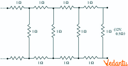
Ans: In the above question it is given that the resistance of each resistor connected in the given circuit is $R=1\Omega $.
Let the equivalent resistance of the given circuit be $R'$.
As the network is infinite the equivalent resistance is given by the relation,
$R'=2+\frac{R'}{\left( R'+1 \right)}$
$\Rightarrow {{\left( R' \right)}^{2}}-2R'-2=0$
$\Rightarrow R'=\frac{2\pm \sqrt{12}}{2}=1\pm \sqrt{3}$
As only positive value is acceptable,
$\therefore R'=1+\sqrt{3}$
Internal resistance of the circuit is $r=0.5\Omega $.
Therefore, total resistance $=2.73+0.5=3.23\Omega $.
Using Ohm’s law,
$I=\frac{V}{R}=\frac{12}{3.23}=3.72A$.
Therefore, the current drawn is $3.72A$.
33. Figure 3.34 shows a potentiometer circuit for comparison of two resistances. The balance point with a standard resistor $R=10.0\Omega $ is found to be \[\mathbf{58}.\mathbf{3cm}\] while that with the unknown resistance $X$ is \[\mathbf{68}.\mathbf{5}\text{ }\mathbf{cm}\]. Determine the value of $X$. What might you do if you failed to find a balance point with the given cell of emf $\varepsilon $ ?
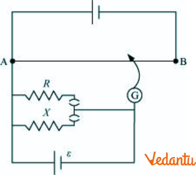
Ans: In the above question it is given that:
Resistance of the standard resistor is $R=10.0\Omega $ .
Balance point for this resistance is at a distance ${{l}_{1}}=58.3cm$.
Current in the potentiometer wire is $i$.
Hence, potential drop across $R$ is ${{E}_{1}}=iR$.
Resistance of the unknown resistor is $X$.
Balance point for this resistance is at a distance ${{l}_{2}}=68.5cm$.
Hence, potential drop across $X$ is ${{E}_{2}}=iX$.
The relation connecting emf and balance point is,
$\frac{{{E}_{1}}}{{{E}_{2}}}=\frac{{{l}_{1}}}{{{l}_{2}}}$
$\Rightarrow \frac{iR}{iX}=\frac{{{l}_{1}}}{{{l}_{2}}}$
$\Rightarrow X=\frac{{{l}_{1}}}{{{l}_{2}}}\times R=\frac{68.5}{58.3}\times 10=11.749\Omega $ .
Therefore, the value of the unknown resistance $X$ is $11.749\Omega $.
If we fail to find a balance point with the given cell of emf $\varepsilon $, then the potential drop across $R$and $X$ is reduced by putting a resistance in series with it.
A balance point is obtained only if the potential drop across $R$ or $X$ is smaller than the potential drop across the potentiometer wire AB.
34. Figure shows a $2.0V$ potentiometer used for the determination of internal resistance of $1.5V$ cell. The balance point of the cell in the open circuit is $76.3cm$. When a resistor of $9.5\Omega $ is used in the external circuit of the cell, the balance point shifts to $64.8cm$ length of the potentiometer wire. Determine the internal resistance of the cell.
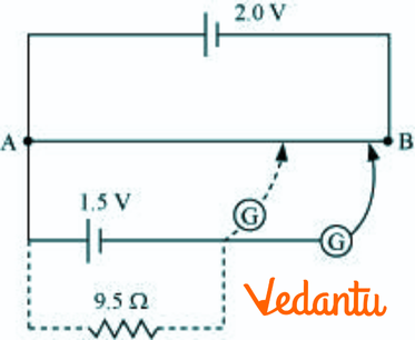
Ans: In the above question it is given that:
Balance point of the cell in the open circuit is ${{l}_{1}}=76.3cm$.
An external resistance $R$ of resistance $9.5\Omega $ is connected to the circuit.
New balance point of the circuit is at a distance ${{l}_{2}}=64.8cm$ .
Current flowing through the circuit $=I$ .
The relation connecting resistance and emf is:
$r=\left( \frac{{{l}_{1}}-{{l}_{2}}}{{{l}_{2}}} \right)R$
$\Rightarrow r=\left( \frac{76.3-64.8}{64.8} \right)9.5=1.68\Omega $
Hence the internal resistance of the cell is $1.68\Omega $ .
Long Answer Questions: (5 Marks)
1.
(a) Three resistors $2\Omega $ , $4\Omega $ and $5\Omega $ are combined in parallel. What is the total resistance of the combination?
Ans: In the above question it is given that there are three resistors of resistances $2\Omega $ , $4\Omega $ and $5\Omega $.
They are connected in parallel.
Hence, total resistance $R$ of the combination will be:
$\frac{1}{R}=\frac{1}{{{R}_{1}}}+\frac{1}{{{R}_{2}}}+\frac{1}{{{R}_{3}}}$
$\Rightarrow \frac{1}{R}=\frac{1}{2}+\frac{1}{4}+\frac{1}{5}=\frac{19}{20}$
$\therefore R=\frac{20}{19}\Omega $
Therefore, total resistance of the combination is $\frac{20}{19}\Omega $ .
(b) If the combination is connected to a battery of emf $20V$ and negligible internal resistance, determine the current through each resistor, and the total current drawn from the battery.
Ans: In the above question it is given that:
Emf of the battery, $V=20V$
Current ${{I}_{1}}$ flowing through resistor ${{R}_{1}}$ is given by:
${{I}_{1}}=\frac{V}{{{R}_{1}}}$
$\Rightarrow {{I}_{1}}=\frac{20}{2}=10A$
Current ${{I}_{2}}$ flowing through resistor ${{R}_{2}}$ is given by:
${{I}_{2}}=\frac{V}{{{R}_{2}}}$
$\Rightarrow {{I}_{2}}=\frac{20}{4}=5A$
Current ${{I}_{3}}$ flowing through resistor ${{R}_{3}}$ is given by:
${{I}_{3}}=\frac{V}{{{R}_{3}}}$
$\Rightarrow {{I}_{3}}=\frac{20}{5}=4A$
Hence the total current will be:
$I={{I}_{1}}+{{I}_{2}}+{{I}_{3}}$
$\therefore I=10+5+4=19A$
Therefore, the current through resistors $2\Omega $ , $4\Omega $ and $5\Omega $ is $10A$ , $5A$ and $4A$ respectively and the total current is $19A$.
2. Determine the current in each branch of the network shown in figure:
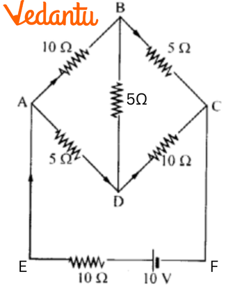
Ans: Current flowing through various branches of the circuit is represented in the given figure.
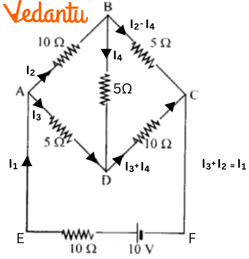
Consider
${{I}_{1}}=$Current flowing through the outer circuit
${{I}_{2}}=$Current flowing through branch AB
${{I}_{3}}=$Current flowing through branch AD
${{I}_{2}}-{{I}_{4}}=$Current flowing through branch BC
${{I}_{3}}+{{I}_{4}}=$Current flowing through branch CD
${{I}_{4}}=$Current flowing through branch BD
For the closed circuit ABDA, potential is zero i.e.,
$10{{I}_{2}}+5{{I}_{4}}-5{{I}_{3}}=0$
$2{{I}_{2}}+{{I}_{4}}-{{I}_{3}}=0$
${{I}_{3}}=2{{I}_{2}}+{{I}_{4}}$ …… (1)
For the closed circuit BCDB, potential is zero i.e.,
$5\left( {{I}_{2}}-{{I}_{4}} \right)-10\left( {{I}_{3}}+{{I}_{4}} \right)-5{{I}_{4}}=0$
$5{{I}_{2}}+5{{I}_{4}}-10{{I}_{3}}-10{{I}_{4}}-5{{I}_{4}}=0$
$5{{I}_{2}}-10{{I}_{3}}-20{{I}_{4}}=0$
${{I}_{2}}=2{{I}_{3}}+4{{I}_{4}}$ …… (2)
For the closed circuit ABCFEA, potential is zero i.e.,
$-10+10\left( {{I}_{1}} \right)+10\left( {{I}_{2}} \right)+5\left( {{I}_{2}}-{{I}_{4}} \right)=0$
$10=15{{I}_{2}}+10{{I}_{1}}-5{{I}_{4}}$
$3{{I}_{3}}+2{{I}_{1}}-{{I}_{4}}=2$ …… (3)
From equations (1) and (2), we obtain
${{I}_{3}}=2\left( 2{{I}_{3}}+4{{I}_{4}} \right)+{{I}_{4}}$
${{I}_{3}}=4{{I}_{3}}+8{{I}_{4}}+{{I}_{4}}$
$-3{{I}_{3}}=9{{I}_{4}}$
$-3{{I}_{4}}=+{{I}_{3}}$ …… (4)
Putting equation (4) in equation (1), we obtain
${{I}_{3}}=2{{I}_{2}}+{{I}_{4}}$
$-4{{I}_{4}}=2{{I}_{2}}$ …… (5)
It is evident from the given figure that,
${{I}_{1}}={{I}_{3}}+{{I}_{2}}$ ……. (6)
Putting equation (6) in equation (1), we obtain
$3{{I}_{2}}+2\left( {{I}_{3}}+{{I}_{2}} \right)-{{I}_{4}}=2$
$5{{I}_{2}}+2{{I}_{3}}-{{I}_{4}}=2$ …… (7)
Putting equations (4) and (5) in equation (7), we obtain
$5\left( -2{{I}_{4}} \right)+2\left( -3{{I}_{4}} \right)-{{I}_{4}}=2$
$-10{{I}_{4}}-6{{I}_{4}}-{{I}_{4}}=2$
$17{{I}_{4}}=-2$
${{I}_{4}}=-\frac{2}{17}A$
Equation (4) reduces to
${{I}_{3}}=-3\left( {{I}_{4}} \right)$
${{I}_{3}}=-3\left( -\frac{2}{17} \right)=\frac{6}{17}A$
${{I}_{2}}=-2\left( {{I}_{4}} \right)$
${{I}_{2}}=-2\left( -\frac{2}{17} \right)=\frac{4}{17}A$
${{I}_{2}}-{{I}_{4}}=\frac{4}{17}-\left( -\frac{2}{17} \right)=\frac{6}{17}$
${{I}_{3}}+{{I}_{4}}=\frac{6}{17}+\left( \frac{-2}{17} \right)=\frac{4}{17}A$
${{I}_{1}}={{I}_{3}}+{{I}_{2}}$
$\therefore {{I}_{1}}=\frac{6}{17}+\frac{4}{17}=\frac{10}{17}A$
Therefore, current in branch AB $=\frac{4}{17}A$
Current in branch BC $=\frac{6}{17}A$
Current in branch CD $=\frac{-4}{17}A$
Current in branch AD $=\frac{6}{17}A$
Current in branch BD $=\left( \frac{-2}{17} \right)A$
Total current $=\frac{4}{17}+\frac{6}{17}+\frac{-4}{17}+\frac{6}{17}+\frac{-2}{17}=\frac{10}{17}A$ .
3.
(a) In a metre bridge [Fig. 3.27], the balance point is found to be at $39.5cm$ from the end A, when the resistor Y is of $12.5\Omega $ . Determine the resistance of $X$. Why are the connections between resistors in a Wheatstone or meter bridge made of thick copper strips?
Ans: A metre bridge with resistors $X$ and $Y$ is represented in the given figure.
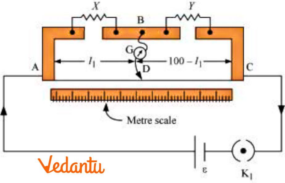
In the above question it is given that:
Balance point from end A is at distance, ${{l}_{1}}=39.5cm$
Resistance of the resistor \[Y=12.5\Omega \] .
Condition for the balance is,
$\frac{X}{Y}=\frac{100-{{l}_{1}}}{{l}_{1}}$
$\therefore X=\frac{100-39.5}{39.5}\times 12.5=8.2\Omega $
Hence, the resistance of resistor $X$ is $8.2\Omega $.
The connection between resistors in a Wheatstone or metre bridge is made of thick copper strips which helps to minimize the resistance. Hence it is not taken into consideration in the bridge formula.
(b) Determine the balance point of the bridge above if $X$ and $Y$are interchanged.
Ans: Now, if $X$ and $Y$are interchanged, then ${{l}_{1}}$ and $100-{{l}_{1}}$ also gets interchanged.
Hence the balance point of the bridge will be $100-{{l}_{1}}$ from $A$.
$\therefore 100-{{l}_{1}}=100-39.5=60.5cm$
Hence, the balance point is $60.5cm$ from $A$.
(c) What happens if the galvanometer and cell are interchanged at the balance point of the bridge? Would the galvanometer show any current?
Ans: When the galvanometer and cell are interchanged at the balance point of the bridge, the galvanometer will show no deflection. As there is zero deflection, no current would flow through the galvanometer.
4.
(a) Six lead-acid types of secondary cells each of emf 2.0 V and internal resistance $0.015\Omega $ are joined in series to provide a supply to a resistance of $8.5\Omega$ . What is the current drawn from the supply and its terminal voltage?
Ans: In the above question it is given that:
Number of secondary cells is $n=6$.
Emf of each secondary cell is $E=2.0V$.
Internal resistance of each cell is $r=0.015\Omega $ .
Series resistor is connected to the combination of cells.
The resistance of the resistor $R$ is $8.5\Omega $.
If the current drawn from the supply is $I$, then
$I=\frac{nE}{R+nr}$
$\Rightarrow I=\frac{6\times 2}{8.5+6\times 0.015}$
$\therefore I=1.39A$
Now the Terminal voltage will be
$V=IR=1.39\times 8.5=11.87V$
Therefore, the current drawn from the supply is $1.39A$ and the terminal voltage is $11.87V$.
(b) A secondary cell after long use has an emf of $1.9V$ and a large internal resistance of $380\Omega $. What maximum current can be drawn from the cell? Could the cell drive the starting motor of a car?
Ans: After long use,
Emf of the secondary cell will be $E=1.9V$.
Internal resistance of the cell is $r=380\Omega $ .
Therefore, maximum current $=\frac{E}{r}$
$\Rightarrow \frac{E}{r}=\frac{1.9}{380}=0.005A$.
Hence the maximum current drawn from the cell is $0.005A$. Since a large current is required to start the motor of a car, the cell cannot be used to start a motor.
5. Two wires of equal length, one of aluminium and the other of copper have the same resistance. Which of the two wires is lighter? Hence explain why aluminium wires are preferred for overhead power cables.
${{\rho }_{Al}}=2.63\times {{10}^{8}}\Omega m$, ${{\rho }_{Cu}}=1.72\times {{10}^{-8}}\Omega m$, $\text{Relative density of Al}=2.7$, $\text{Relative density of Cu}=8.9$
Ans: In the above question it is given that:
Resistivity of aluminium is ${{\rho }_{Al}}=2.63\times {{10}^{8}}\Omega m$.
Relative density of aluminium is ${{d}_{1}}=2.7$.
Consider ${{l}_{1}}$ to be the length of aluminium wire, ${{m}_{1}}$ as its mass, resistance of the copper wire as ${{R}_{2}}$, and area of cross-section of the copper wire as ${{A}_{2}}$.
Therefore,
${{R}_{1}}={{\rho }_{1}}\frac{{{l}_{1}}}{{{A}_{1}}}$ …… (1)
And
${{R}_{2}}={{\rho }_{2}}\frac{{{l}_{2}}}{{{A}_{2}}}$ …… (2)
But we have ${{R}_{1}}={{R}_{2}}$
$\therefore {{\rho }_{1}}\frac{{{l}_{1}}}{{{A}_{1}}}={{\rho }_{2}}\frac{{{l}_{2}}}{{{A}_{2}}}$
Also, we have ${{l}_{1}}={{l}_{2}}$.
\[\therefore \frac{{{\rho }_{1}}}{{{A}_{1}}}=\frac{{{\rho }_{2}}}{{{A}_{2}}}\]
i.e., $\frac{{{A}_{1}}}{{{A}_{2}}}=\frac{{{\rho }_{1}}}{{{\rho }_{2}}}$
$\therefore \frac{{{A}_{1}}}{{{A}_{2}}}=\frac{2.63\times {{10}^{8}}}{1.72\times {{10}^{-8}}}=\frac{2.63}{1.72}$
Now the mass of the aluminium wire is given by:
${{m}_{1}}=Volume\times Density$
$\therefore {{m}_{1}}={{A}_{1}}{{l}_{1}}\times {{d}_{1}}={{A}_{1}}{{l}_{1}}{{d}_{1}}$ …… (3)
Similarly, mass of the copper wire is given by:
${{m}_{2}}=Volume\times Density$
$\therefore {{m}_{2}}={{A}_{2}}{{l}_{2}}\times {{d}_{2}}={{A}_{2}}{{l}_{2}}{{d}_{2}}$ …… (4)
Dividing equation (3) by equation (4), we get:
$\frac{{{m}_{1}}}{{{m}_{2}}}=\frac{{{A}_{1}}{{l}_{1}}{{d}_{1}}}{{{A}_{2}}{{l}_{2}}{{d}_{2}}}$
As ${{l}_{1}}={{l}_{2}}$,
$\frac{{{m}_{1}}}{{{m}_{2}}}=\frac{{{A}_{1}}{{d}_{1}}}{{{A}_{2}}{{d}_{2}}}$
As \[\frac{{{A}_{1}}}{{{A}_{2}}}=\frac{2.63}{1.72}\]
$\frac{{{m}_{1}}}{{{m}_{2}}}=\frac{2.63}{1.72}\times \frac{2.7}{8.9}=0.46$
It indicated that ${{m}_{1}} < {{m}_{2}}$.
Therefore, aluminium is lighter than copper.
Since aluminium is lighter, it is preferred for overhead power cables over copper.
6. Answer the Following Questions:
a. A steady current flow in a metallic conductor of the non-uniform cross section. Which of these quantities is constant along with the conductor: current, current density, electric field, drift speed?
Ans: In the above question it is given that a steady current flows in a metallic conductor of the non-uniform cross-section. Therefore, the current flowing through the conductor is constant.
Current density, electric field, and drift speed are inversely proportional to the area of cross-section. Hence, they are not constant.
b. Is ohm’s law universally applicable for all conducting elements? If not, give examples of elements which do not obey Ohm’s law.
Ans: Ohm’s law is not universally applicable for all conducting elements.
Vacuum diode semiconductor is a non-ohmic conductor. Therefore, Ohm’s law is not valid for it.
c. A low voltage supply from which one needs high currents must have very low internal resistance. Why?
Ans: According to Ohm’s law, $V=IR$ .
It states that Voltage $\left( V \right)$ is directly proportional to current $\left( I \right)$ .
Therefore,
$I=\frac{V}{R}$
where, $R$ is the internal resistance of the source.
If V is low, then R must be very low, for high current drawn from the source.
d. A high tension (HT) supply of, say, 6 kV must have a very large internal resistance. Why?
Ans: A high tension supply of a very large internal resistance is required in order to prohibit the current from exceeding the safety limit.
If the internal resistance is very low, then the current drawn exceeds the safety limits in case of a short circuit.
7.
(a) Given n resistors each of resistance R, how will you combine them to get the (i) maximum (ii) minimum effective resistance? What is the ratio of the maximum to minimum resistance?
Ans: In the above question it is given that the total number of resistors are $n$ where resistance of each resistor is $R$.
i. When $n$ resistors are connected in series the effective resistance will be maximum when it is a product of $nR$ . Hence, maximum resistance of the combination is given by ${{R}_{1}}=nR$ .
ii. The effective resistance is the minimum when resistors are connected in parallel. Therefore, the effective resistance ${{R}_{2}}$ is given by ${{R}_{2}}=\frac{R}{n}$ .
The ratio of the maximum to the minimum resistance will be
$\Rightarrow \frac{{{R}_{1}}}{{{R}_{2}}}=\frac{nR}{R/n}={{n}^{2}}$
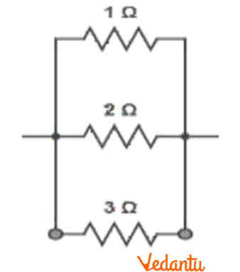
(b) Given the resistances of $1\Omega ,2\Omega ,3\Omega $ , how will you combine them to get an equivalent resistance of (i) $\left( 11/3 \right)\Omega $ (ii) $\left( 11/5 \right)\Omega $ (iii) $6\Omega $ (iv) $\left( 6/11 \right)\Omega $ ?
Ans: In the above question it is given that:
${{R}_{1}}=1\Omega ,{{R}_{2}}=2\Omega ,{{R}_{3}}=3\Omega $
(i) For equivalent resistance of $\left( 11/5 \right)\Omega $:
Consider the circuit diagram given below.
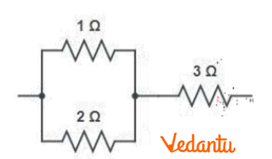
Equivalent resistance for the circuit will be:
$R'=\frac{2\times 1}{2+1}+3=\frac{2}{3}+3=\frac{11}{3}\Omega $
(ii) For equivalent resistance of $\left( 11/3 \right)\Omega $:
Consider the circuit diagram given below.
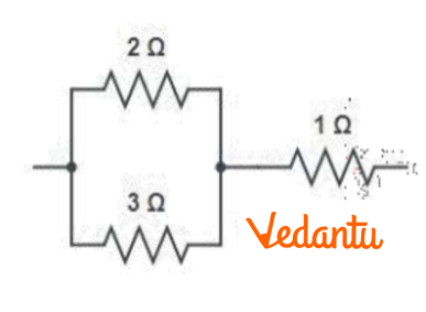
Equivalent resistance for the circuit will be:
$R'=\frac{2\times 3}{2+3}+1=\frac{6}{5}+1=\frac{11}{5}\Omega $
(iii) For equivalent resistance of $6\Omega $:
Consider the circuit diagram given below.
Equivalent resistance for the circuit will be:
$R'=1+2+3=6\Omega $
(iv) For equivalent resistance of $\left( 6/11 \right)\Omega $:
Consider the circuit diagram given below.
Equivalent resistance for the circuit will be:
$R'=\frac{1\times 2\times 3}{1\times 2+2\times 3+3\times 1}=\frac{6}{11}\Omega $
(b)
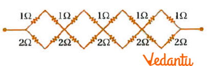
Ans: Consider first small loop, two resistors of resistance $1\Omega $ each are connected in series.
Therefore, their equivalent resistance $=1+1=2\Omega $ .
Now two resistors of resistance $2\Omega $ each are connected in series.
Therefore, their equivalent resistance $=2+2=4\Omega $ .
Hence the circuit is resolved to:
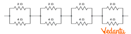
Here $2\Omega $ and $4\Omega $ resistors are connected in parallel in all the four loops.
Therefore, equivalent resistance $R'$ is given by,
$R'=\frac{2\times 4}{2+4}=\frac{8}{6}=\frac{4}{3}\Omega $
The circuit further results into:
Four resistors are connected in series.
Therefore, equivalent resistance of the given circuit will be $\frac{4}{3}\times 4=\frac{16}{3}\Omega $ .
(c)
Ans: In the circuit it is given that five resistors of resistance $R$ are connected in series.
Therefore, equivalent resistance of the circuit $=R+R+R+R+R=5R$ .
8. Figure shows a potentiometer with a cell of $2.0V$ and internal resistance $0.40\Omega $ maintaining a potential drop across the resistor wire AB. A standard cell which maintains a constant emf of $1.02V$ (for very moderate currents up to a few mA) gives a balance point at $67.3cm$ length of the wire. To ensure very low currents drawn from the standard cell, a very high resistance of $600k\Omega $ is put in series with it, which is shorted close to the balance point. The standard cell is then replaced by a cell of unknown emf $\varepsilon $ and the balance point found similarly, turns out to be at $82.3cm$length of the wire.
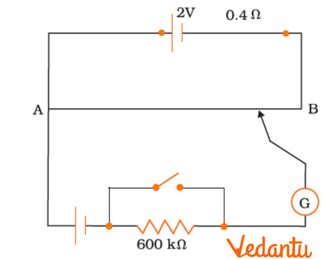
(a) What is the value of $\varepsilon $ ?
Ans: In the above question it is given that constant emf of the given standard cell is ${{E}_{1}}=1.02V$.
The balance point on the wire is at a distance ${{l}_{1}}=67.3cm$.
When the cell of unknown emf $\varepsilon $ is replaced, the standard cell new balance point shifts to $l=82.3cm$.
The relation connecting emf and balance point is,
$\frac{{{E}_{1}}}{{{l}_{1}}}=\frac{\varepsilon }{l}$
$\Rightarrow \varepsilon =\frac{l}{{{l}_{1}}}\times {{E}_{1}}=\frac{82.3}{67.3}\times 1.02=1.247V$
Therefore, the value of unknown emf is $1.247V$.
(b) What purpose does the high resistance of $600k\Omega $ have?
Ans: The purpose of using the high resistance of $600k\Omega $ is to reduce the current through the galvanometer when the movable contact is far from the balance point.
(c) Is the balance point affected by this high resistance?
Ans: The balance point is not affected by the presence of high resistance.
(d) Is the balance point affected by the internal resistance of the driver cell?
Ans: The balance point is not affected by the internal resistance of the driver cell.
(e) Would the method work in the above situation if the driver cell of the potentiometer had an emf of $1.0V$ instead of $2.0V$?
Ans: The method would not work if the driver cell of the potentiometer had an emf of $1.0V$ instead of $2.0V$ because if the emf of the driver cell of the potentiometer is less than the emf of the other cell, then the balance point would not exist on the wire.
(f) Would the circuit work well for determining an extremely small emf, say of the order of a few mV (such as the typical emf of a thermos-couple)? If not, how will you modify the circuit?
Ans: The circuit would not work well for determining an extremely small emf. Due to the instability in the circuit, the balance point would be close to the end A. Hence, there is a large percentage error.
The given circuit can be modified by connecting a series resistance with the wire AB.
The potential drop across AB is slightly greater than the measured emf. The percentage error would be small.
Important Formulas from Class 12 Physics Chapter 3 Current Electricity
Ohm’s Law:\( V = IR \)
-Resistance in Series:\( R_{eq} = R_1 + R_2 + R_3 + \dots \)
Resistance in Parallel:\( \frac{1}{R_{eq}} = \frac{1}{R_1} + \frac{1}{R_2} + \frac{1}{R_3} + \dots \)
Power Dissipated in a Resistor: \( P = I^2R \) or \( P = \frac{V^2}{R} \)
Conductance (G): \( G = \frac{1}{R} \)
Current Density (J): \( J = \frac{I}{A} \)
Drift Velocity (v_d) Relation: \( J = nqv_d \)
Kirchhoff’s Voltage Law (KVL): Sum of potential differences in a closed loop is zero.
Kirchhoff’s Current Law (KCL):Sum of currents at a junction is zero.
Benefits of Class 12 Physics Chapter 3 Current Electricity
Provides the basics required for advanced studies in electrical and electronic engineering.
Concepts like circuit analysis and power dissipation are widely used in electrical devices and systems.
Involves numericals that enhance logical and analytical thinking.
Frequently asked in JEE, NEET, and other entrance exams.
Helps in understanding the working of household electrical systems and safety measures.
Tips to Study Class 12 Physics Chapter 3 Current Electricity Important Questions
Understand and memorise key formulas and their derivations.
Practice numerical problems regularly to build speed and accuracy.
Focus on mastering Kirchhoff’s laws as they form the base for circuit analysis.
Use diagrams to visualise circuits for better comprehension.
Solve previous years' board and competitive exam questions.
Refer to NCERT textbooks and practice the in-text questions thoroughly.
Clarify doubts related to current, resistance, and potential differences.
Make a formula sheet for quick revision before exams.
Watch online tutorials for complex topics if needed.
Test yourself using mock tests and time-bound problem-solving sessions.
Related Study Materials for CBSE Class 12 Physics Chapter 3
Conclusion
The Current Electricity chapter in Class 12 Physics is fundamental for building a strong understanding of electrical principles and circuits. By mastering the important questions with key formulas, and concepts, and solving important questions, students can crack in their board exams and competitive exams. Use this guide to enhance your preparation and gain confidence in this critical topics.
Download CBSE Class 12 Physics Important Questions 2026-27 PDF
Additional Study Materials for Class 12 Physics

FAQs on Important Questions For Class 12 Physics Chapter 3 Current Electricity - 2026-27
1. Which topics from Chapter 3, Current Electricity, are most important for the CBSE Class 12 Physics board exam in 2026-27?
For the Class 12 Physics board exam, the most frequently tested topics from Current Electricity that students must focus on are:
- Kirchhoff’s Laws: Both the junction rule (KCL) and the loop rule (KVL) are crucial. Expect direct numerical problems on complex circuits, often for 3 or 5 marks.
- Potentiometer: Its principle, and applications like comparing EMFs of two cells and finding the internal resistance of a cell, are very important. Derivations and circuit diagrams are frequently asked.
- Wheatstone Bridge and Meter Bridge: Understand the principle of a balanced bridge. Numerical problems to find an unknown resistance are common.
- Drift Velocity and its Relation to Current: The derivation of I = nAevd is a standard 2 or 3-mark question.
- Combination of Resistors and Cells: Problems involving series and parallel combinations, especially for cells (EMF, internal resistance), are important for numericals.
2. What is Kirchhoff's Voltage Law (KVL) and Kirchhoff's Current Law (KCL)? Why are they considered so important for solving circuits?
Kirchhoff's laws are fundamental for analysing electrical circuits where Ohm's law alone is insufficient.
- Kirchhoff’s Current Law (KCL) or Junction Rule: It states that the algebraic sum of electric currents at any junction in a circuit is zero (ΣI = 0). This law is based on the conservation of charge.
- Kirchhoff’s Voltage Law (KVL) or Loop Rule: It states that the algebraic sum of all potential differences (including EMFs and voltage drops across resistors) around any closed loop in a circuit is zero (ΣV = 0). This law is based on the conservation of energy.
They are crucial because they allow us to systematically solve for unknown currents and voltages in complex, multi-loop circuits, which is a guaranteed type of question in board exams.
3. Explain the working principle of a potentiometer. Why is it preferred over a voltmeter for measuring the EMF of a cell?
A potentiometer works on the principle that when a constant current flows through a wire of uniform cross-sectional area and composition, the potential drop across any length of the wire is directly proportional to that length (V ∝ l).
A potentiometer is preferred over a voltmeter for measuring the EMF of a cell because:
- A potentiometer measures the EMF using a null deflection method. At the balance point, it draws no current from the cell whose EMF is being measured.
- The true EMF of a cell is its terminal potential difference when no current is drawn from it. Since the potentiometer meets this condition, it gives a highly accurate measurement of the EMF.
- A voltmeter, on the other hand, must draw some current from the circuit to show a reading, which causes a potential drop across the cell's internal resistance. Therefore, a voltmeter measures the terminal voltage (V = E - Ir), not the actual EMF (E).
4. A wire is stretched to double its original length. What is the effect on its resistance and resistivity? This is a common conceptual question in exams.
This is a classic higher-order thinking (HOTS) question. Here’s the breakdown:
- Resistance: When a wire is stretched to double its length (L' = 2L), its volume (V = A × L) remains constant. To compensate for the increased length, its cross-sectional area (A) must decrease. Since volume is constant, A'L' = AL, which gives A'(2L) = AL, so A' = A/2. The new resistance R' is given by R' = ρ(L'/A') = ρ(2L / (A/2)) = 4(ρL/A) = 4R. Therefore, the resistance becomes four times the original resistance.
- Resistivity (ρ): Resistivity is an intrinsic property of the material itself. It depends only on the nature of the material and its temperature, not on its physical dimensions like length or area. Therefore, when the wire is stretched, its resistivity remains unchanged.
5. What is a balanced Wheatstone bridge? For how many marks is a numerical based on it typically asked?
A Wheatstone bridge is an arrangement of four resistors in a quadrilateral shape, used to determine an unknown resistance. The bridge is said to be balanced when the potential difference between the two points of the galvanometer arm is zero, meaning no current flows through the galvanometer.
The condition for a balanced Wheatstone bridge is:
P/Q = R/S
where P, Q, R, and S are the resistances in the four arms of the bridge. Numerical problems based on this principle, including meter bridge applications, are very common and are typically asked for 2 or 3 marks in the CBSE board exam.
6. How does the resistance of a conductor and a semiconductor change with an increase in temperature? Explain why.
The temperature dependence of resistance is different for conductors and semiconductors, which is an important concept for exams.
- Conductors (Metals): For conductors, resistance increases with an increase in temperature. This is because as temperature rises, the thermal vibrations of the metal ions (kernels) increase. This leads to more frequent collisions between the free electrons and the ions, which decreases the average relaxation time (τ). Since resistance is inversely proportional to relaxation time (R ∝ 1/τ), the resistance increases.
- Semiconductors: For semiconductors, resistance decreases with an increase in temperature. This is because as temperature rises, more electron-hole pairs are generated due to the breaking of covalent bonds. This significantly increases the number density (n) of charge carriers. Although collisions also increase, the effect of the increased number density of charge carriers is much more dominant. Since resistance is inversely proportional to the number density (R ∝ 1/n), the resistance decreases.
7. State and derive the relationship between electric current and drift velocity of electrons. How is this derivation important for exams?
The relationship between electric current (I) and drift velocity (vd) is a fundamental derivation often asked for 2 or 3 marks. The relation is: I = nAevd
Derivation:
Consider a conductor of length L and uniform cross-sectional area A. Let 'n' be the number density of free electrons (number of free electrons per unit volume).
- The total number of free electrons in the conductor is N = (n) × (Volume) = nAL.
- The total charge on these free electrons is Q = N × e = nALe, where 'e' is the charge on one electron.
- The time 't' taken by an electron to travel the length L of the conductor with drift velocity vd is t = L/vd.
- By definition, electric current I is the rate of flow of charge, so I = Q/t.
- Substituting the values of Q and t, we get: I = (nALe) / (L/vd)
- Therefore, I = nAevd. This is the required relation.
8. What is the difference between the EMF of a cell and its terminal potential difference? When are these two quantities equal?
The distinction between EMF and terminal potential difference is a crucial concept for understanding cell circuits.
- EMF (E): Electromotive force is the maximum potential difference between the two terminals of a cell when it is in an open circuit (i.e., when no current is being drawn from it). It represents the total energy supplied by the cell per unit charge.
- Terminal Potential Difference (V): It is the potential difference between the two terminals of a cell when it is in a closed circuit (i.e., when current is being drawn from it). Due to the cell's internal resistance (r), some energy is lost as heat inside the cell. The relationship is given by V = E - Ir, where I is the current.
The EMF (E) and terminal potential difference (V) are equal only when the current (I) drawn from the cell is zero. This happens in an open circuit or when a potentiometer is used to measure the EMF at its balance point.
9. Why are alloys like Manganin and Constantan used for making standard resistance coils and in instruments like the meter bridge?
Alloys such as Manganin and Constantan are preferred for making standard resistors and wires for instruments like meter bridges and potentiometers due to two key properties:
- High Resistivity: They have a much higher resistivity compared to their constituent metals (like copper or manganese). This allows for a required resistance value to be achieved with a shorter, more manageable length of wire.
- Low Temperature Coefficient of Resistance: Their resistance does not change significantly with changes in temperature. This is extremely important for experimental setups where consistent resistance values are needed for accurate measurements, as the flow of current can cause heating (Joule heating).
10. What is an effective strategy for solving complex circuit problems using Kirchhoff's laws in the board exam to avoid errors?
Solving Kirchhoff's law problems requires a systematic approach to avoid sign convention errors and ensure full marks. For the 2026-27 board exam, follow this strategy:
- Step 1: Draw a Clear Diagram: Redraw the circuit if necessary and clearly mark all resistors, EMFs, and junctions.
- Step 2: Assign Current Directions: Assume a direction for the current in each branch. Don't worry if the assumption is wrong; the final answer will simply be negative, indicating the actual direction is opposite. Clearly label them (I₁, I₂, I₃, etc.).
- Step 3: Apply KCL (Junction Rule): Apply the junction rule to one or more junctions to get relations between the currents (e.g., I₁ = I₂ + I₃).
- Step 4: Apply KVL (Loop Rule) and Follow a Consistent Sign Convention: Choose independent loops and traverse them in a single direction (clockwise or anti-clockwise). Stick to a fixed sign convention:
- For EMFs: If you move from the negative to the positive terminal, the EMF is positive. If you move from positive to negative, it is negative.
- For Resistors: If you move in the same direction as the assumed current, the potential drop (IR) is negative. If you move opposite to the current, it is positive.
- Step 5: Solve the Equations: You will have a set of simultaneous linear equations. Solve them carefully to find the values of the unknown currents.