


Electromagnetic Induction Class 12 important questions with answers PDF download
Electromagnetic Induction is a crucial chapter in Class 12 Physics (Chapter 6), providing the foundation for understanding the generation of electricity and its practical applications. This chapter important questions introduce the concepts of Faraday’s laws, Lenz’s law, and the principle of self and mutual induction. With real-world applications like transformers and generators, mastering this topic is essential for scoring well in exams.
 Table of Content
Download the Class 12 Physics Syllabus for detailed coverage and explore our exclusive Class 12 Physics Important Questions PDF to solidify your understanding and crack your exams.


1 Mark Questions
1. A metallic wire coil is stationary in a non – uniform magnetic field.
What is the emf induced in the coil?
Ans: No emf is induced in the coil because there is no change in the magnetic
flux linked with the secondary coil.
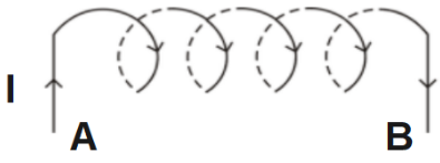
2. Why does metallic piece become very hot when it is surrounded by a coil
carrying high frequency (H.F) alternating current?
Ans: When a metallic piece is surrounded by a coil carrying high frequency
(H.F) alternating current, it becomes hot because eddy currents are produced
which in turn produces joule’s heating effect.
3. An electrical element X when connected to an alternating voltage source
has current through it, leading the voltage by $\frac{\pi }{2}$ radian. Identify X and write an expression for its reactance.
Ans: The X is a purely capacitive circuit.
The expression for capacitive reactance is \[{{X}_{c}}=\frac{1}{\omega C}=\frac{1}{2\pi \upsilon c}\].
4. A transformer steps up $220V$to$2200V$. What is the transformation ratio?
Ans: The transformation ratio, \[K=\frac{{{N}_{S}}}{{{N}_{P}}}=\frac{{{E}_{S}}}{{{E}_{P}}}=\frac{2200}{220}=10\]
Therefore, the transformation ratio is 10.
5. The induced $emf$ is also called back $emf$. Why?
Ans: It is because induced $emf$ produced in a circuit always opposes the cause which produces it.
6. Why the oscillations of a copper disc in a magnetic field are lightly
damped?
Ans: Copper disc oscillates because of the production of eddy currents which
opposes its oscillating motion and as a result the motion gets damped.
7. A metallic wire coil is stationary in a non – uniform magnetic field. What
is the emf. Induced in the coil?
Ans: No emf is induced in the coil as there is no change in the magnetic flux
linked with the secondary coil.
2 Marks Questions
1. If the rate of change of current of \[2A/s\] induces an emf of \[10mV\]in a
solenoid. What is the self-inductance of the solenoid?
Ans: Self-inductance is given by,
\[L=\frac{\varepsilon }{dI/dt}=\frac{10\times {{10}^{-3}}}{2}=5\times {{10}^{-3}}H\]
Therefore, self-inductance of the solenoid is \[5\times {{10}^{-3}}H\].
2. A circular copper disc. \[10cm\] in radius rotates at a speed of \[2\pi rad/s\] about an axis through its centre and perpendicular to the disc. A uniform magnetic field of \[0.2T\] acts perpendicular to the disc.
Calculate the potential difference developed between the axis of the disc and the rim.
Ans: Given, radius \[=10cm\], \[B=0.2T\], \[\omega =2\pi rad/s\]
\[\varepsilon =\frac{1}{2}Bw{{r}^{2}}\]
\[\Rightarrow \varepsilon =\frac{1}{2}\times 0.2\times 2\pi \times {{\left( 0.1 \right)}^{2}}\]
\[\therefore \varepsilon =0.00628volts\]
Therefore, the potential difference developed is \[0.00628volts\].
What is the induced current if the resistance of the disc is \[2\Omega \]?
Ans: \[I=\frac{\varepsilon }{R}=\frac{0.0628}{2}\]
\[\therefore I=0.0314A\]
If the resistance is \[2\Omega \], the induced current is found to be \[0.0314A\].
3. An ideal inductor consumes no electric power in a.c. circuit. Explain?
Ans: Power consumed by inductor in a.c. circuit, \[P=ErmsIrms\cos \phi \]
But for an ideal inductor, \[\phi =\frac{\pi }{2}\]
\[\Rightarrow \cos \phi =\cos \frac{\pi }{2}=0\]
\[\therefore P=0\]
Therefore, an ideal inductor in a.c. circuit does not consume power.
4. Capacitor blocks d.c. why?
Ans: The capacitive reactance, \[{{X}_{c}}=\frac{1}{\omega C}=\frac{1}{2\pi \upsilon c}\]
For d.c., \[\upsilon =0\]
\[\therefore {{X}_{c}}=\propto \]
Since capacitor offers infinite resistance to d.c. flow, d.c. cannot pass through it.
5. Why is the emf zero, when maximum number of magnetic lines of force
pass through the coil?
Ans: The vertical position of the coil offers maximum magnetic flux. But as the coil rotates, \[\frac{d\phi }{dt}=0\]
Therefore, produced emf, \[\varepsilon =\frac{d\phi }{dt}=0\].
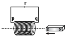
6. An inductor \[L\] of reactance \[{{X}_{L}}\]is connected in series with a bulb B to an a.c. source as shown in the figure.
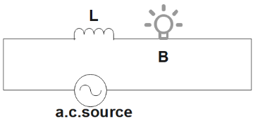
Briefly explain how does the brightness of the bulb change when
Number of turns of the inductor is reduced.
Ans: We know, \[Z=\sqrt{{{R}^{2}}+{{X}_{L}}^{2}}\]
When number of turns of the inductor gets reduced \[{{X}_{L}}\] and Z decreases and in
turn current increases. Because of this the bulb will grow more brightly.
A capacitor of reactance \[{{X}_{C}}={{X}_{L}}\] is included in series in the same circuit.
Ans: When capacitor is included in the circuit, \[Z=\sqrt{{{R}^{2}}+{{\left( {{X}_{L}}-{{X}_{C}} \right)}^{2}}}\]
But, given that, \[{{X}_{C}}={{X}_{L}}\]
That implies at minimum,\[Z=R\]
Therefore, the brightness of the bulb will become maximum.
7. A jet plane is travelling towards west at a speed of \[1800km/hr\]. What is
the voltage difference developed between the ends of the wing having a
span of \[25m\], if the Earth's magnetic field at the location has a magnitude
of \[5\times {{10}^{-4}}T\] and the dip angle is \[{{30}^{\circ }}\].
Ans: Given that, speed of the jet plane, \[v=1800km/h=500m/s\]
Wingspan of jet plane, \[l=25m\]
Earth's magnetic field strength, \[B=5\times {{10}^{-4}}T\]
Angle of dip, \[\delta ={{30}^{\circ }}\]
Vertical component of Earth's magnetic field,
\[{{B}_{v}}=B\sin \delta \]
\[\Rightarrow {{B}_{v}}=5\times {{10}^{-4}}\sin {{30}^{\circ }}\]
\[\Rightarrow 2.5\times {{10}^{-4}}T\]
So, voltage difference between the ends of the wing,
\[e=({{B}_{v}})\times l\times v\]
\[\Rightarrow e=2.5\times {{10}^{-4}}\times 25\times 500\]
\[\therefore 3.125V\]
Therefore, the voltage difference developed between the ends of the wings is
\[3.125V\].
8. A pair of adjacent coils has a mutual inductance of \[1.5H\]. If the current in one coil changes from \[0\] to \[20A\] in \[0.5s\], what is the change of flux linkage with the other coil?
Ans: Given that, mutual inductance of a pair of coils, \[\mu =1.5H\]
Initial current, \[{{I}_{1}}=0A\]
Final current, \[{{I}_{2}}=20A\]
Change in current, \[dI={{I}_{2}}-{{I}_{1}}=20-0=20A\]
Time taken for the change, \[dt=0.5s\]
Induced emf, \[e=\frac{d\phi }{dt}\] \[.....(1)\]
Where, \[d\phi \] is the change in the flux linkages with the coil.
Emf is related with mutual inductance as, \[e=\mu \frac{dl}{dt}\] \[.....(2)\]
Equating equations (1) and (2),
\[\Rightarrow \frac{d\phi }{dt}=\mu \frac{dl}{dt}\]
\[\Rightarrow d\phi =1.5\times (20)\]
\[\therefore d\phi =30Wb\]
Therefore, the change in the flux linkage is \[30Wb\].
9. A horizontal straight wire \[10m\] long extending from east to west is
falling with a speed of \[5.0m{{s}^{-1}}\], at right angles to the horizontal component of the earth's magnetic field, \[0.30\times {{10}^{-4}}Wb{{m}^{-2}}\].
What is the instantaneous value of the emf induced in the wire?
Ans: Given that, length of the wire, \[l=10m\]
Falling speed of the wire, \[v=5.0m/s\]
Magnetic field strength, \[B=0.3\times {{10}^{-4}}Wb{{m}^{-2}}\]
Emf induced in the wire, \[e=Blv\]
\[\Rightarrow e=0.3\times {{10}^{-4}}\times 5\times 10\]
\[\therefore e=1.5\times {{10}^{-3}}V\]
Therefore, instantaneous emf induced is \[1.5\times {{10}^{-3}}V\].
What is the direction of the emf?
Ans: The direction of the induced emf is from West to East by Fleming's right-hand rule.
Which end of the wire is at the higher electrical potential?
Ans: The eastern end of the wire is at higher potential.
10. A \[1.0ms\] long metallic rod is rotated with an angular frequency of
\[400rad{{s}^{-1}}\] about an axis normal to the rod passing through its one end. The other end of the rod is in contact with a circular metallic ring. A constant
and a uniform magnetic field of \[0.5T\] parallel to the axis exists everywhere.
Calculate the emf developed between the centre and the ring.
Ans: From the given data, Length of the rod, \[l=1m\]
Angular frequency, \[\omega =400rad/s\]
Magnetic field strength, \[B=0.5T\]
One end of the rod has zero linear velocity, while the other end has a linear
velocity of \[{{l}_{(t)}}\].
Average linear velocity of the rod, \[v=\frac{{{l}_{(t)}}+0}{2}=\frac{{{l}_{(t)}}}{2}\]
Emf developed between the centre and the ring,
\[e=Blv=Bl\left( \frac{{{l}_{(t)}}}{2} \right)=\frac{B{{l}^{2}}(i)}{2}\]
\[\Rightarrow e=\frac{0.5\times {{(l)}^{2}}\times 400}{2}=100V\]
Therefore, the emf developed between the centre and the ring is \[100V\].
11. Use Lenz’s law to determine the direction of induced current in the
situations described by Figure:
A wire of irregular shape turning into a circular shape;
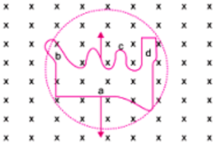
Ans: According to Lenz's law, the direction of the induced emf is such that it tends to produce a current that would oppose the change in the magnetic flux that produced it. The wire here is expanding to form a circle, which means that force would be acting outwards on each part of wire because of the magnetic field (acting in the downwards direction). Now, the direction of induced current should be such that it will produce a magnetic field in the upward direction (towards the reader). Therefore, the force on wire will be towards inward direction, i.e., induced current would be flowing in anticlockwise direction in the loop from cbad.
A circular loop being deformed into a narrow straight wire.
Ans: On deforming the shape of a circular loop into a narrow straight wire, the flux piercing the surface decreases. Therefore, the induced current flows along abcd according to Lenz’s law.
3 Marks Questions
1. How is the mutual inductance of a pair of coils affected when
Separation between the coils is increased.
Ans: When the Separation between the coils is increased, the flux linked with the secondary coils decreases. Therefore, the mutual induction decreases.
The number of turns of each coil is increased.
Ans: As mutual inductance, \[M=\frac{{{\mu }_{0}}{{N}_{1}}{{N}_{2}}A}{l}\];
Therefore, when \[{{N}_{1}}\]and \[{{N}_{2}}\]increases, the mutual induction also increases.
A thin iron sheet is placed between two coils, other factors remaining the same. Explain the answer in each case.
Ans: As mutual inductance, \[M\propto {{\mu }_{r}}\] (Relative permeability of material).
Therefore, mutual induction will increase.
2. Distinguish between resistances, reactance and impedance of an a.c. circuit?
Ans: They can be differentiated as:
3. A sinusoidal voltage,\[V=200\sin 314t\] is applied to a resistor of \[10\Omega \] resistance. Calculate:
$rms$ value of the voltage
Ans: Given that, \[V=200\sin 314t\]
\[V={{V}_{0}}\sin wt\]
\[{{V}_{0}}=200V\]
\[w=314rad/s\]
\[R=10\Omega \]
We have,
\[{{V}_{rms}}=\sqrt{2}{{V}_{0}}\]
\[\therefore {{V}_{rms}}=\sqrt{2}\times 200=282.8V\]
Therefore, the rms value of voltage is \[282.8V\].
$rms$ value of the current
Ans: Rms value of current, \[{{I}_{rms}}=\frac{{{V}_{rms}}}{R}=\frac{282.8}{10}\]
\[\therefore {{I}_{rms}}=28.28A\]
Therefore, the rms value of current is \[28.28A\].
Power dissipated as heat in $watt$.
Ans: Because of purely resistive circuit, flux,\[\phi =0\]
We have,
\[P={{E}_{v}}{{I}_{v}}\cos \phi ={{E}_{V}}{{I}_{V}}\cos 0\]
\[\Rightarrow P={{E}_{v}}{{I}_{v}}=282.8\times 28.28\]
\[\therefore P=7.998watt\]
Therefore, the power dissipated is \[7.998watt\].
4. Obtain an expression for the self-inductance of a long solenoid. Hence define one henry.
Ans: Consider current I flowing through a long solenoid of area A,
Let N be the total number of turns in the solenoid,
Total flux, \[\phi =NBA\]
Here, \[B={{\mu }_{0}}nI\]
Where, n is no. of turns per unit length of the solenoid
\[N=nl\]
\[\Rightarrow \phi =nl\times {{\mu }_{0}}nIA\]
\[\Rightarrow \phi ={{\mu }_{0}}{{n}^{2}}AlI\] \[........(1)\]
Also, \[\phi =LI\] \[........(2)\]
From equation (1) & (2)
\[{{\mu }_{0}}{{n}^{2}} Al {\cancel{I}}=L{\cancel{I}}\]
\[\Rightarrow L={{\mu }_{0}}{{n}^{2}}Al\]
\[\Rightarrow L=\frac{{{\mu }_{0}}{{N}^{2}}A}{l}\]
where,\[\left[ n=N/l \right]\]
One henry(1H) can be defined as: If current is changing at a rate of \[1A/s\] in a coil inducing an emf of \[1volt\]in it, then the inductance of the coil is one henry.
5. A conducting rod rotates with angular speed w with one end at the centre and other end at circumference of a circular metallic ring of radius $R$, about an axis passing through the centre of the coil perpendicular to the plane of the coil A constant magnetic field B parallel to the axis is present everywhere. Show that the emf. between the centre and the metallic ring is \[\frac{1}{2}Bw{{R}^{2}}\].
Ans: If a circular loop connects the centre with point P with a resistor,
The potential difference across the \[\text{resistor}=\text{induced emf}\text{.}\]
\[\varepsilon =B\times \text{Rate of change of area of loop}\]
If the resistor QP is rotated with angular velocity \[\omega \] and turns by an angle \[\theta \] in
time \[\text{t}\] then,
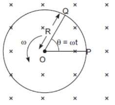
Area swept,
\[\text{A=}\frac{1}{2}\times R\times R\theta \]
\[\Rightarrow A=\frac{1}{2}{{R}^{2}}\theta \]
Now, we have,
\[\phi =BA\cos {{\theta }^{\circ }}=BA\]
\[\Rightarrow \phi =B\times \frac{1}{2}{{R}^{2}}\theta \]
So, \[\varepsilon =\frac{d\phi }{dt}=\frac{d}{dt}\left( \frac{1}{2}B{{R}^{2}}\theta \right)=\frac{1}{2}B{{R}^{2}}\left( \frac{d\theta }{dt} \right)\]
\[\therefore \varepsilon =\frac{1}{2}B\omega {{R}^{2}}\]
Therefore, it is proved that the emf. between the centre and the metallic ring is
\[\frac{1}{2}B\omega {{R}^{2}}\].
6.
At a very high frequency of a.c., a capacitor behaves as a conductor. Why?
Ans: As capacitive Reactance, \[{{X}_{C}}=\frac{1}{2\pi \upsilon c}\]
For a.c. when \[\upsilon \to \infty {{X}_{C}}=0\]
Therefore, at a very high frequency of a.c. the capacitor behaves as a conductor.
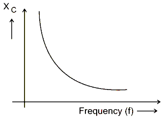
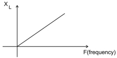
Draw the graph showing the variation of reactance of
(i) A capacitor
(ii) An inductor with a frequency of an a.c. circuit.
Ans: As capacitive Reactance, \[{{X}_{C}}=\frac{1}{2\pi \upsilon c}\]
\[\Rightarrow {{X}_{C}}\propto \frac{1}{\upsilon }\]
So, the corresponding graph would be:
And, inductive reactance, \[{{X}_{L}}=\omega L=2\pi \upsilon L\]
\[\Rightarrow {{X}_{L}}\propto \upsilon \]
Therefore, the corresponding graph here will be,
7. Calculate the current drawn by the primary of a transformer which steps down \[200V\] to \[20V\] to operate a device of resistance \[20\Omega \]. Assume the efficiency of the transformer to be \[80%\].
Ans: Given that, \[\eta =80%\]
\[{{E}_{p}}=200V\]
\[{{E}_{s}}=20V\]
\[Z=20\Omega \]
\[{{I}_{s}}=\frac{{{E}_{s}}}{Z}=\frac{20}{20}=1A\]
Now, we have,
\[\eta =\frac{{{E}_{s}}{{I}_{s}}}{{{E}_{p}}{{I}_{p}}}\]
Substituting the given values,
\[\eta =\frac{80}{100}=\frac{20\times 1}{200\times {{I}_{p}}}\]
\[\Rightarrow {{I}_{p}}=\frac{2000}{80\times 200}\]
\[\therefore {{I}_{p}}=0.125A\]
Therefore, the current drawn by the primary of the transformer is found to be \[0.125A\].
8. An a.c. voltage \[E={{E}_{0}}\sin \omega t\] is applied across an inductance $L$. Obtain the expression for current $I$.
Ans: Given that, \[E={{E}_{0}}\sin \omega t\]
Emf produced across \[L=\frac{-LdI}{dt}\]
Total emf of the circuit \[=E+\left( \frac{-LdI}{dt} \right)\]
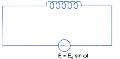
As there is no circuit element across whose potential drop may occur,
\[\Rightarrow E+\left( \frac{-LdI}{dt} \right)=0\]
\[\Rightarrow E=\frac{LdI}{dt}\]
\[\Rightarrow dI=\frac{E}{L}dt\]
\[\Rightarrow dI=\frac{{{E}_{0}}}{L}\sin \omega tdt\]
On Integrating,
\[I=\frac{{{E}_{0}}}{L}\int{\sin \omega tdt}\]
\[\Rightarrow I=\frac{{{E}_{0}}}{L}\left( \frac{-\cos \omega t}{\omega } \right)\]
\[\Rightarrow I=\frac{-{{E}_{0}}}{wL}\cos \omega t\]
\[\Rightarrow I=\frac{{{E}_{0}}}{wL}\sin \left( \omega t-\frac{\pi }{2} \right)\]
\[\Rightarrow I=\frac{{{E}_{0}}}{{{X}_{L}}}\sin \left( \omega t-\frac{\pi }{2} \right)\]
Where, \[\frac{{{E}_{0}}}{{{X}_{L}}}={{I}_{0}}\] (maximum value of current)
\[\therefore I={{I}_{0}}\sin \left( \omega t-\frac{\pi }{2} \right)\]
Therefore, the expression for current is \[I={{I}_{0}}\sin \left( \omega t-\frac{\pi }{2} \right)\].
9. A series circuit with \[L=0.12H\], \[C=0.48mF\] and \[R=25\Omega \] is connected to a \[220V\] variable frequency supply. At what frequency is the circuit current maximum?
Ans: Given that, \[L=0.12H\]
\[C=0.48mF=0.48\times {{10}^{-3}}F\]
\[{{E}_{v}}=220V\]
\[{{I}_{v}}=\frac{{{E}_{v}}}{\sqrt{{{R}^{2}}+{{\left( {{X}_{L}}-{{X}_{C}} \right)}^{2}}}}\]
In the circuit when I is maximum, R will be minimum
\[\Rightarrow {{X}_{L}}={{X}_{C}}\]
\[\Rightarrow I=\frac{{{E}_{v}}}{R}\]
Now, we have,
\[f=\frac{1}{2\pi \sqrt{LC}}=\frac{1}{2\times 3.14\sqrt{0.12\times 0.48\times {{10}^{-3}}}}\]
\[\therefore f=21Hz\]
Therefore, the frequency with maximum circuit current is \[21Hz\].
10. A rectangular wire loop of sides \[8cm\] and \[2cm\] with a small cut is moving out of a region of uniform magnetic field of magnitude \[0.3T\] directed normal to the loop. What is the emf developed across the cut if the velocity of the loop is \[1cm{{s}^{-1}}\] in a direction normal to the
Longer side,
Ans: Given that, length of the rectangular wire, \[l=8cm=0.08m\]
Width of the rectangular wire, \[b=2cm=0.02m\]
So, area of the rectangular loop,
\[A=lb=0.09\times 0.02\]
\[\Rightarrow 16\times {{10}^{-4}}{{m}^{2}}\]
Magnetic field strength, \[B=0.3T\]
Velocity of the loop, \[v=1cm/s=0.01m/s\]
Emf developed in the loop is given as:
\[e=Blv\]
\[\Rightarrow 0.3\times 0.08\times 0.01=2.4\times {{10}^{-4}}V\]
Time taken to travel along the width is,
\[\therefore t=\frac{\text{Distance travelled}}{Velocity}=\frac{b}{v}=\frac{0.02}{0.01}=2s\]
Therefore, the induced voltage is \[2.4\times {{10}^{-4}}V\] which lasts for \[2s\].
shorter side of the loop? For how long does the induced voltage last in each case?
Ans: Emf developed, \[e=Bbv\]
\[\Rightarrow 0.3\times 0.02\times 0.01=0.6\times {{10}^{-4}}V\]
Time taken to travel along the length,
\[\therefore t=\frac{\text{Distance travelled}}{Velocity}=\frac{1}{v}=\frac{0.08}{0.01}=8s\]
Therefore, the induced voltage is \[0.6\times {{10}^{-4}}V\] which lasts for \[8s\].
11. Current in a circuit falls from \[5.0A\] to \[0.0A\] in \[0.1s\]. If an average emf of \[200V\] induced, give an estimate of the self-inductance of the circuit.
Ans: Given that, initial current, \[{{I}_{1}}=5.0A\]
Final current, \[{{I}_{2}}=0.0A\]
Change in current, \[dl={{l}_{1}}-{{l}_{2}}=5A\]
Time taken for the change, \[t=0.1s\]
Average emf, \[e=200V\]
For self-inductance (L) of the coil, we have the relation for average emf as,
\[e=L\frac{di}{dt}s\]
\[\Rightarrow L=\frac{r}{\left( \frac{di}{dt} \right)}\]
\[\therefore \frac{200}{\frac{5}{0.1}}=4H\]
Therefore, the self-induction of the coil is \[4H\].
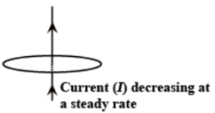
12. Suppose the loop in Exercise 6.4 is stationary but the current feeding the electromagnet that produces the magnetic field is gradually reduced so that the field decreases from its initial value of \[0.3T\] at the rate of \[0.02T{{s}^{-1}}\]. If the cut is joined and the loop has a resistance of \[1.6\Omega \] how much power is dissipated by the loop as heat? What is the source of this power?
Ans: Given that, sides of the rectangular loop are \[8cm\] and \[2cm\].
So, area of the rectangular wire loop, \[A=length\times width\]
\[\Rightarrow A=8\times 2=16c{{m}^{2}}\]
\[\Rightarrow A=16\times {{10}^{-4}}{{m}^{2}}\]
Initial value of the magnetic field, \[B'=0.3T\]
Rate of decrease of the magnetic field, \[\frac{dB}{dt}=0.02T/s\]
Emf developed in the loop is given as:
\[e=\frac{d\phi }{dt}\]
\[d\phi =\text{Change in flux through the loop area}\]
\[\Rightarrow d\phi =d\left( AB \right)\]
\[\Rightarrow e=\frac{d\left( AB \right)}{dt}=\frac{AdB}{dt}\]
\[\Rightarrow e=16\times {{10}^{-4}}\times 0.02=0.32\times {{10}^{-4}}V\]
Resistance of the loop, \[R=1.6\Omega \]
The current induced in the loop is given as:
\[i=\frac{r}{R}\]
\[\Rightarrow i=\frac{0.32\times {{10}^{-4}}}{1.6}=2\times {{10}^{-5}}A\]
Power dissipated in the loop in the form of heat is given as:
\[P={{i}^{2}}R\]
\[\Rightarrow {{\left( 2\times {{10}^{-5}} \right)}^{2}}\times 1.6\]
\[\therefore P=6.4\times {{10}^{-10}}W\]
Therefore, power dissipated in loop as heat is \[6.4\times {{10}^{-10}}W\]. The source of this
heat loss is an external agent, changing the magnetic field with time.
13. An air-cored solenoid with length \[30cm\], area of cross-section \[25c{{m}^{2}}\]and number of turns \[500\], carries a current of \[2.5A\]. The current is suddenly switched off in a brief time of \[{{10}^{-3}}s\]. How much is the average back emf induced across the ends of the open switch in the circuit? Ignore the variation in magnetic field near the ends of the solenoid.
Ans: Given that, length of the solenoid, \[l=30cm=0.3m\]
Area of cross-section, \[A=25c{{m}^{2}}=25\times {{10}^{-4}}{{m}^{2}}\]
Number of turns on the solenoid, \[N=500\]
Current in the solenoid, \[I=2.5A\]
Current flows for time, \[t={{10}^{-3}}s\]
Average back emf,
\[e=\frac{d\phi }{dt}\] \[.........\left( 1 \right)\]
Where,
\[d\phi =\text{Change in flux}\]
\[d\phi =NAB\] \[..........\left( 2 \right)\]
Where,
\[B=\text{Magnetic field strength}\]
\[B={{\mu }_{0}}\frac{Nl}{l}\] \[..........\left( 3 \right)\]
Where,
\[{{\mu }_{0}}=\text{Permeablity of free space}=4n\times {{10}^{-7}}sTm{{A}^{-1}}\]
Using equations (2) and (3) in equation (1), we get,
\[e=\frac{{{\mu }_{0}}{{N}^{2}}lA}{lt}\]
\[\therefore e=\frac{4\pi \times {{10}^{-7}}\times {{\left( 500 \right)}^{2}}\times 2.5\times 25\times {{10}^{-4}}}{0.3\times {{10}^{-3}}}=6.5V\]
Therefore, the average back emf induced in the solenoid is \[6.5V\].
14. A line charge \[\lambda \] per unit length is lodged uniformly onto the rim of a wheel of mass $M$ and radius $R$. The wheel has light non-conducting spokes and is free to rotate without friction about its axis (Fig. 6.22). A uniform magnetic field extends over a circular region within the rim. It is given by, \[B=-{{B}_{0}}k\] \[\left( r\le a;a<R \right)=0\](otherwise) What is the angular velocity of the wheel after the field is suddenly switched off?
Ans: Given that, line charge per unit length,
\[\Rightarrow \lambda =\frac{\text{Total charge}}{Length}=\frac{Q}{2\pi r}\]
Where,
\[r=\]Distance of the point within the wheel
Mass of the wheel \[=M\]
Radius of the wheel \[=R\]
Magnetic field, \[B=-\vec{B}={{B}_{0}}\hat{k}\]
At distance r, the magnetic force is balanced by the centripetal force, that is,
\[BQv=\frac{M{{v}^{2}}}{r}\]
Where
\[v=\]linear velocity of the wheel
\[\Rightarrow B2\pi r\lambda {{r}^{2}}=\frac{Mv}{r}\]
\[\Rightarrow v=\frac{B2\pi r\lambda {{r}^{2}}}{M}\]
\[\Rightarrow BQv=\frac{M{{v}^{2}}}{r}\]
So Angular velocity,
\[\omega =\frac{v}{R}=\frac{B2\pi r\lambda {{r}^{2}}}{M}\]
For \[r\le \] and \[a<R\] we get,
\[\therefore \omega =-\frac{2{{B}_{0}}{{a}^{2}}\lambda }{MR}k\]
Therefore, the angular velocity of the wheel is \[-\frac{2{{B}_{0}}{{a}^{2}}\lambda }{MR}k\].
5 Marks Questions
1.
State the condition under which the phenomenon of resonance occurs in a series LCR circuit. Plot a graph showing the variation of current with frequency of a.c. sources in a series LCR circuit.
Ans: A series LCR circuit will have resonance when,
\[{{X}_{L}}={{X}_{C}}\]
The variation of current with frequency of a.c. source in series LCR circuit,
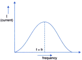
Show that in a series LCR circuit connected to an a.c. source exhibits resonance at its natural frequency equal to \[\frac{1}{\sqrt{LC}}\].
Ans: In a series LCR circuit Electrical resonance takes place when the circuit allows maximum alternating current for which,
\[{{X}_{L}}={{X}_{C}}\]
Impedance, \[Z=\sqrt{{{R}^{2}}+{{\left( {{X}_{L}}-{{X}_{C}} \right)}^{2}}}\]
\[I=\frac{E}{Z}-\frac{E}{\sqrt{{{R}^{2}}+{{\left( {{X}_{L}}-{{X}_{C}} \right)}^{2}}}}\]
For electrical resonance,
\[{{X}_{L}}={{X}_{C}}\]
\[\omega L=\frac{1}{\omega C}\] or \[{{\omega }^{2}}=\frac{1}{LC}\]
\[\therefore \omega =\frac{1}{\sqrt{LC}}\]
Where $\omega $ is the natural frequency of the circuit.
Therefore, a series LCR circuit connected to an a.c. source exhibits resonance at its natural frequency equal to \[\frac{1}{\sqrt{LC}}\].
2. In a step up transformer, the transformation ratio is \[100\]. The primary
voltage is \[200V\] and input is \[1000watt\]. The number of turns in primary is \[100\]. Calculate
Number of turns in the secondary
Ans: Given that, \[k=100\]
\[{{E}_{P}}=200V\]
\[{{E}_{P}}{{I}_{P}}=1000W\]
\[{{N}_{P}}=100\]
\[K=100=\frac{{{N}_{S}}}{{{N}_{P}}}\]
\[\Rightarrow {{N}_{S}}=100\times {{N}_{P}}\]
\[\Rightarrow {{N}_{S}}=100\times 100\]
\[\therefore {{N}_{S}}=10000\]
Current in the primary
Ans: From, \[{{E}_{P}}{{I}_{P}}=1000W\]
\[\Rightarrow {{I}_{P}}=\frac{1000}{{{E}_{P}}}\]
\[\Rightarrow {{I}_{P}}=\frac{1000}{200}=5A\]
\[\therefore {{I}_{P}}=5A\]
The voltage across the secondary
Ans: We know, \[\frac{{{E}_{S}}}{{{E}_{P}}}=\frac{{{N}_{S}}}{{{N}_{P}}}\]
\[\Rightarrow {{E}_{S}}={{E}_{P}}\times \frac{{{N}_{S}}}{{{N}_{P}}}\]
\[\Rightarrow {{E}_{S}}=200\times 100\]
\[\therefore {{E}_{S}}=20000Volt\]
Current in the secondary
Ans: We know, \[\frac{{{E}_{S}}}{{{E}_{P}}}=\frac{{{I}_{P}}}{{{I}_{S}}}\]
\[\therefore {{I}_{S}}=\frac{{{I}_{P}}{{E}_{P}}}{{{E}_{S}}}\]
\[\Rightarrow {{I}_{S}}=\frac{1000}{20000}=\frac{1}{20}\]
\[\therefore {{I}_{S}}=0.05A\]
Write the formula for the transformation ratio.
Ans: For step up transformer; \[K>1\], that is, \[K=\frac{{{N}_{S}}}{{{N}_{P}}}\]. Therefore, the
transformation ratio is \[\frac{{{N}_{S}}}{{{N}_{P}}}\].
3. Derive an expression for the average power consumed in a.c. series LCR circuit. Hence define the power factor.
Ans: Consider an a.c. series circuit,
\[E={{E}_{0}}\sin \omega t\]
And \[I={{I}_{0}}\sin \left( \omega t+\phi \right)\]
Where \[\phi \] is the phase angle by which current leads the emf.
Now using, \[dw=EIdt\]
\[\Rightarrow dw=({{E}_{0}}\sin \omega t)({{I}_{0}}\sin \omega t+\phi )dt\]
\[\Rightarrow dw={{E}_{0}}{{I}_{0}}\sin \omega t(\sin \omega t\cos \phi +\cos \omega t\sin \phi )dt\]
\[\Rightarrow dw={{E}_{0}}{{I}_{0}}({{\sin }^{2}}\omega t\cos \phi +\sin \omega t\cos \omega t\sin \phi )dt\] \[\left[ \because \sin 2\omega t=2\sin \omega t\cos \omega t \right]\]
\[\Rightarrow dw={{E}_{0}}{{I}_{0}}\left( \frac{1-\cos 2\omega t}{2}\cos \phi +\frac{\sin 2\omega t}{2}\sin \phi \right)\]
\[\left[ \therefore {{\sin }^{2}}\omega t=\frac{1-\cos 2\omega t}{2} \right]\]
\[\Rightarrow dw=\frac{{{E}_{0}}{{I}_{0}}}{2}(\cos \phi -\cos \phi \cos 2\omega t+\sin \phi \sin 2\omega t)dt\]
Integrating within limits \[t=0\] to \[t=T\]
\[W=\frac{{{E}_{0}}{{I}_{0}}}{2}\left[ \cos \phi \int\limits_{0}^{T}{dt-\cos \phi \int\limits_{0}^{T}{\cos 2\omega tdt+\sin \phi \int\limits_{0}^{T}{\sin 2\omega tdt}}} \right]\]
\[\Rightarrow W=\frac{{{E}_{0}}{{I}_{0}}}{2}\cos \phi \int\limits_{0}^{T}{dt}\] \[\left[ \because \int\limits_{0}^{T}{\sin 2\omega tdt=}\int\limits_{0}^{T}{\cos 2\omega tdt}=0 \right]\]
\[\Rightarrow W=\frac{{{E}_{0}}{{I}_{0}}}{2}T\cos \phi \]
Therefore, average power consumed in a.c circuit is given by
\[{{P}_{av}}=\frac{W}{T}=\frac{{{E}_{0}}{{I}_{0}}}{2}\cos \phi \]
\[\Rightarrow {{P}_{av}}={{E}_{V}}{{I}_{V}}\cos \phi \] \[........(1)\]
In the above expression, \[\cos \phi \] is termed as power factor.
When the power factor, \[\cos \phi =1\phi ={{0}^{\circ }}\],
It means the circuit is purely resistive and \[{{P}_{av}}={{E}_{V}}{{I}_{V}}\].
When \[\cos \phi =0\], \[\phi ={{90}^{\circ }}\],
It means the circuit is purely capacitive or inductive. That is \[{{P}_{av}}=0\].
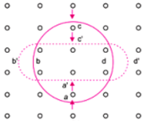
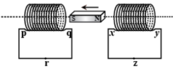
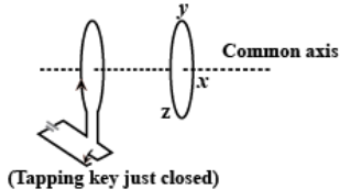
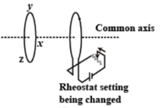
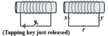
4. Predict the direction of induced current in the situations described by the following figures (a) to (f).
Ans: The direction of the induced current in a closed loop could be given by Lenz’s law. The following pairs of figures show the direction of the induced current when the North pole of a bar magnet is moved towards and away from a closed loop respectively.
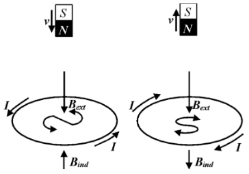
Now, by using Lenz’s rule, the direction of the induced current in the given situation is found to be along qrpq.
Ans: On using Lenz’s law, we find the direction of the induced current here to be along prqp.
Ans: Using Lenz’s law, we find the direction of the induced current to be along yzxy.
Ans: Using Lenz’s law, we find the direction of the induced current to be along zyxz.
Ans: Using Lenz’s law, we found the direction of the induced current to be along xryx.
Ans: Here we find that, no current is induced since the field lines are lying in the same plane as that of the closed loop.
5. A long solenoid with 15 turns per cm has a small loop of area $2.0c{{m}^{2}}$
placed inside the solenoid normal to its axis. If the current carried by the
solenoid changes steadily from \[2.0A\] to \[4.0A\]in\[0.1s\], what is the induced
emf in the loop while the current is changing?
Ans: We are given the following information:
Number of turns on the solenoid \[=15turns/cm=1500turns/m\]
Number of turns per unit length, \[n=1500\text{ }turns\]
The solenoid has a small loop of area,$A=2.0c{{m}^{2}}=2\times {{10}^{-4}}{{m}^{2}}$
Current carried by the solenoid changes from\[2A\text{ }to\text{ }4A\].
Now, the change in current in the solenoid, \[di=4-2=2A\]
Change in time, \[dt=0.1\text{ }s\]
Induced emf in the solenoid could be given by Faraday’s law as:
$\varepsilon =\frac{d\phi }{dt}$………………………… (1)
Where, induced flux through the small loop, $\phi =BA$…………… (2)
Equation (1) would now reduce to:
$\varepsilon =\frac{d}{dt}\left( BA \right)=A{{\mu }_{0}}n\times \left( \frac{di}{dt} \right)$
Substituting the given values into this equation, we get,
$\varepsilon =2\times {{10}^{-4}}\times 4\pi \times {{10}^{-7}}\times 1500\times \frac{2}{0.1}$
$\therefore \varepsilon =7.54\times {{10}^{-6}}V$
Therefore, the induced voltage in the loop is found to be, $\varepsilon =7.54\times {{10}^{-6}}V$.
6. A circular coil of radius \[8.0cm\]and 20 turns is rotated about its vertical
diameter with an angular speed of $50rad{{s}^{-1}}$in a uniform horizontal
magnetic field of magnitude $3.0\times {{10}^{-2}}T$. Obtain the maximum and average emf induced in the coil. If the coil forms a closed loop of resistance\[10\Omega \], calculate the maximum value of current in the coil. Calculate the average power loss due to Joule heating. Where does this power come from?
Ans: We are given:
Max induced emf \[=0.603V\]
Average induced emf \[=0V\]
Max current in the coil \[=0.0603A\]
Average power loss \[=0.018W\text{ }\](Power comes from the external rotor)
Radius of the circular coil, \[r=8cm=0.08m\]
Area of the coil, $A=\pi {{r}^{2}}=\pi \times {{\left( 0.08 \right)}^{2}}{{m}^{2}}$
Number of turns on the coil, \[N=20\]
Angular speed, $\omega =50rad/s$
Magnetic field strength, $B=3\times {{10}^{-2}}T$
Resistance of the loop, \[R=10\text{ }\Omega \]
Maximum induced emf could be given as:
$\varepsilon =N\omega AB=20\times 50\times \pi \times {{\left( 0.08 \right)}^{2}}\times 3\times {{10}^{-2}}$
$\therefore \varepsilon =0.603V$
The maximum emf induced in the coil is found to be \[0.603V\].
Over a full cycle, the average emf induced in the coil is found to be zero.
Maximum current is given as:
$I=\frac{\varepsilon }{R}$
$\Rightarrow I=\frac{0.603}{10}$
$\Rightarrow I=0.0603A$
Average power loss due to joule heating:
$\therefore P=\frac{eI}{2}=\frac{0.603\times 0.0603}{2}=0.018W$
We know that the current induced in the coil would produce a torque opposing the rotation of the coil. Since, the rotor is an external agent, it must supply a torque to counter this torque in order to keep the coil rotating uniformly.
Hence, dissipated power comes from the external rotor.
7. A square loop of side \[12cm\] with its sides parallel to X and Y axes is
moved with a velocity of \[18cm\] in the positive x-direction in an
environment containing a magnetic field in the positive z-direction. The
field is neither uniform in space nor constant in time. It has a gradient of
${{10}^{-3}}Tc{{m}^{-1}}$ along the negative x-direction (that is it increases by ${{10}^{-3}}Tc{{m}^{-1}}$ as one moves in the negative x-direction), and it is decreasing in time at the rate of ${{10}^{-3}}T{{s}^{-1}}$. Determine the direction and magnitude of the induced current in the loop if its resistance is\[4.50m\Omega \].
Ans: We are given,
Side of the square loop, \[s=12cm=0.12m\]
Area of the square loop, $A=0.12\times 0.12=0.0144{{m}^{2}}$
Velocity of the loop, \[v=8cm/s=0.08m/s\]
Gradient of the magnetic field along negative x-direction,
$\frac{dB}{dx}={{10}^{-3}}Tc{{m}^{-1}}={{10}^{-1}}T{{m}^{-1}}$
And, rate of decrease of the magnetic field,
$\frac{dB}{dt}={{10}^{-3}}T{{s}^{-1}}$
Resistance of the loop,
$R=4.5m\Omega =4.5\times {{10}^{-3}}\Omega $
Rate of change of the magnetic flux due to the motion of the loop in a non-uniform magnetic field is given as:
\[\frac{d\phi }{dt}= A\times\frac{dB}{dx}\times v\]
$\Rightarrow \frac{d\phi }{dt}=144\times {{10}^{-4}}{{m}^{2}}\times {{10}^{-1}}\times 0.08$
$\Rightarrow \frac{d\phi }{dt}=11.52\times {{10}^{-5}}T{{m}^{2}}{{s}^{-1}}$
Rate of change of the flux due to explicit time variation in field B is given as:
$\frac{d\phi '}{dt}=A\times \frac{dB}{dx}$
$\Rightarrow \frac{d\phi '}{dt}=144\times {{10}^{-4}}\times {{10}^{-3}}=1.44\times {{10}^{-5}}T{{m}^{2}}{{s}^{-1}}$
Since the rate of change of the flux is the induced emf, the total induced emf in the loop can be calculated as:
\[e=1.44\times {{10}^{-5}}+11.52\times {{10}^{-5}}\]
\[=12.96\times {{10}^{-5}}V\]
\[\therefore \text{Induced current, }i=\frac{e}{R}\]
\[\Rightarrow i=\frac{12.96\times {{10}^{-5}}}{4.5\times {{10}^{-3}}}\]
\[\therefore i=2.88\times {{10}^{-2}}A\]
Therefore, the direction of the induced current is such that there is an increase in the flux through the loop along the positive z-direction.
8. It is desired to measure the magnitude of field between the poles of a
powerful loudspeaker magnet. A small flat search coil of area \[2c{{m}^{2}}\]with 25 closely wound turns, is positioned normal to the field direction, and then
quickly snatched out of the field region. Equivalently, one can give it a quick \[{{90}^{\circ }}\] turn to bring its plane parallel to the field direction). The total
charge flown in the coil (measured by a ballistic galvanometer connected to
coil) is\[7.5mC\]. The combined resistance of the coil and the galvanometer is
\[0.50\Omega \]. Estimate the field strength of the magnet.
Ans: We are given the following:
Area of the small flat search coil, \[A=2c{{m}^{2}}=2\times {{10}^{-4}}{{m}^{2}}\]
Number of turns on the coil, \[N=25\]
Total charge flowing in the coil, \[Q=7.5mC=7.5\times {{10}^{-3}}C\]
Total resistance of the coil and galvanometer, \[R=0.50\Omega \]
Induced current in the coil,
\[I=\frac{\text{Induced emf}(\varepsilon )}{R}\]……………………………………………. (1)
Induced \[emf\] is given as:
\[\varepsilon =-N\frac{d\phi }{dt}\]………………………………………………… (2)
Where, \[d\phi =\text{Induced flux}\]
Combining equations (1) and (2), we get
\[I=-\frac{N\frac{d\phi }{dt}}{R}\]
\[Idt=-\frac{N}{R}d\phi \]……………………………………………. (3)
Initial flux through the coil, \[{{\phi }_{i}}=BA\]
Where,
\[B=\text{Magnetic field strength}\]
Final flux through the coil, \[{{\phi }_{f}}=0\]
Integrating equation (3) on both sides, we have
\[\int{Idt=-\frac{N}{R}\int\limits_{{{\phi }_{i}}}^{{{\phi }_{f}}}{d\phi }}\]
But the total charge could be given as, \[Q=\int{Idt}\]
\[\Rightarrow Q=\frac{-N}{R}({{\phi }_{f}}-{{\phi }_{i}})=\frac{-N}{R}(-{{\phi }_{i}})=\frac{+N{{\phi }_{i}}}{R}\]
\[Q=\frac{NBA}{R}\]
\[\Rightarrow B=\frac{QR}{NA}\]
Substituting the given values, we get,
\[\Rightarrow B=\frac{7.5\times {{10}^{-3}}\times 0.5}{25\times 2\times {{10}^{-4}}}\]
\[\therefore B=0.75T\]
Therefore, the field strength of the magnet is found to be \[0.75T\].
9. Figure shows a metal rod PQ resting on the smooth rails AB and
positioned between the poles of a permanent magnet. The rails, the rod,
and the magnetic field are in three mutual perpendicular directions. A
galvanometer G connects the rails through a switch K. Length of the rod
\[=15cm\], \[B=0.50T\], resistance of the closed loop containing the rod
\[=9.0m\Omega \]. Assume the field to be uniform.
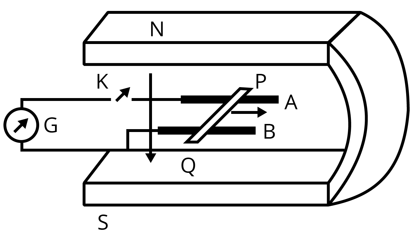
Suppose K is open and the rod is moved with a speed of \[12cm\cdot {{s}^{-1}}\] in the direction shown. Give the polarity and magnitude of the induced \[emf\].
Ans: We are given:
Length of the rod, \[l=15cm=0.15m\]
Magnetic field strength, \[B=0.50T\]
Resistance of the closed loop, \[R=9m\Omega =9\times {{10}^{-3}}\Omega \]
Induced \[emf=9mV\]
Here, the polarity of the induced \[emf\] is such that end P shows positive while end Q shows negative ends.
Speed of the rod,\[v=12cm/s=0.12m/s\]
We know that the induced \[emf\] could be given as: \[\varepsilon =Bvl\]
Substituting the given values, we get,
\[\varepsilon =0.5\times 0.12\times 0.15\]
\[\Rightarrow \varepsilon =9\times {{10}^{-3}}v\]
\[\therefore \varepsilon =9mV\]
Therefore, the magnitude of the induced emf is found to be \[\varepsilon =9mV\] and the polarity of the induced emf is such that end P shows positive while end Q shows negative.
Is there an excess charge built up at the ends of the rods when K is open? What if K is closed?
Ans: Yes; when key K is closed, excess charge could be maintained by the continuous flow of current. When key K is open, there is excess charge built up at both rod ends but when key K is closed, excess charge is maintained by the continuous flow of current.
With K open and the rod moving uniformly, there is no net force on the electrons in the rod PQ even though they do experience magnetic force due to the motion of the rod. Explain.
Ans: Magnetic force is cancelled by the electric force that is set-up due to the excess charge of opposite nature at both rod ends. There is no net force on the electrons in rod PQ when key K is open and the rod moves uniformly. This is because magnetic force is cancelled by the electric force set-up due to the excess charge of opposite nature at both ends of the rods.
What is the retarding force on the rod when K is closed?
Ans: We know that the retarding force exerted on the rod could be given by, \[F=IBl\]
Where,
\[I=\text{Current flowing through the rod}\]
Substituting the given values, we get,
\[I=\frac{e}{R}=\frac{9\times {{10}^{-3}}}{9\times {{10}^{-3}}}=1A\]
\[\Rightarrow F=1\times 0.5\times 0.15\]
\[\therefore F=75\times {{10}^{-3}}N\]
Therefore, the retarding force on the rod when the key K is closed is:
\[F=75\times {{10}^{-3}}N\]
How much power is required (by an external agent) to keep the rod moving at the same speed \[(=12cm\cdot {{s}^{-1}})\] when K is closed? How much power is required when K is open?
Ans: We are given:
Speed of the rod, \[v=12cm/s=0.12m/s\]
Now, power could be given as:
\[P=Fv\]
Substituting the given values, we get,
\[\Rightarrow P=75\times {{10}^{-3}}\times 0.12\]
\[\Rightarrow P=9\times {{10}^{-3}}W\]
\[\therefore P=9mW\]
Therefore, we found the power that is required (by an external agent) to keep
the rod moving at the same speed \[(=12cm\cdot {{s}^{-1}})\] when K is closed to be
\[P=9mW\]and when key K is open, no power is expended.
How much power is dissipated as heat in the closed circuit? What is the source of this power?
Ans: We know that,
\[\text{Power dissipated as heat , P=}{{I}^{2}}R\]
\[\Rightarrow P={{(1)}^{2}}\times 9\times {{10}^{-3}}\]
\[\therefore P=9mW\]
The power dissipated as heat in the closed circuit is found to be \[P=9mW\] and
the source of this power is found to be an external agent.
What is the induced \[emf\] in the moving rod if the magnetic field is parallel to the rails instead of being perpendicular?
Ans: In this case, no \[emf\]would be induced in the coil because the motion of the rod does not cut across the field lines.
10.
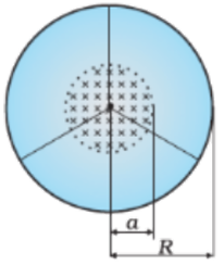
Obtain an expression for the mutual inductance between a long straight wire and a square loop of side a as shown in below figure.
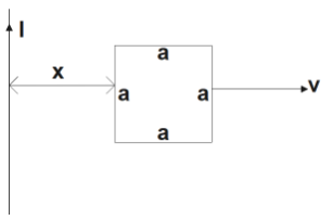
Ans: Consider a small element \[dy\] in the loop at a distance y from the long straight wire (as shown in the given figure).
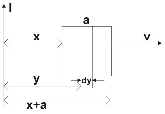
Magnetic flux associated with element \[dy,d\phi =BdA\]
Where, \[dA=\text{Area of element }dy=\text{a }dy\]
\[B=\text{magnetic field at distance y =}\frac{{{\mu }_{0}}I}{2\pi y}\]
\[I=\text{Current in the wire}\]
\[{{\mu }_{0}}=\text{Permeability of free space}=4\pi \times {{10}^{-7}}H/m\]
Carrying out the substitutions accordingly, we get,
\[\Rightarrow d\phi =\frac{{{\mu }_{0}}Ia}{2\pi }\frac{dy}{y}\]
\[\Rightarrow \phi =\frac{{{\mu }_{0}}Ia}{2\pi }\int{\frac{dy}{y}}\]
Now, the limit of y will be from x to \[a+x\], on applying the limits we get,
\[\Rightarrow \phi =\frac{{{\mu }_{0}}Ia}{2x}\int\limits_{x}^{a+x}{\frac{dy}{y}}\]
\[\Rightarrow \phi =\frac{{{\mu }_{0}}Ia}{2\pi }\left[ {{\log }_{e}}y \right]_{x}^{a+x}\]
\[\Rightarrow \phi =\frac{{{\mu }_{0}}Ia}{2\pi }{{\log }_{e}}\left( \frac{a+x}{x} \right)\]
For mutual inductance M, the flux could be given as:
\[\phi =MI\]
\[\Rightarrow MI=\frac{{{\mu }_{0}}Ia}{2\pi }{{\log }_{e}}\left( \frac{a}{x}+1 \right)\]
\[\therefore M=\frac{{{\mu }_{0}}a}{2\pi }{{\log }_{e}}\left( \frac{a}{x}+1 \right)\]
Therefore, the expression for the mutual inductance between the given long
straight wire and the square loop of side a is found to be,
\[M=\frac{{{\mu }_{0}}a}{2\pi }{{\log }_{e}}\left( \frac{a}{x}+1 \right)\]
Now assume that the straight wire carries a current of \[50A\] and the loop is moved to the right with a constant velocity, \[v=10m/s\]. Calculate the induced \[emf\] in the loop at the instant when\[x=0.2m\]. Take \[a=0.1m\] and assume that the loop has a large resistance.
Ans: We know that, the \[Emf\]induced in the loop, \[\varepsilon =B'av=\left( \frac{{{\mu }_{0}}I}{2\pi x} \right)av\]
We are given the following,
\[I=50A\]
\[x=0.2m\]
\[a=0.1m\]
\[v=10m/s\]
On substituting the given values into the equation, we get,
\[\varepsilon =\frac{4\pi \times {{10}^{-7}}\times 50\times 0.1\times 10}{2\pi \times 0.2}\]
\[\therefore \varepsilon =5\times {{10}^{-5}}V\]
Therefore, induced \[emf\] in the loop at the given instant is found to be,
\[\varepsilon =5\times {{10}^{-5}}V\].
Important Formulas from Class 12 Physics Chapter 6 Electromagnetic Induction
Faraday’s Law of Induction:
$\mathcal{E} = - \frac{d\Phi_B}{dt}$
where $\mathcal{E} $ is the induced electromotive force (emf), and $\Phi_B$ is the magnetic flux. The negative sign indicates Lenz's Law, which states that the induced emf opposes the change in magnetic flux.
Magnetic Flux:
$\Phi_B = B A \cos\theta$
where $ΦB\Phi_BΦB$ is the magnetic flux, BBB is the magnetic field, AAA is the area through which the field lines pass, and $θ\thetaθ$ is the angle between the magnetic field and the normal to the surface.
Induced EMF in a Coil:
$\mathcal{E} = -N \frac{d\Phi}{dt}$
where:
$\mathcal{E}$ = induced electromotive force (V)
$N$ = number of turns in the coil
$\Phi$ = magnetic flux (Wb)
$\dfrac{d\Phi}{dt}$ = rate of change of magnetic flux
Lenz’s Law:
$\mathcal{E} = -N \frac{d\Phi}{dt}$
The negative sign represents this opposition, ensuring that the induced current creates a magnetic field opposing the original flux change.
Energy Stored in an Inductor:
$U = \frac{1}{2} L I^2$
where:
$U$ = energy stored (J)
$L$ = inductance (H)
$I$ = current through the inductor (A)
Self-inductance:
$L = \frac{N \Phi}{I}$
where:,
$L$ = self-inductance (H)
$N$ = number of turns in the coil
$\Phi$ = magnetic flux (Wb)
$I$ = current (A)
Mutual inductance:
$M = \frac{N_2 \Phi_2}{I_1}$
where,
$M$ = mutual inductance (H)
$N_2$ = number of turns in the second coil
$\Phi_2$ = magnetic flux linked with the second coil (Wb)
$I_1$ = current in the first coil (A)
The power in AC circuits:
$P = V_{\text{rms}} I_{\text{rms}} \cos\phi$
where,
$P$ = average power (W)
$V_{\text{rms}}$ = root mean square voltage (V)
$I_{\text{rms}}$ = root mean square current (A)
$\phi$ = phase angle between voltage and current
The term $\cos\phi$ is the power factor, which determines the real power delivered to the circuit.
Benefits of Class 12 Physics Chapter 6 Electromagnetic Induction
Builds conceptual understanding for competitive exams like JEE, NEET, etc.
Strengthens knowledge of real-life applications such as electric generators, transformers, and induction stoves.
Lays the groundwork for advanced studies in electromagnetism and electronics.
Enhances problem-solving skills with derivations and numerical questions.
Provides insight into renewable energy technologies like wind and hydroelectric power.
Tips to Study Class 12 Physics Chapter 6 Electromagnetic Induction Important Questions
Understand and memoriSe all formulas and derivations.
Focus on visualizing concepts using diagrams and animations.
Solve NCERT textbook exercises and past year board exam questions.
Practice numerical problems to strengthen application-based knowledge.
Regularly revise key topics like Faraday’s laws, Lenz’s law, and applications of induction.
Refer to supplementary materials for challenging problems.
Related Study Materials for CBSE Class 12 Physics Chapter 6
Conclusion
Electromagnetic Induction is a fascinating and vital chapter that bridges theoretical physics with practical applications. Mastering this chapter ensures a strong grip on concepts for board exams and lays the foundation for further studies. Use this guide, practice smoothly, and make the most of the FREE PDF to crack your exams.
Download CBSE Class 12 Physics Important Questions 2026-27 PDF
Additional Study Materials for Class 12 Physics

FAQs on Important Questions For Class 12 Physics Chapter 6 Electromagnetic Induction - 2026-27
1. What are the most important topics in Chapter 6, Electromagnetic Induction, for the CBSE Class 12 Board Exam 2026-27?
For the Class 12 Board Exam, the most crucial topics in Electromagnetic Induction are:
- Faraday's Laws and Lenz's Law: These form the conceptual backbone and are often tested in 1 or 2-mark questions.
- Motional EMF: Derivations and numerical problems on EMF induced in moving conductors are very common.
- Self and Mutual Inductance: Expect definitions, S.I. units, and numericals. The derivation for the self-inductance of a solenoid is a frequent 3-mark question.
- AC Generator: The principle, construction, and working, along with the derivation of the induced EMF, is a potential 5-mark question.
- Eddy Currents: Conceptual questions on its applications and disadvantages are often asked.
2. How should I use these important questions for Chapter 6 to score well in my Physics exam?
To maximise your score using these questions, follow a strategic approach:
- Test Your Concepts: Start with the 1-mark and 2-mark questions to quickly check if your understanding of fundamental concepts like Lenz's Law and magnetic flux is clear.
- Practice Numericals: Move to the 3-mark questions, which are often numericals. This helps in applying formulas for motional EMF, inductance, and transformers under exam-like conditions.
- Master Derivations: Dedicate focused time to the 5-mark questions, which typically include long derivations like that of an AC generator. Practice writing them step-by-step.
- Identify Weak Areas: Whichever question you find difficult, revisit that topic in your NCERT textbook immediately.
3. Why is Lenz's Law considered a consequence of the law of conservation of energy?
Lenz's Law states that the direction of induced current is always such that it opposes the change in magnetic flux that produced it. This opposition is a direct manifestation of the law of conservation of energy. If the induced current were to aid the change, it would create a bigger change, leading to a larger current, and so on. This would create energy from nothing, which is impossible. Therefore, to induce a current, mechanical work must be done against the opposing force, and this work is converted into electrical energy, upholding the principle of energy conservation.
4. What types of numerical problems are frequently asked from Electromagnetic Induction?
Based on previous board paper trends, you can expect numericals based on the following formulas:
- Calculating induced EMF in a straight conductor moving in a magnetic field (e = Blv).
- Calculating induced EMF in a rotating coil or rod (e = 1/2 BωR²).
- Problems on self-inductance (L) and mutual inductance (M), often involving solenoids.
- Calculating flux change and induced EMF using Faraday's Law (ε = -dΦ/dt).
- Calculations related to transformers, including transformation ratio (K), efficiency, and current/voltage in primary and secondary coils.
5. A metallic piece gets hot when placed in a high-frequency AC field, but not in a steady magnetic field. Why is this an important concept for board exams?
This phenomenon is due to eddy currents. A steady magnetic field (like from a DC source) does not cause a change in magnetic flux, so no current is induced. However, a high-frequency AC field creates a rapidly changing magnetic flux. This induces large, circulating currents (eddy currents) within the metallic piece. Due to the metal's resistance, this large current produces significant heat (Joule's heating effect). This concept is important for exams as it tests the core principle that induction requires a change in flux and has practical applications like induction furnaces and electromagnetic brakes, which are often asked as 1 or 2-mark conceptual questions.
6. Which derivations from Chapter 6 are essential for scoring full marks in a 5-mark question?
For the 5-mark section, mastering the following derivations from Electromagnetic Induction is crucial:
- Expression for the induced EMF in a rotating coil in a uniform magnetic field, which is the principle of an AC Generator.
- Expression for the self-inductance of a long solenoid.
- Expression for the mutual inductance of a pair of co-axial solenoids.
- Derivation for the EMF induced in a conducting rod rotating in a uniform magnetic field.
Always draw a neat, labelled diagram with your derivation to score full marks.
7. What is the key difference between self-inductance and mutual-inductance, and how is this difference tested in exams?
The key difference lies in the source of the magnetic flux change:
- Self-Inductance (L) is the property of a single coil to oppose a change in the current flowing *through itself*. The changing flux is produced by the coil's own current.
- Mutual-Inductance (M) is the property of a pair of coils where a change in current in one coil induces an EMF in the *other* coil.
In exams, this is tested through:
- Definitions and Units: 1-mark questions asking to define the terms and their S.I. unit (Henry).
- Conceptual Questions: Asking for factors affecting L and M.
- Numerical Problems: You must identify from the problem statement whether it involves a single coil (use L) or two coils (use M).
8. What kind of 1-mark or MCQ-type questions can I expect from the topic of transformers?
For 1-mark or MCQ questions on transformers, be prepared for:
- Principle: The working principle of a transformer is mutual induction.
- Transformation Ratio (K): Simple calculations using K = Ns/Np = Vs/Vp.
- Ideal Transformer: The condition for an ideal transformer (efficiency is 100%, no power loss) and the relation IpVp = IsVs.
- Identification: Identifying a transformer as step-up (Ns > Np) or step-down (Np > Ns).
- Core Type: Why a soft iron core is used (to concentrate magnetic flux).
9. Why is the concept of 'back EMF' in an inductor crucial for understanding circuits, and how might it appear as a HOTS question?
Back EMF is the self-induced EMF in an inductor that opposes any change in the current flowing through it. It's crucial because it gives the inductor its property of electrical inertia, resisting sudden changes in current. A common Higher Order Thinking Skills (HOTS) question based on this is: "Explain why a large spark is observed at the switch when a circuit with a large inductor is suddenly switched off." The answer is that when the circuit is broken, the current collapses rapidly. The inductor generates a very large back EMF to oppose this change, which can be high enough to ionise the air across the switch gap, causing a visible spark.
10. Is it sufficient to only practice these important questions for Chapter 6?
While these important questions are excellent for understanding the CBSE exam pattern, identifying high-weightage topics, and targeted practice, they should not be your only resource. For a complete preparation:
- First, build a strong conceptual foundation by thoroughly studying the NCERT textbook.
- Then, use this list of important questions to test your knowledge, practice application, and master the art of writing answers as per the board's expectations.
- Combining NCERT with these questions ensures both deep understanding and exam-readiness.