


Alternating Current Class 12 extra questions and answers free PDF download
Alternating Current Chapter 7 of Class 12 Physics is a cornerstone topic that explains how AC circuits work and their real-world applications. This chapter covers key concepts like RMS values, phase differences, and the functioning of AC devices such as transformers and oscillators. Understanding AC is crucial for board and competitive exams like JEE and NEET.
 Table of Content
Download the Class 12 Physics Syllabus for detailed coverage and explore our exclusive Class 12 Physics Important Questions PDF to solidify your understanding and crack your exams.


1 Mark Questions
1. Power factor of an a.c. circuit is $0.5$. What will be the phase difference between voltage and current in the circuit?
Ans: It is given that,
$\cos \phi =0.5$
$\Rightarrow \phi ={{\cos }^{-1}}\left( 0.5 \right)={{\cos }^{-1}}\left( \frac{1}{2} \right)$
$\Rightarrow \phi ={{60}^{\circ }}$
Therefore, the phase difference is ${{60}^{\circ }}$.
2. Weber is the unit of which physical quantity? Hence define it.
Ans: The SI unit of magnetic flux is Weber.
Weber is defined as the magnetic flux that, linking a circuit of one turn, would produce in it an electromotive force of 1 volt if it were reduced to zero at a uniform rate in 1 second.
3. Two identical loops, one of copper and another of aluminium are rotated with the same speed in the same magnetic field. In which case, the induced
emf.
current will be more and why?
Ans: The induced emf will be the same in both the loops but induced current will be more in the copper loop because its resistance is less.
4. Why the transformer cannot be used to step up d.c. voltage?
Ans: If a d.c voltage source is applied across the primary coil of the transformer, the current in the primary coil remains constant.
Therefore, there is no change in the magnetic flux linked with the secondary coil. So, the voltage across the secondary coil is zero.
Hence, a transformer can't step up dc voltage.
2 Marks Questions
1. Magnet is moved in the direction indicated by an arrow between two coils AB and CD as shown in the figure. Suggest the direction of current in each coil.
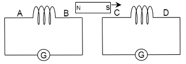
Ans: When a magnet is moved in the given direction, the north pole of the magnet is moved away from the coil AB. Therefore, from Lenz law, the face of coil AB nearest to the North-pole will act like a south pole.
So, the current in coil AB will flow in a clockwise direction when seen from the B-side of the coil. Therefore, the direction of current in coil AB is from A to B.
When the magnet is moved, the south pole of the magnet is moved towards the coil CD. Therefore, to oppose the induced emf, the face of the coil near the South-pole will act as South-pole.
So, the current in the coil CD will flow in anti-clockwise direction when seen from the D-side of the coil. Therefore, the direction of current in coil CD is D to C.
2. How does the self induction of a coil change when
The number of turns in a coil is decreased?
Ans: It is known that,
\[Self\text{ }inductance\text{ }of\text{ }a\text{ }coil<{{N}^{2}}\]
Therefore, if the number of turns in a coil is decreased then, the self inductance of the coil decreases.
An iron rod is introduced into it? Justify.
Ans: When an iron rod is introduced in the coil, the self-inductance of the coil increases.
3. A coil of inductance $L$, a capacitor of capacitance $C$ and a resistor of resistance $R$ are all put in series with an alternating source of emf $E={{E}_{0}}\sin \omega t$. Write an expression for the
Total impedance of the circuit
Ans: Total impedance of the circuit, $Z=\sqrt{{{R}^{2}}+{{\left( {{X}_{L}}-{{X}_{C}} \right)}^{2}}}$
Frequency of the source emf for which the current carrying circuit will show resonance.
Ans: Frequency at resonance, $f=\frac{1}{2\pi \sqrt{LC}}$
4. Obtain the resonant frequency ${{\omega }_{r}}$ of a series LCR circuit with $L=2.0H$, $C=32\mu F$ and $R=10\Omega $ . What is the $\phi $-value of this current?
Ans: It is given that,
Inductance, $L=2H$
Capacitance, \[C=32\mu F=32\times {{10}^{-6}}F\]
$R=10\Omega $
It is known that,
Resonant frequency, ${{\omega }_{r}}=\frac{1}{\sqrt{LC}}$
$\Rightarrow {{\omega }_{r}}=\frac{1}{\sqrt{2\times 32\times {{10}^{-6}}}}$
$\Rightarrow {{\omega }_{r}}=\frac{1}{8\times {{10}^{-3}}}$
$\Rightarrow {{\omega }_{r}}=125{rad}/{s}\;$
$\phi -value=\frac{{{\omega }_{r}}L}{R}$
$\Rightarrow \phi =\frac{1}{R}\sqrt{\frac{L}{C}}$
$\Rightarrow \phi =\frac{1}{10}\sqrt{\frac{2}{32\times {{10}^{-6}}}}$
$\Rightarrow \phi =\frac{1}{10\times 4\times {{10}^{-3}}}$
$\Rightarrow \phi =25$
Therefore, the resonant frequency is $125rad/s$ and $\phi $-value is $25$.
5. A $100\Omega $ resistor is connected to a $220V$, $50Hz$ ac supply.
What is the rms value of current in the circuit?
Ans: It is given that,
Resistance, $R=100\Omega $
Voltage, $V=220V$
Frequency, $f=50Hz$
It is known that,
${{I}_{rms}}=\frac{{{V}_{rms}}}{R}$
$\Rightarrow {{I}_{rms}}=\frac{220}{100}=2.20A$
Therefore, the rms value of current in the circuit is${{I}_{rms}}=2.20A$.
What is the net power consumed over a full cycle?
Ans: It is known that,
$Power=V\times I$
$\Rightarrow Power=220\times 2.2$
$\Rightarrow Power=484W$
Therefore, the net power consumed over a full cycle is$484W$.
6.
The peak voltage of an ac supply is $300V$. What is the rms voltage?
Ans: It is given that,
Peak voltage of the ac supply, ${{V}_{0}}=300V$
It is known that,
${{V}_{rms}}=\frac{{{V}_{0}}}{\sqrt{2}}$
$\Rightarrow {{V}_{rms}}=\frac{300}{\sqrt{2}}$
$\Rightarrow {{V}_{rms}}=212.1V$
Therefore, the rms voltage is $212.1V$.
The rms value of current in an ac circuit is $10A$. What is the peak current?
Ans: It is given that,
Rms value of current in an ac circuit, ${{I}_{rms}}=10A$
It is known that,
${{I}_{0}}=\sqrt{2}\times {{I}_{rms}}$
$\Rightarrow {{I}_{0}}=1.414\times 10$
$\Rightarrow {{I}_{0}}=14.14A$
Therefore, the peak current is $14.14A$.
7. A $44mH$ inductor is connected to $220V$,$50Hz$ ac supply. Determine the rms value of the current in the circuit.
Ans: It is known that,
Inductance, $L=44mH=44\times {{10}^{-3}}H$
Voltage,$V=220V$
Frequency, ${{f}_{L}}=50Hz$
Angular frequency, ${{\omega }_{L}}=2\pi {{f}_{L}}$
It is known that,
Inductive reactance, ${{X}_{L}}={{\omega }_{L}}L=2\pi {{f}_{L}}L$
$\Rightarrow {{X}_{L}}=2\times 3.14\times 50\times 44\times {{10}^{-3}}\Omega $
$\Rightarrow {{X}_{L}}=13.8\Omega $
${{I}_{rms}}=\frac{V}{{{X}_{L}}}$
$\Rightarrow {{I}_{rms}}=\frac{220}{13.82}$
$\Rightarrow {{I}_{rms}}=15.92A$
Therefore, the rms value of the current in the circuit is $15.92A$.
8. A $60\mu F$ capacitor is connected to a $110V$,$60Hz$ ac supply. Determine the rms value of the current in the circuit.
Ans: It is given that,
Capacitance, $C=60\mu F=60\times {{10}^{-6}}F$
Voltage, $V=110V$
Frequency, ${{f}_{C}}=60Hz$
It is known that,
${{I}_{rms}}=\frac{V}{{{X}_{C}}}$
${{X}_{C}}=\frac{1}{{{\omega }_{C}}C}=\frac{1}{2\pi {{f}_{C}}C}$
$\Rightarrow {{X}_{C}}=\frac{1}{2\times 3.14\times 60\times 60\times {{10}^{-6}}}$
$\Rightarrow {{X}_{C}}=44.248\Omega $
$\Rightarrow {{I}_{rms}}=\frac{110}{44.28}$
$\Rightarrow {{I}_{rms}}=2.488=2.49A$
Therefore, the rms value of the current in the circuit is $2.49A$.
9. Obtain the resonant frequency ${{\omega }_{r}}$ of a series LCR circuit with $L=2.0H$, $C=32\mu F$ and $R=10\Omega $ . What is the Q-value of this current?
Ans: It is given that,
Inductance, $L=2H$
Capacitance, \[C=32\mu F=32\times {{10}^{-6}}F\]
$R=10\Omega $
It is known that,
Resonant frequency, ${{\omega }_{r}}=\frac{1}{\sqrt{LC}}$
$\Rightarrow {{\omega }_{r}}=\frac{1}{\sqrt{2\times 32\times {{10}^{-6}}}}$
$\Rightarrow {{\omega }_{r}}=\frac{1}{8\times {{10}^{-3}}}$
$\Rightarrow {{\omega }_{r}}=125{rad}/{s}\;$
$Q-value=\frac{{{\omega }_{r}}L}{R}$
$\Rightarrow Q=\frac{1}{R}\sqrt{\frac{L}{C}}$
$\Rightarrow Q=\frac{1}{10}\sqrt{\frac{2}{32\times {{10}^{-6}}}}$
$\Rightarrow Q=\frac{1}{10\times 4\times {{10}^{-3}}}$
$\Rightarrow Q=25$
Therefore, the resonant frequency is $125rad/s$ and Q-value is $25$.
10. A charged $30\mu F$ capacitor is connected to a $27mH$ inductor. What is the angular frequency of free oscillations of the circuit?
Ans: It is given that,
Capacitance, $C=30\mu F=30\times {{10}^{-6}}F$
Inductance, $L=27mH=27\times {{10}^{-3}}H$
It is known that,
Angular frequency of free oscillations, ${{\omega }_{r}}=\frac{1}{\sqrt{LC}}$
\[\Rightarrow {{\omega }_{r}}=\frac{1}{\sqrt{27\times {{10}^{-3}}\times 30\times {{10}^{-6}}}}\]
\[\Rightarrow {{\omega }_{r}}=\frac{1}{9\times {{10}^{-4}}}\]
\[\Rightarrow {{\omega }_{r}}=1.11\times {{10}^{3}}rad/s\]
Therefore, the angular frequency of free oscillations of the circuit is \[1.11\times {{10}^{3}}rad/s\].
11. Suppose the initial charge on the capacitor in exercise $7$ is $6mC$ . What is the total energy stored in the circuit initially? What is the total energy at a later time?
Ans: It is known that,
Capacitance of the capacitor, $C=30\mu F=30\times {{10}^{-6}}F$
Inductance of the capacitor, $L=27mH=27\times {{10}^{-3}}H$
Charge on the capacitor, $Q=6mC=6\times {{10}^{-3}}C$
It is known that,
Energy,$E=\frac{1}{2}\frac{{{Q}^{2}}}{C}$
$\Rightarrow E=\frac{1}{2}\frac{{{(6\times {{10}^{-3}})}^{2}}}{30\times {{10}^{-6}}}$
$\Rightarrow E=\frac{6}{10}=0.6J$
Therefore, the energy stored in the circuit initially is $E=0.6J$.
Total energy at a later time will remain same as the initially stored i.e., $0.6J$ because energy is shared between the capacitor and the inductor.
12. At a hydroelectric power plant, the water pressure head is at a height of $300m$ and the water flow available is $100{{m}^{3}}/s$ . If the turbine generator efficiency is $60%$ , estimate the electric power available from the plant $\left( g=9.8m/{{s}^{2}} \right)$ .
Ans: It is known that,
Height of water pressure head, \[\mathbf{h}=\mathbf{300m}\]
Volume of water flow per second, $V=100{{m}^{3}}/s$
Efficiency of turbine generator, \[\mathbf{n}=\mathbf{60}%=\mathbf{0}.\mathbf{6}\]
Acceleration due to gravity, $g=9.8m/{{s}^{2}}$
Density of water, \[\mathbf{\rho }=\mathbf{1}{{\mathbf{0}}^{3}}\mathbf{kg}/{{\mathbf{m}}^{3}}\]
It is known that,
Electric power available from the plant$=\eta \times h\rho gV$
$\Rightarrow P=0.6\times 300\times {{10}^{3}}\times 9.8\times 100$
$\Rightarrow P=176.4\times {{10}^{6}}W$
$\Rightarrow P=176.4MW$
Therefore, the estimated electric power available from the plant is $176.4MW$.
13. A power transmission line feeds input power at $2300V$ to a step-down transformer with its primary windings having $4000$ turns. What should be the number of turns in the secondary in order to get output power at $230V$ ?
Ans: It is given that,
Input voltage, ${{V}_{1}}=2300V$
Number of turns in primary coil, ${{n}_{1}}=4000$
Output voltage, ${{V}_{2}}=230V$
Number of turns in secondary coil,${{n}_{2}}=?$
It is known that,
Voltage is related to number of terms: $\frac{{{V}_{1}}}{{{V}_{2}}}=\frac{{{n}_{1}}}{{{n}_{2}}}$
$\Rightarrow \frac{2300}{230}=\frac{4000}{{{n}_{2}}}$
$\Rightarrow {{n}_{2}}=\frac{4000\times 230}{2300}=400$
Therefore, there are $400$ turns in the second winding.
3 Marks Questions
1. A variable frequency $230V$ alternating voltage source is connected across a series combination of $L=5H$, $C=80\mu F$ and $R=40\Omega $. Calculate
Angular frequency of the source which drives the circuit in resonance
Ans: It is given that,
Inductance of the inductor,$L=5H$
Capacitance of the capacitor, $C=80\mu F=80\times {{10}^{-6}}F$
Resistance of the resistor,$R=40\Omega $
Potential of the variable voltage source,${{V}_{eff}}=230V$
${{V}_{peak}}=230\sqrt{2}V$
Angular frequency at resonance, ${{\omega }_{r}}=\frac{1}{\sqrt{LC}}=\frac{1}{\sqrt{5\times 80\times {{10}^{-6}}}}$
$\Rightarrow {{\omega }_{r}}=50{rad}/{s}\;$
Therefore, the circuit drives in resonance at angular frequency of $50{rad}/{s}\;$.
Impedance of the circuit
Ans: Impedance of the circuit, $Z=\sqrt{{{R}^{2}}+{{\left( {{X}_{L}}-{{X}_{C}} \right)}^{2}}}$
At resonance, ${{X}_{L}}={{X}_{C}}$
$\Rightarrow Z=R=40\Omega $
Therefore, the impedance of the circuit is $40\Omega $.
Amplitude of current at resonance.
Ans: Peak voltage,${{V}_{0}}=\sqrt{2}V$
Amplitude of current, ${{I}_{0}}=\frac{\sqrt{2}V}{Z}=\frac{\sqrt{2}\times 230}{40}=8.13A$
Therefore, at resonance the amplitude of the current is $8.13A$.
2. Show that in the free oscillations of an LC circuit, the sum of the energies stored in the capacitor and the inductor is constant in time.
Ans: Energy stored in capacitor,${{E}_{C}}=\frac{1}{2}\frac{{{Q}^{2}}}{C}$
It is known that, $Q={{Q}_{0}}\cos \omega t$
$\Rightarrow {{E}_{C}}=\frac{1}{2}\frac{{{Q}_{0}}^{2}}{C}{{\cos }^{2}}\omega t$ ........$(1)$
Energy stored in an inductor, ${{E}_{L}}=\frac{1}{2}L{{I}^{2}}$
It is known that, $I=\frac{dq}{dt}$
$\Rightarrow {{E}_{L}}=\frac{1}{2}L{{\left( \frac{dq}{dt} \right)}^{2}}$
$\Rightarrow {{E}_{L}}=\frac{1}{2}L{{\left( \frac{d}{dt}\left( {{Q}_{0}}\cos \omega t \right) \right)}^{2}}$
It is known that, ${{\omega }^{2}}=\frac{1}{LC}$
$\Rightarrow {{E}_{L}}=\frac{1}{2}LQ_{0}^{2}{{\omega }^{2}}{{\sin }^{2}}\omega t$
$\Rightarrow E_{L}=\frac{1}{2}L Q_{2}^{0}\frac{1}{LC}sin^{2}\omega t$
$\Rightarrow {{E}_{L}}=\frac{1}{2}\frac{Q_{0}^{2}}{C}{{\sin }^{2}}\omega t$ ........$(2)$
Combining equations $(1)$ and $(2)$ to get the total amount of energy
$E={{E}_{C}}+{{E}_{L}}$
$\Rightarrow E=\frac{1}{2}\frac{{{Q}_{0}}^{2}}{C}{{\cos }^{2}}\omega t+\frac{1}{2}\frac{Q_{0}^{2}}{C}{{\sin }^{2}}\omega t$
$\Rightarrow E=\frac{1}{2}\frac{{{Q}_{0}}^{2}}{C}\left( {{\cos }^{2}}\omega t+{{\sin }^{2}}\omega t \right)$
$\Rightarrow E=\frac{1}{2}\frac{{{Q}_{0}}^{2}}{C}$
Therefore, in the free oscillations of an LC circuit, the sum of the energies stored in the capacitor and the inductor is constant in time.
3. Define mutual inductance. What is its S.I. unit? Write the expression for the mutual inductance between a pair of circular coils of radius $r$ and $R$$(R>r)$ .
Ans: Mutual inductance is defined as the phenomenon of induced emf in a coil due to the rate of change of current in a nearby coil. Its S.I. unit is Henry $(H)$.
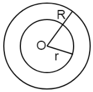
Let two coaxial concentric coils of radius $r$ and $R$$(R>r)$ be placed in the air.
If current ${{I}_{2}}$ flows through $R$, the magnetic flux gets linked up with secondary coil (coils of radius $r$) & is given by ${{\phi }_{s}}=BA=\left( \frac{{{\mu }_{0}}{{I}_{2}}}{2R} \right)\left( \pi {{r}^{2}} \right)$
$\Rightarrow {{\phi }_{s}}=\frac{{{\mu }_{0}}\pi {{r}^{2}}{{I}_{2}}}{2R}$ .......$(1)$
It is known that, ${{\phi }_{s}}=M{{I}_{2}}$ .......$(2)$
From equations $(1)$and $(2)$
$\Rightarrow M{{I}_{2}}=\frac{{{\mu }_{0}}\pi {{r}^{2}}{{I}_{2}}}{2R}$
$\Rightarrow M=\frac{{{\mu }_{0}}\pi {{r}^{2}}}{2R}$
Therefore, the expression for the mutual inductance between a pair of circular coils of radius $r$ and $R$$(R>r)$ is $M=\frac{{{\mu }_{0}}\pi {{r}^{2}}}{2R}$.
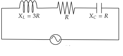
4. Figure shows two electric circuits A and B. Calculate the ratio of power factor of circuit B to the power factor of circuit A.
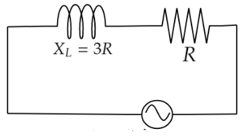
Ans: Power factor of circuit A
$\cos {{\phi }_{A}}=\frac{R}{\sqrt{{{R}^{2}}+X_{L}^{2}}}=\frac{R}{\sqrt{{{R}^{2}}+9{{R}^{2}}}}$
\[\Rightarrow \cos {{\phi }_{A}}=\frac{{R}}{\sqrt{10}{R}}\]
\[\Rightarrow \cos {{\phi }_{A}}=\frac{1}{\sqrt{10}}\] ........$(1)$
Power factor of circuit B
$\cos {{\phi }_{B}}=\frac{R}{\sqrt{{{R}^{2}}+{{\left( {{X}_{L}}-{{X}_{C}} \right)}^{2}}}}=\frac{R}{\sqrt{{{R}^{2}}+{{\left( 3R-R \right)}^{2}}}}$
$\Rightarrow \cos {{\phi }_{B}}=\frac{R}{\sqrt{{{R}^{2}}+4{{R}^{2}}}}=\frac{R}{\sqrt{5{{R}^{2}}}}$
$\Rightarrow \cos {{\phi }_{B}}=\frac{1}{\sqrt{5}}$ ........$(2)$
$\Rightarrow \frac{\left( 2 \right)}{\left( 1 \right)}=\frac{\cos {{\phi }_{B}}}{\cos {{\phi }_{A}}}=\frac{\frac{1}{\sqrt{5}}}{\frac{1}{\sqrt{10}}}$
$\Rightarrow \cos {{\phi }_{B}}:\cos {{\phi }_{A}}=\sqrt{2}$
Therefore, the ratio of power factor of the circuit B to the power factor of the circuit A is $\sqrt{2}$.
5. A horizontal straight wire $10m$ long is extending along east and west and is falling with a speed of $5.0m/s$ at right angles to the horizontal component of the earth’s magnetic field of strength $0.30\times {{10}^{-4}}wb/{{m}^{2}}$.
What is the instantaneous value of the emf induced in the wire?
Ans: It is given that,
Length of the wire, \[l=10m\]
Speed, $\nu =5.0{m}/{s}\;$
${{B}_{H}}=0.30\times {{10}^{-4}}wb/{{m}^{2}}$
Induced emf, $E={{B}_{H}}l\nu $
$\Rightarrow E=0.30\times {{10}^{-4}}\times 10\times 5$
$\Rightarrow E=1.5\times {{10}^{-3}}V$
Therefore, the instantaneous value of the emf induced in the wire is $1.5mV$.
What is the direction of the emf?
Ans: The direction of the induced emf is from west to east.
Which end of the wire is at the higher potential?
Ans: The eastern end of the wire is at higher potential.
6. A circular coil of $N$ turns and radius $r$ is kept normal to a magnetic field, given by $B={{B}_{0}}\cos \omega t$. Deduce an expression for emf induced in the coil. State the rule which helps to detect the direction of induced current.
Ans: It is given that,
$B={{B}_{0}}\cos \omega t$
$E=\frac{-Nd\phi }{dt}$
$\Rightarrow E=\frac{-NA}{dt}d\left( {{B}_{0}}\cos \omega t \right)$
$\Rightarrow E=-NA{{B}_{0}}\left( -sin\omega t \right)\omega $
It is known that, $A=\pi {{r}^{2}}$
$\Rightarrow E=N{{B}_{0}}\pi {{r}^{2}}\omega sin\omega t$
Lenz’s law is used to find the direction of induced emf. It states the direction of induced emf is opposite to the cause producing the induced emf.
7. In exercises 7 and 8 of 2 marks, what is the net power absorbed by each circuit over a complete cycle? Explain your answer.
Ans: From the inductive circuit,
Rms value of current, ${{I}_{rms}}=15.92A$
Rms value of voltage, ${{V}_{rms}}=220V$
It is known that,
Net power absorbed, $P={{V}_{rms}}\times {{I}_{rms}}\cos \phi $
Where,
$\phi $ is the phase difference between voltage and current
For a pure inductive circuit, the phase difference between alternating voltage and current is ${{90}^{0}}$i.e., $\phi ={{90}^{0}}$
$\Rightarrow P=220\times 15.92\cos {{90}^{0}}=0$
Therefore, the net power absorbed is zero.
In a capacitive circuit,
Rms value of current, ${{I}_{rms}}=2.49A$
Rms value of voltage, ${{V}_{rms}}=110V$
It is known that,
Net power absorbed, $P={{V}_{rms}}\times {{I}_{rms}}\cos \phi $
Where,
$\phi $ is the phase difference between voltage and current
For a pure capacitive circuit, the phase difference between alternating voltage and current is ${{90}^{0}}$i.e., $\phi ={{90}^{0}}$
$\Rightarrow P=110\times 2.49\cos {{90}^{0}}=0$
Therefore, the net power absorbed is zero.
8. A series LCR circuit with $R=20\Omega $, $L=1.5H$ and $C=35\mu F$ is connected to a variable frequency $200V$ ac supply. When the frequency of the supply equals the natural frequency of the circuit, what is the average power transferred to the circuit in one complete cycle?
Ans: It is known that,$C=35\mu F=35\times {{10}^{-6}}F$
Resistance, $R=20\Omega $
Inductance, $L=1.5H$
Capacitance,
Voltage, $V=200V$
It is known that,
Impedance,$Z=\sqrt{{{R}^{2}}+{{({{X}_{L}}-{{X}_{C}})}^{2}}}$
At resonance, ${{X}_{L}}={{X}_{C}}$
$\Rightarrow Z=R=20\Omega $
$I=\frac{V}{Z}=\frac{200}{20}$
$\Rightarrow I=10A$
Average power, $P={{I}^{2}}R$
$\Rightarrow P={{10}^{2}}\times 20$
$\Rightarrow P=2000W$
Therefore, the average power transferred is $2000W$.
9. A radio can tune over the frequency range of a portion of $MW$ broadcast band: ($800kHz$ to $1200kHz$). If its LC circuit has an effective inductance of $200\mu H$, what must be the range of its variable capacitor? (Hint: For tuning, the natural frequency i.e., the frequency of free oscillations of the LC circuit should be equal to the frequency of the radio wave.)
Ans: It is given that,
The range of frequency$(f)$ of a radio is $800kHz$ to $1200kHz$.
Effective inductance of the circuit, $L=200\mu H=200\times {{10}^{-6}}H$
It is known that,
Capacitance of variable capacitor for ${{f}_{1}}$ is ${{C}_{1}}=\frac{1}{{{\omega }_{1}}^{2}L}$
Where,
${{\omega }_{1}}$ is the angular frequency for capacitor for ${{f}_{1}}=2\pi {{f}_{1}}$
\[\Rightarrow {{\omega }_{1}}=2\times 3.14\times 800\times {{10}^{3}}rad/s\]
$\Rightarrow {{C}_{1}}=\frac{1}{{{(2\times 3.14\times 800\times {{10}^{3}})}^{2}}\times 200\times {{10}^{-6}}}$
$\Rightarrow {{C}_{1}}=1.9809\times {{10}^{-10}}F$
$\Rightarrow {{C}_{1}}=198.1pF$
${{C}_{2}}=\frac{1}{{{\omega }_{2}}^{2}L}$
$\Rightarrow {{C}_{2}}=\frac{1}{{{(2\times 3.14\times 1200\times {{10}^{3}})}^{2}}\times 200\times {{10}^{-6}}}$
$\Rightarrow {{C}_{2}}=0.8804\times {{10}^{-10}}F$
$\Rightarrow {{C}_{2}}=88.04pF$
Therefore, the range of the variable capacitor is from $88.04pF$ to $198.1pF$.
10. Obtain the resonant frequency and Q-factor of a series LCR circuit with $L=3.0H$ ,$C=27\mu F$ and $R=7.4\Omega $. It is desired to improve the sharpness of the resonance of the circuit by reducing its ‘full width at half maximum’ by a factor of $2$. Suggest a suitable way.
Ans: It is given that,
Inductance, $L=3.0H$
Capacitance, $C=27\mu F=27\times {{10}^{-6}}F$
Resistance,$R=7.4\Omega $
It is known that,
At resonance, angular frequency of the source for the given LCR series circuit is ${{\omega }_{r}}=\frac{1}{\sqrt{LC}}$
$\Rightarrow {{\omega }_{r}}=\frac{1}{\sqrt{3\times 27\times {{10}^{-6}}}}$
$\Rightarrow {{\omega }_{r}}=\frac{{{10}^{3}}}{9}=111.11rad/s$
Therefore, the resonant frequency is $111.11rad/s$.
Q-factor of the series, $Q=\frac{{{\omega }_{r}}L}{R}$
$\Rightarrow Q=\frac{111.11\times 3}{7.4}=45.0446$
Therefore, the Q-factor is $45.0446$.
To improve the sharpness of the resonance by reducing ‘full width at half maximum’ by a factor of $2$without changing ${{\omega }_{r}}$ , reduce the resistance to half.
$\Rightarrow R=\frac{7.4}{2}=3.7\Omega $
Therefore, required resistance is $3.7\Omega $.
5 Marks Questions
1.
Why electric power is generally transmitted over long distances at high a.c. voltage?
Ans: Electric power is generally transmitted over long distances at high a.c. voltage because a small current can flow through the transmission line and reduces the power loss.
An a.c. generator consist of a coil of $50$ turns, area $2.5{{m}^{2}}$ rotating at an angular speed of $60{rad}/{s}\;$ in uniform magnetic field of \[\mathbf{B}=\mathbf{0}.\mathbf{3T}\] between two fixed pole pieces. Given $R=500\Omega $.
Find the maximum current drawn from the generator?
Ans: It is given that,
$n=50$, $A=2.5{{m}^{2}}$,
$\omega =60{rad}/{s}\;$,
$B=0.3 T$ ,
$R=500 \Omega$
${{E}_{0}}=nAB\omega $
$\Rightarrow {{E}_{0}}=50\times 2.5\times 0.3\times 60$
$\Rightarrow {{E}_{0}}=2250V$
${{I}_{0}}=\frac{{{E}_{0}}}{R}=\frac{2250}{500}$
$\Rightarrow {{I}_{0}}=4.5A$
Therefore, the maximum current drawn from the generator is
$4.5A$.
What will be the orientation of the coil with respect to B to have max and zero magnetic flux?
Ans: When the coil is in the vertical position magnetic flux will be maximum and when the coil is in the horizontal position magnetic flux will be zero.
Would the generator work if the coils were stationary and instead the pole pieces rotated together with the same speed?
Ans: The generator will work whenever there is relative motion between the coil and magnet.
2. Explain with the help of a labelled diagram, the principle, construction and working of a transformer.
Ans: Principle: A transformer converts low a.c. voltage to high a.c. voltage or vice – versa. It is based on the principle of mutual induction i.e., emf is induced in a coil when a changing current is produced in the neighbouring coil.
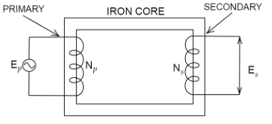
Construction: It consists of two coils wound on a soft iron core. One of the coils called the primary is connected to an a.c. source. The other coil, called the secondary, is connected to the load.
Working: When an alternating emf is applied across the primary coil the input voltage keeps on changing with time due to which magnetic flux through the primary coil changes. This changing magnetic flux gets linked up with the secondary coil also, which in turn produces induced emf in the secondary coil.
${{E}_{s}}={{N}_{s}}\frac{d{{\phi }_{s}}}{dt}$ ........$(1)$
${{E}_{p}}={{N}_{p}}\frac{d{{\phi }_{p}}}{dt}$ ........$(2)$
If all the magnetic flux generated in the primary coil gets linked up with the secondary coil i.e., ${{\phi }_{s}}={{\phi }_{p}}$
Then equations $(1)$ and $(2)$ becomes
$\frac{\left( 1 \right)}{\left( 2 \right)}\Rightarrow \frac{{{E}_{s}}}{{{E}_{p}}}=\frac{{{N}_{s}}}{{{N}_{p}}}$
$\Rightarrow {{E}_{s}}=\frac{{{N}_{s}}}{{{N}_{p}}}{{E}_{p}}$ .........$(3)$
$\frac{{{N}_{s}}}{{{N}_{p}}}=k$ is called transformation ratio
\[k>1\] for step up transformer
$k<1$ for step down transformer
If there is no loss of energy then \[{{E}_{s}}{{I}_{s}}={{E}_{p}}{{I}_{p}}\]
$\Rightarrow \frac{{{E}_{s}}}{{{E}_{p}}}=\frac{{{I}_{p}}}{{{I}_{s}}}$
3. Figure shows a series LCR circuit connected to a variable frequency $230V$ source. $L=5.0H$, $C=80\mu F$, $R=40\Omega $ .
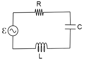
Image source: Self-created
Determine the source frequency which drives the circuit in resonance.
Ans: It is given that,
Voltage, $V=230V$
Inductance, $L=5.0H$
Capacitance, $C=80\mu F=80\times {{10}^{-6}}F$
Resistance, $R=40\Omega $
It is known that,
Source frequency at resonance$=\frac{1}{\sqrt{LC}}$
$\Rightarrow \frac{1}{\sqrt{5\times 80\times {{10}^{-6}}}}=50rad/s$
Therefore, the source frequency of the circuit in resonance is $50rad/s$.
Obtain the impedance of the circuit and the amplitude of current at the resonating frequency.
Ans: It is known that,
At resonance, Impedance,$Z=$ Resistance,$R$
$\Rightarrow Z=R=40\Omega $
$I=\frac{V}{Z}$
$\Rightarrow I=\frac{230}{40}=5.75A$
Amplitude, ${{I}_{0}}=1.414\times I$
$\Rightarrow {{I}_{0}}=1.414\times 5.75$
$\Rightarrow {{I}_{0}}=8.13A$
Therefore, the impedance of the circuit is $40\Omega $ and the amplitude of current at resonating frequency is $8.13A$.
Determine the rms potential drops across the three elements of the circuit. Show that the potential drop across the LC combination is zero at the resonating frequency.
Ans: It is known that,
Potential drop, $V=IR$
Across resistor, ${{V}_{R}}=IR$
$\Rightarrow {{V}_{R}}=5.75\times 40=230V$
Across capacitor, ${{V}_{C}}=I{{X}_{C}}=\frac{I}{\omega C}$
$\Rightarrow {{V}_{C}}=5.75\times \frac{1}{50\times 80\times {{10}^{-6}}}$
$\Rightarrow {{V}_{C}}=1437.5V$
Across Inductor, ${{V}_{L}}=I{{X}_{L}}=I\omega L$
$\Rightarrow {{V}_{L}}=5.75\times 50\times 5$
$\Rightarrow {{V}_{L}}=1437.5V$
Across LC combination, ${{V}_{LC}}=I({{X}_{L}}-{{X}_{C}})$
At resonance, ${{X}_{L}}={{X}_{C}}$
$\Rightarrow {{V}_{LC}}=0$
Therefore, the rms potential drop across Resistor is $230V$, Capacitor is $1437.5V$, Inductor is $1437.5V$ and the potential drop across LC combination is zero at resonating frequency.
4. An LC circuit contains a $20mH$ inductor and a $50\mu F$ capacitor with an initial charge of $10mC$. The resistance of the circuit is negligible. Let the instant the circuit is closed be $t=0$.
What is the total energy stored initially? Is it conserved during LC oscillations?
Ans: It is given that,
Inductance of the inductor, $L=20mH=20\times {{10}^{-3}}H$
Capacitance of the capacitor, $C=50\mu F=50\times {{10}^{-6}}F$
Initial charge on the capacitor, $Q=10mC=10\times {{10}^{-3}}C$
It is known that,
Total energy stored initially in the circuit, $E=\frac{1}{2}\frac{{{Q}^{2}}}{C}$
$\Rightarrow E=\frac{{{(10\times {{10}^{-3}})}^{2}}}{2\times 50\times {{10}^{-6}}}=1J$
Therefore, the total energy stored in the LC circuit will be conserved because there is no resistor $(R=0)$ connected in the circuit.
What is the natural frequency of the circuit?
Ans: It is known that,
Natural frequency of the circuit, $\nu =\frac{1}{2\pi \sqrt{LC}}$
$\Rightarrow \nu =\frac{1}{2\pi \sqrt{20\times {{10}^{-3}}\times 50\times {{10}^{-6}}}}$
$\Rightarrow \nu =\frac{{{10}^{3}}}{2\pi }=159.24Hz$
Natural angular frequency, ${{\omega }_{r}}=\frac{1}{\sqrt{LC}}$
$\Rightarrow {{\omega }_{r}}=\frac{1}{\sqrt{20\times {{10}^{-3}}\times 50\times {{10}^{-6}}}}$
$\Rightarrow {{\omega }_{r}}=\frac{1}{\sqrt{{{10}^{-6}}}}={{10}^{3}}rad/s$
Therefore, the natural frequency is $159.24Hz$ and the natural angular frequency is ${{10}^{3}}rad/s$.
At what time is the energy stored $(i)$ completely electrical (i.e., stored in the capacitor)? $(ii)$ completely magnetic (i.e., stored in the inductor)?
Ans:
Completely electrical
It is known that,
Time period for LC oscillations, $T=\frac{1}{\nu }$
$\Rightarrow T=\frac{1}{159.24}=6.28ms$
Total charge on the capacitor at time $t$, $Q'=Q\cos \left( \frac{2\pi }{T}t \right)$
If energy stored is electrical, $Q'=\pm Q$
Therefore, it can be inferred that the energy stored in the capacitor is completely electrical at time, $t=0,\frac{T}{2},T,\frac{3T}{2},..............$ where, $T=6.3ms$.
Completely magnetic
Magnetic energy is maximum, when electrical energy $Q'$ is equal to $0$.
Therefore, it can be inferred that the energy stored is completely magnetic at time, $t=\frac{T}{4},\frac{3T}{4},\frac{5T}{4},...........$ where, $T=6.3ms$.
At what times is the total energy shared equally between the inductor and the capacitor?
Ans: Consider, $Q'$ be the charge on capacitor when total energy is equally shared between the capacitor and the inductor at time $t$.
When total energy is equally shared between the inductor and capacitor, the energy stored in the capacitor$={}^{1}/{}_{2}($maximum energy$)$.
$\Rightarrow \frac{1}{2}\frac{{{\left( Q' \right)}^{2}}}{C}=\frac{1}{2}\left( \frac{1}{2}\frac{{{Q}^{2}}}{C} \right)$
$\Rightarrow \frac{1}{2}\frac{{{\left( Q' \right)}^{2}}}{C}=\frac{1}{4}\frac{{{Q}^{2}}}{C}$
$\Rightarrow Q'=\frac{Q}{\sqrt{2}}$
It is known that, $Q'=Q\cos \frac{2\pi }{T}t$
$\Rightarrow \frac{Q}{\sqrt{2}}=Q\cos \frac{2\pi }{T}t$
$\Rightarrow \cos \frac{2\pi }{T}t=\frac{1}{\sqrt{2}}=\cos (2n+1)\frac{\pi }{4};$ $n=0,1,2,3.....$
$\Rightarrow t=(2n+1)\frac{T}{8}$
Therefore, total energy is equally shared between the inductor and the capacitor at time$t=\frac{T}{8},\frac{3T}{8},\frac{5T}{8}...........$.
If a resistor is inserted in the circuit, how much energy is eventually dissipated as heat?
Ans: If a resistor is included in the circuit, then the total initial energy gets dissipated as heat energy in the circuit. The LC oscillation gets damped due to the resistance.
5. A coil of inductance $0.50H$ and resistance $100\Omega $ is connected to a $240V,50Hz$ ac supply.
What is the maximum current in the coil?
Ans: It is given that,
Inductance of the inductor, $L=0.50H$
Resistance of the resistor, $R=100\Omega $
Potential of the supply voltage, $V=240V$
Frequency of the supply, $\nu =50Hz$
It is known that,
Peak voltage, ${{V}_{0}}=\sqrt{2}V$
$\Rightarrow {{V}_{0}}=\sqrt{2}\times 240$
$\Rightarrow {{V}_{0}}=339.41V$
Angular frequency of the supply, $\omega =2\pi \nu $
$\Rightarrow \omega =2\pi \times 50=100\pi rad/s$
Maximum current in the circuit, ${{I}_{0}}=\frac{{{V}_{0}}}{\sqrt{{{R}^{2}}+{{\omega }^{2}}{{L}^{2}}}}$
$\Rightarrow {{I}_{0}}=\frac{339.41}{\sqrt{{{(100)}^{2}}+{{(100\pi )}^{2}}{{(0.50)}^{2}}}}=1.82A$
Therefore, the maximum current in the coil is $1.82A$.
What is the time lag between the voltage maximum and the current maximum?
Ans: It is known that,
Equation for voltage, $V={{V}_{0}}\cos \omega t$
Equation for current, $I={{I}_{0}}\cos (\omega t-\phi )$
Where,
$\phi $ is the phase difference between voltage and current.
At time $t=0$, $V={{V}_{0}}$ (voltage is maximum)
If $\omega t-\phi =0$ i.e., at $t=\frac{\phi }{\omega }$ , $I={{I}_{0}}$ (current is maximum)
Therefore, the time lag between maximum voltage and maximum current is $\frac{\phi }{\omega }$ .
$\Rightarrow \tan \phi =\frac{\omega L}{R}$
$\Rightarrow \tan \phi =\frac{2\pi \times 50\times 0.5}{100}=1.57$
$\Rightarrow \phi ={{\tan }^{-1}}(1.57)$
$\Rightarrow \phi ={{57.5}^{\circ }}=\frac{57.5\pi }{180}rad$
Time lag, $t=\frac{\phi }{\omega }$
$\Rightarrow t=\frac{57.5\pi }{180\times 2\pi \times 50}$
$\Rightarrow t=3.19\times {{10}^{-3}}s$
$\Rightarrow t=3.2ms$
Therefore, the time lag between the maximum voltage and maximum current is $3.2ms$.
6. Obtain the answers $(a)$ to $(b)$ in Exercise 5 if the circuit is connected to a high frequency supply $(240V,10kHz)$. Hence, explain the statement that at very high frequency, an inductor in a circuit nearly amounts to an open circuit. How does an inductor behave in a dc circuit after the steady state?
Ans: It is given that,
Inductance of the inductor, $L=0.5H$
Resistance of the resistor, $R=100\Omega $
Potential of the supply voltage, $V=240V$
Frequency of the supply, $\nu =10kHz={{10}^{4}}Hz$
Angular frequency, $\omega =2\pi \nu =2\pi \times {{10}^{4}}rad/s$
Peak Voltage, ${{V}_{0}}=V\sqrt{2}=110\sqrt{2}V$
Maximum current, ${{I}_{0}}=\frac{{{V}_{0}}}{\sqrt{{{R}^{2}}+{{\omega }^{2}}{{C}^{2}}}}$
$\Rightarrow {{I}_{0}}=\frac{240\sqrt{2}}{\sqrt{{{(100)}^{2}}+{{(2\pi \times {{10}^{4}})}^{2}}\times {{(0.5)}^{2}}}}=1.1\times {{10}^{-2}}A$
Therefore, the maximum current in the coil is $1.1\times {{10}^{-2}}A$.
The time lag between maximum voltage and maximum current is $\frac{\phi }{\omega }$ .
For phase difference $\phi $:$\tan \phi =\frac{\omega L}{R}$
$\Rightarrow \tan \phi =\frac{2\pi \times {{10}^{4}}\times 0.5}{100}=100\pi $
$\Rightarrow \phi ={{\tan }^{-1}}(100\pi )$
$\Rightarrow \phi ={{89.82}^{\circ }}=\frac{89.82\pi }{180}rad$
Time lag, $t=\frac{\phi }{\omega }$
$\Rightarrow t=\frac{89.82\pi }{180\times 2\pi \times {{10}^{4}}}$
$\Rightarrow t=25\times {{10}^{-6}}s$
$\Rightarrow t=25\mu s$
Therefore, the time lag between the maximum voltage and maximum current is $25\mu s$.
It can be observed that ${{I}_{0}}$ is very small in this case.
Thus, at high frequencies, the inductor amounts to an open circuit.
In a dc circuit, after a steady state is achieved, $\omega =0$. Thus, inductor $L$ behaves like a pure conducting object.
7. A $100\mu F$ capacitor in series with a $40\Omega $ resistance is connected to a $110V,60Hz$ supply.
What is the maximum current in the circuit?
Ans: It is given that,
Capacitance of the capacitor, $C=100\mu F=100\times {{10}^{-6}}F$
Resistance of the resistor, $R=40\Omega $
Supply voltage, $V=110V$
Frequency oscillations, $\nu =60Hz$
Angular frequency, $\omega =2\pi \nu =2\pi \times 60rad/s$
It is known that,
For a RC circuit, Impedance: $Z=\sqrt{{{R}^{2}}+\frac{1}{{{\omega }^{2}}{{C}^{2}}}}$
Peak Voltage, ${{V}_{0}}=V\sqrt{2}=110\sqrt{2}V$
Maximum current; ${{I}_{0}}=\frac{{{V}_{0}}}{Z}$
$\Rightarrow {{I}_{0}}=\frac{{{V}_{0}}}{\sqrt{{{R}^{2}}+\frac{1}{{{\omega }^{2}}{{C}^{2}}}}}$
$\Rightarrow {{I}_{0}}=\frac{110\sqrt{2}}{\sqrt{{{(40)}^{2}}+\frac{1}{{{(120\pi )}^{2}}{{({{10}^{-4}})}^{2}}}}}$
\[\Rightarrow {{I}_{0}}=\frac{110\sqrt{2}}{\sqrt{1600+\frac{1}{{{(120\pi )}^{2}}{{({{10}^{-4}})}^{2}}}}}=3.24A\]
Therefore, the maximum current in the circuit is $3.24A$.
What is the time lag between the current maximum and the voltage maximum?
Ans: It is known that,
In a capacitor circuit, the voltage lags behind the current by a phase angle of $\phi $.
$\tan \phi =\frac{\frac{1}{\omega C}}{R}=\frac{1}{\omega CR}$
$\Rightarrow \tan \phi =\frac{1}{120\pi \times {{10}^{-4}}\times 40}=0.6635$
$\Rightarrow \phi ={{\tan }^{-1}}(0.6635)$
$\Rightarrow \phi ={{33.56}^{\circ }}=\frac{33.56\pi }{180}rad$
It is known that,
Time lag, $t=\frac{\phi }{\omega }$
$\Rightarrow t=\frac{33.56\pi }{180\times 120\pi }$
$\Rightarrow t=1.55\times {{10}^{-3}}s$
$\Rightarrow t=1.55ms$
Therefore, the time lag between maximum current and maximum voltage is $1.55ms$.
8. Obtain the answers to $(a)$ and $(b)$ in Exercise 7 if the circuit is connected to a \[\mathbf{110V},\mathbf{12kHz}\] supply? Hence, explain the statement that a capacitor is a conductor at very high frequencies. Compare this behaviour with that of a capacitor in a dc circuit after the steady state.
Ans: It is given that,
Capacitance of the capacitor, $C=100\mu F=100\times {{10}^{-6}}F$
Resistance of the resistor, $R=40\Omega $
Supply voltage, $V=110V$
Frequency oscillations, $\nu =12kHz=12\times {{10}^{3}}Hz$
Angular frequency, $\omega =2\pi \nu =2\pi \times 12\times {{10}^{3}}rad/s=24\pi \times {{10}^{3}}rad/s$
Peak Voltage, ${{V}_{0}}=V\sqrt{2}=110\sqrt{2}V$
It is known that,
For a RC circuit, Impedance: $Z=\sqrt{{{R}^{2}}+\frac{1}{{{\omega }^{2}}{{C}^{2}}}}$
Maximum current; ${{I}_{0}}=\frac{{{V}_{0}}}{Z}$
$\Rightarrow {{I}_{0}}=\frac{{{V}_{0}}}{\sqrt{{{R}^{2}}+\frac{1}{{{\omega }^{2}}{{C}^{2}}}}}$
$\Rightarrow {{I}_{0}}=\frac{110\sqrt{2}}{\sqrt{{{(40)}^{2}}+\frac{1}{{{(24\pi \times {{10}^{3}})}^{2}}{{({{10}^{-4}})}^{2}}}}}$
\[\Rightarrow {{I}_{0}}=\frac{110\sqrt{2}}{\sqrt{1600+{{\left( \frac{10}{24\pi } \right)}^{2}}}}=3.9A\]
Therefore, the maximum current in the circuit is $3.9A$.
It is known that,
In a capacitor circuit, the voltage lags behind the current by a phase angle of $\phi $.
$\tan \phi =\frac{\frac{1}{\omega C}}{R}=\frac{1}{\omega CR}$
$\Rightarrow \tan \phi =\frac{1}{24\pi \times {{10}^{3}}\times {{10}^{-4}}\times 40}=\frac{1}{96\pi }$
$\Rightarrow \phi ={{\tan }^{-1}}(\frac{1}{96\pi })$
$\Rightarrow \phi ={{0.2}^{\circ }}=\frac{0.2\pi }{180}rad$
It is known that,
Time lag, $t=\frac{\phi }{\omega }$
$\Rightarrow t=\frac{0.2\pi }{180\times 24\pi \times {{10}^{3}}}$
$\Rightarrow t=0.04\times {{10}^{-6}}s$
$\Rightarrow t=0.04\mu s$
Therefore, the time lag between maximum current and maximum voltage is $0.04\mu s$.
It can be concluded that $\phi $ tends to become zero at high frequencies. At a high frequency, capacitor $C$ acts as a conductor.
In a dc circuit, after the steady state is achieved, $\omega =0$. Therefore, capacitor $C$ amounts to an open circuit.
9. Keeping the source frequency equal to the resonating frequency of the series LCR circuit, if three elements, L, C and R are arranged in parallel, show that the total current in the parallel LCR circuit is minimum at this frequency. Obtain the current rms value in each branch of the circuit for the elements and source specified in Exercise 11 for this frequency.
Ans: It is given that,
An inductor $(L)$, a capacitor $(C)$ and a resistor $(R)$ is connected in parallel with each other in a circuit where,
Inductance, $L=5.0H$
Capacitance, $C=80\mu F=80\times {{10}^{-6}}F$
Resistance, $R=40\Omega $
Potential of the voltage source, $V=230V$
It is known that,
Impedance $(Z)$ of the given LCR circuit is given as:
$\frac{1}{Z}=\sqrt{\frac{1}{{{R}^{2}}}+{{\left( \frac{1}{\omega L}-\omega C \right)}^{2}}}$
Where,
$\omega $ is the angular frequency
At resonance: $\frac{1}{\omega L}-\omega C=0$
$\Rightarrow \omega =\frac{1}{\sqrt{LC}}$
$\Rightarrow \omega =\frac{1}{\sqrt{5\times 80\times {{10}^{-6}}}}=50rad/s$
Therefore, the magnitude of $Z$ is maximum at $50rad/s$ and the total current is minimum.
Rms current flowing through inductor $L$: ${{I}_{L}}=\frac{V}{\omega L}$
$\Rightarrow {{I}_{L}}=\frac{230}{50\times 5}=0.92A$
Rms current flowing through capacitor $C$: ${{I}_{C}}=\frac{V}{\frac{1}{\omega C}}=\omega CV$
$\Rightarrow {{I}_{C}}=50\times 80\times {{10}^{-6}}\times 230=0.92A$
Rms current flowing through resistor $R$: ${{I}_{R}}=\frac{V}{R}$
$\Rightarrow {{I}_{R}}=\frac{230}{40}=5.75A$
Current rms value in inductor is $0.92A$, in capacitor is $0.92A$ and in resistor is $5.75A$.
10. A circuit containing an $80mH$ inductor and a $60\mu F$ capacitor in series is connected to a \[\mathbf{230V},\mathbf{50Hz}\] supply. The resistance of the circuit is negligible.
Obtain the current amplitude and rms values.
Ans: It is given that,
Inductance, $L=80mH=80\times {{10}^{-3}}H$
Capacitance, $C=60\mu F=60\times {{10}^{-6}}F$
Supply voltage, $V=230V$
Frequency, $\nu =50Hz$
Angular frequency, $\omega =2\pi \nu =100\pi rad/s$
Peak voltage, ${{V}_{0}}=V\sqrt{2}=230\sqrt{2}V$
It is known that,
Maximum current: ${{I}_{0}}=\frac{{{V}_{0}}}{(\omega L-\frac{1}{\omega C})}$
\[\Rightarrow {{I}_{0}}=\frac{230\sqrt{3}}{(100\pi \times 80\times {{10}^{-3}}-\frac{1}{100\pi \times 60\times {{10}^{-6}}})}\]
\[\Rightarrow {{I}_{0}}=\frac{230\sqrt{3}}{(8\pi -\frac{1000}{6\pi })}=-11.63A\]
The negative sign is because $\omega L<\frac{1}{\omega C}$
Amplitude of maximum current, $\left| {{I}_{0}} \right|=11.63A$
$\Rightarrow I=\frac{{{I}_{0}}}{\sqrt{2}}=\frac{-11.63}{\sqrt{2}}$
$\Rightarrow I=-8.22A$, which is the rms value of current.
Obtain the rms values of potential drops across each element.
Ans: It is known that,
Potential difference across the inductor, ${{V}_{L}}=I\times \omega L$
$\Rightarrow {{V}_{L}}=8.22\times 100\pi \times 80\times {{10}^{-3}}$
$\Rightarrow {{V}_{L}}=206.61V$
Potential difference across the capacitor, ${{V}_{C}}=I\times \frac{1}{\omega C}$
$\Rightarrow {{V}_{C}}=8.22\times \frac{1}{100\pi \times 60\times {{10}^{-6}}}$
$\Rightarrow {{V}_{C}}=436.3V$, which is the rms value of potential drop.
What is the average power transferred to the inductor?
Ans: Average power transferred to the inductor is zero as actual voltage leads the current by $\frac{\pi }{2}$.
What is the average power transferred to the capacitor?
Ans: Average power transferred to the capacitor is zero as actual voltage lags the current by $\frac{\pi }{2}$.
What is the total average power absorbed by the circuit? (‘Average’ implies ‘averaged over one cycle’.)
Ans: The total average power absorbed (averaged over one cycle) is zero.
11. Suppose the circuit in Exercise 10 has a resistance of $15\Omega $ . Obtain the average power transferred to each element of the circuit, and the total power absorbed.
Ans: It is given that,
Average power transferred to the resistor \[=788.44W\]
Average power transferred to the capacitor $=0W$
Total power absorbed by the circuit \[=788.44W\]
Inductance of inductor, \[L=80mH=80\times {{10}^{-3}}H\]
Capacitance of capacitor, \[C=60\mu F=60\times {{10}^{-6}}F\]
Resistance of resistor, \[R=15\Omega \]
Potential of voltage supply, \[V=230V\]
Frequency of signal, \[\nu =50Hz\]
Angular frequency of signal, \[\omega =2\pi \nu =2\pi \times \left( 50 \right)=100\pi rad/s\]
It is known that,
Impedance, $Z=\sqrt{{{R}^{2}}+{{\left( \omega L-\frac{1}{\omega C} \right)}^{2}}}$
$\Rightarrow Z=\sqrt{{{(15)}^{2}}+{{\left( 100\pi (80\times {{10}^{-3}})-\frac{1}{\left( 100\pi \times 60\times {{10}^{-6}} \right)} \right)}^{2}}}$
\[\Rightarrow Z=\sqrt{{{(15)}^{2}}+{{\left( 25.12-53.08 \right)}^{2}}}=31.728\Omega \]
Now,
$I=\frac{V}{Z}$
$\Rightarrow I=\frac{230}{31.728}=7.25A$
The elements are connected in series to each other. Therefore, impedance of the circuit is given as current flowing in the circuit,
Average power transferred to resistance is given as: ${{P}_{R}}={{I}^{2}}R$
\[\Rightarrow {{P}_{R}}={{\left( 7.25 \right)}^{2}}\times 15=788.44W\]
Average power transferred to capacitor,${{P}_{C}}=$ Average power transferred to inductor, ${{P}_{L}}=0$
Total power absorbed by the circuit: ${{P}_{T}}={{P}_{R}}+{{P}_{C}}+{{P}_{L}}$
${{P}_{T}}=788.44+0+0=788.44W$
Therefore, the total power absorbed by the circuit is \[788.44W\].
12. A series LCR circuit with \[\mathbf{L}=\mathbf{0}.\mathbf{12H},\mathbf{C}=\mathbf{480nF},\mathbf{R}=\mathbf{23}\text{ }\mathbf{\Omega }\] is connected to a $230V$ variable frequency supply.
What is the source frequency for which current amplitude is maximum? Obtain this maximum value.
Ans: It is given that,
Inductance, $L=0.12H$
Capacitance, $C=480nF=480\times {{10}^{-9}}F$
Resistance, $R=23\Omega $
Supply voltage, $V=230V$
Peak voltage, ${{V}_{0}}=230\times \sqrt{2}=325.22V$
It is known that,
Current flowing in the circuit, ${{I}_{0}}=\frac{{{V}_{0}}}{\sqrt{{{R}^{2}}+{{\left( \omega L-\frac{1}{\omega C} \right)}^{2}}}}$
Where,
${{I}_{0}}$ is maximum at resonance.
At resonance: ${{\omega }_{R}}L-\frac{1}{{{\omega }_{R}}C}=0$
Where,
${{\omega }_{R}}$is the resonance angular frequency
${{\omega }_{R}}=\frac{1}{\sqrt{LC}}$
$\Rightarrow {{\omega }_{R}}=\frac{1}{\sqrt{0.12\times 480\times {{10}^{-9}}}}$
$\Rightarrow {{\omega }_{R}}=4166.67rad/s$
Resonant frequency, ${{\nu }_{R}}=\frac{{{\omega }_{R}}}{2\pi }$
$\Rightarrow {{\nu }_{R}}=\frac{4166.67}{2\times 3.14}=663.48Hz$
Maximum current, ${{\left( {{I}_{0}} \right)}_{Max}}=\frac{{{V}_{0}}}{R}$
$\Rightarrow {{\left( {{I}_{0}} \right)}_{Max}}=\frac{325.22}{23}=14.14A$
What is the source frequency for which average power absorbed by the circuit is maximum? Obtain the value of this maximum power.
Ans: It is known that,
Maximum average power absorbed by the circuit; ${{({{P}_{V}})}_{Max}}=\frac{1}{2}\left( {{I}_{0}} \right)_{Max}^{2}R$
$\Rightarrow {{({{P}_{V}})}_{Max}}=\frac{1}{2}\times {{(14.14)}^{2}}\times 23$
$\Rightarrow {{({{P}_{V}})}_{Max}}=2299.3W$
Therefore, the resonant frequency, ${{\nu }_{R}}=663.48Hz$
For which frequencies of the source is the power transferred to the circuit half the power at resonant frequency? What is the current amplitude at these frequencies?
Ans: It is known that,
The power transferred to the circuit is half the power at resonant frequency.
Frequencies at which power transferred is half, $={{\omega }_{R}}\pm \Delta \omega =2\pi ({{\nu }_{R}}\pm \Delta \nu )$
Where,
$\Delta \omega =\frac{R}{2L}$
$\Rightarrow \Delta \omega =\frac{23}{2\times 0.12}=95.83rad/s$
Therefore, the change in frequency, $\Delta \nu =\frac{1}{2\pi }\Delta \omega $
$\Delta \nu =\frac{95.83}{2\pi }=15.26Hz$
\[{{\nu }_{R}}+\Delta \nu =663.48+15.26=678.74Hz\]
\[{{\nu }_{R}}-\Delta \nu =663.48-15.26=648.22Hz\]
Therefore, at $648.22Hz$ and $678.74Hz$ frequencies, the power transferred is half.
At these frequencies, current amplitude:$I'=\frac{1}{\sqrt{2}}\times {{\left( {{I}_{0}} \right)}_{Max}}$
$\Rightarrow I'=\frac{14.14}{\sqrt{2}}=10A$
Therefore, the current amplitude is $10A$.
What is the Q-factor of the given circuit?
Ans: It is known that,
Q-factor of the given circuit, $Q=\frac{{{\omega }_{r}}L}{R}$
$\Rightarrow Q=\frac{4166.67\times 0.12}{23}=21.74$
Therefore, the Q-factor of the given circuit is $21.74$.
13. Answer the following questions:
In any ac circuit, is the applied instantaneous voltage equal to the algebraic sum of the instantaneous voltages across the series elements of the circuit? Is the same true for rms voltage?
Ans: Yes, in any ac circuit, the applied instantaneous voltage is equal to the algebraic sum of the instantaneous voltages across the series elements of the circuit.
The same is not true for rms voltage because voltages across different elements may not be in phase.
A capacitor is used in the primary circuit of an induction coil.
Ans: Yes, a capacitor is used in the primary circuit of an induction coil.
This is because, when the circuit is broken, a high induced voltage is used to charge the capacitor to avoid sparks.
An applied voltage signal consists of a superposition of a dc voltage and an ac voltage of high frequency. The circuit consists of an inductor and a capacitor in series. Show that the dc signal will appear across C and the ac signal across L.
Ans: The dc signal will appear across capacitor $C$ because for dc signals, the impedance of an inductor $L$ is negligible while the impedance of a capacitor $C$ is very high (almost infinite).
Therefore, a dc signal appears across$C$.
For an ac signal of high frequency, the impedance of $L$is high and that of $C$ is very low.
Thus, an ac signal of high frequency appears across $L$.
A choke coil in series with a lamp is connected to a dc line. The lamp is seen to shine brightly. Insertion of an iron core in the choke causes no change in the lamp’s brightness. Predict the corresponding observations if the connection is to an ac line.
Ans: When an iron core is inserted in the choke coil (which is in series with a lamp connected to an ac line), the lamp will glow dimly.
This is because the choke coil and the iron core increase the impedance of the circuit.
Why is choke coil needed in the use of fluorescent tubes with ac mains? Why can we not use an ordinary resistor instead of the choke coil?
Ans: As the choke coil reduces the voltage across the tube without wasting much power, it is used in the fluorescent tubes with ac mains. An ordinary resistor cannot be used instead of choke coil because it wastes power in the form of heat.
14. A small town with a demand of $800kW$ of electric power at $220V$ is situated $15km$ away from an electric plant generating power at $440V$ . The resistance of the two-wire line carrying power is $0.5\Omega perkm$. The town gets power from the line through a $400-220V$ step-down transformer at a sub-station in the town.
Estimate the line power loss in the form of heat.
Ans: It is given that,
Total electric power required, \[\mathbf{P}=\mathbf{800kW}=\mathbf{800}\times \mathbf{1}{{\mathbf{0}}^{3}}\mathbf{W}\]
Supply voltage, \[\mathbf{V}=\mathbf{220V}\]
Voltage at which electric plant is generating power, $V'=440V$
Distance between the town and power generating station, $d=15km$
Resistance of the two wire lines carrying power$=0.5\Omega /km$
Total resistance of the wires, \[\mathbf{R}=\left( \mathbf{15}+\mathbf{15} \right)\mathbf{0}.\mathbf{5}=\mathbf{15}\text{ }\mathbf{\Omega }\]
A step-down transformer of rating \[\mathbf{4000}-\mathbf{220V}\] is used in the sub-station.
Input voltage, ${{V}_{1}}=4000V$
Output voltage, ${{V}_{2}}=220V$
It is known that,
Rms current in the wire lines: $I=\frac{P}{{{V}_{1}}}$
$\Rightarrow I=\frac{800\times {{10}^{3}}}{4000}=200A$
Line power loss$={{I}^{2}}R$
$\Rightarrow {{(200)}^{2}}\times 15$
$\Rightarrow 600\times {{10}^{3}}W=600kW$
Therefore, the line power loss is $600kW$.
How much power must the plant supply, assuming there is negligible power loss due to leakage?
Ans: Assuming that there is negligible power loss due to leakage of the current:
Total power supplied by the plant$=800kW+600kW=1400kW$
Therefore, the plant must supply $1400kW$ of power.
Characterise the step up transformer at the plant.
Ans: It is known that,
Voltage drop in the power line$=IR$
$\Rightarrow V=200\times 15=3000V$
Total voltage transmitted from the plant$=3000+4000=7000V$
The power generated is $440V$.
Therefore, the rating of the step-up transformer situated at the power plant is $440V-7000V$.
15. Do the same exercise as above with the replacement of the earlier transformer by a $40,000-220V$ step-down transformer (Neglect, as before, leakage losses though this may not be a good assumption any longer because of the very high voltage transmission involved). Hence, explain why high voltage transmission is preferred?
Ans: It is given that,
Total electric power required, \[\mathbf{P}=\mathbf{800kW}=\mathbf{800}\times \mathbf{1}{{\mathbf{0}}^{3}}\mathbf{W}\]
Supply voltage, \[\mathbf{V}=\mathbf{220V}\]
Voltage at which electric plant is generating power, $V'=440V$
Distance between the town and power generating station, $d=15km$
Resistance of the two wire lines carrying power$=0.5\Omega /km$
Total resistance of the wires, \[\mathbf{R}=\left( \mathbf{15}+\mathbf{15} \right)\mathbf{0}.\mathbf{5}=\mathbf{15}\text{ }\mathbf{\Omega }\]
The rating of a step-down transformer is \[40000V-220V\].
Input voltage, ${{V}_{1}}=40000V$
Output voltage, ${{V}_{2}}=220V$
It is known that,
Rms current in the wire lines: $I=\frac{P}{{{V}_{1}}}$
$\Rightarrow I=\frac{800\times {{10}^{3}}}{40000}=20A$
Line power loss$={{I}^{2}}R$
$\Rightarrow {{(20)}^{2}}\times 15$
$\Rightarrow 6\times {{10}^{3}}W=6kW$
Therefore, the line power loss is $6kW$.
Assume that there is negligible power loss due to leakage of the current:
Total power supplied by the plant$=800kW+6kW=806kW$
Therefore, the plant must supply $806kW$ of power.
It is known that,
Voltage drop in the power line$=IR$
$\Rightarrow V=20\times 15=300V$
Total voltage transmitted from the plant$=300+40000=40300V$
The power generated in the plant is generated at $440V$.
Therefore, the rating of the step-up transformer situated at the power plant is $440V-40300V$.
Power loss during transmission$=\frac{600}{1400}\times 100=42.8%$
In previous exercise the power loss due to the same reason is $=\frac{6}{806}\times 100=0.744%$
As the power loss is less for a high voltage transmission, high voltage transmissions are preferred for this purpose.
Important Formulas from Class 12 Physics Chapter 7 Alternating Current
Instantaneous Voltage: $V=V0sin(ωt)V = V_0 \sin(\omega t)V=V0sin(ωt)$
RMS Value of Current: $Irms=I02I_{rms} = \frac{I_0}{\sqrt{2}}Irms=2I0$
RMS Value of Voltage: $Vrms=V02V_{rms} = \frac{V_0}{\sqrt{2}}Vrms=2V0$
Impedance of AC Circuit: $Z=R2+(XL−XC)2Z = \sqrt{R^2 + (X_L - X_C)^2}Z=R2+(XL−XC)2$
Reactance: $XL=ωLX_L = \omega LXL=ωL (Inductive Reactance), XC=1ωCX_C = \frac{1}{\omega C}XC=ωC1 (Capacitive Reactance)$
Power in AC Circuit: $P=VrmsIrmscosϕP = V_{rms} I_{rms} \cos\phiP=VrmsIrmscosϕ$
Resonance Frequency: $f0=12πLCf_0 = \frac{1}{2\pi\sqrt{LC}}f0=2πLC1$
Quality Factor: $Q=ω0LRQ = \frac{\omega_0 L}{R}Q=Rω0L$
Phase Angle: $tanϕ=XL−XCR\tan\phi = \frac{X_L - X_C}{R}tanϕ=RXL−XC$
Benefits of Class 12 Physics Chapter 7 Alternating Current
Provides a thorough understanding of electrical circuits in real-life applications like household wiring and power grids.
Builds a foundation for advanced topics like electromagnetism, electronics, and communication systems.
Strengthens problem-solving skills for competitive exams.
It helps to understand the workings of essential devices like transformers, oscillators, and AC generators.
Offers insights into renewable energy systems like wind turbines and solar inverters.
Tips to Study Class 12 Physics Chapter 7 Alternating Current Important Questions
Memorise all formulas and their derivations to solve numerical effectively.
Understand graphical representations like phasor diagrams to visualize concepts better.
Focus on the differences between AC and DC circuits for conceptual clarity.
Solve NCERT textbook problems and previous years’ board exam questions.
Practice numerical problems related to impedance, power factor, and resonance circuits.
Revise key topics like LCR circuits and resonance regularly.
Use online simulations to understand the behavior of AC circuits in real time.
Related Study Materials for CBSE Class 12 Physics Chapter 7
Conclusion
Alternating Current is a vital chapter that bridges theoretical knowledge with practical applications. Mastering its concepts not only boosts board exam scores but also builds a foundation for advanced studies. Utilise the FREE PDF of important questions, revise regularly, and practice diligently to crack your exams.
Download CBSE Class 12 Physics Important Questions 2026-27 PDF
Additional Study Materials for Class 12 Physics

FAQs on Important Questions For Class 12 Physics Chapter 7 Alternating Current - 2026-27
1. What is the typical weightage of questions from Alternating Current in the Class 12 Physics board exam, and what topics are most important?
Chapter 7, Alternating Current, is a high-weightage chapter. You can expect a mix of questions, including:
- 1-Mark: MCQs or short definitions on terms like power factor, RMS value, or resonant frequency.
- 2-Mark: Simple numericals on calculating impedance, reactance, or the Q-factor.
- 3-Mark: Derivations for expressions in LCR circuits or the working of an AC generator.
- 5-Mark: Detailed questions on the principle, construction, and working of a transformer, or a comprehensive numerical problem on a series LCR circuit covering impedance, resonance, and power calculations.
2. What is the difference between the RMS value and the peak value of an alternating current, and why is the RMS value more commonly used?
The peak value (I₀) is the maximum amplitude or highest point of the alternating current waveform. The RMS (Root Mean Square) value (I_rms) is the effective value of the AC. It is defined as the equivalent DC value that would produce the same amount of heat in the same resistor. The RMS value is more practical and commonly used because it helps in calculating the average power consumed by an AC circuit, and most AC measuring instruments are calibrated to read RMS values.
3. What is resonance in a series LCR circuit and how does it impact impedance and current?
Resonance in a series LCR circuit is a condition where the circuit allows maximum current to flow. This occurs at a specific frequency, called the resonant frequency (ωᵣ), where the inductive reactance (Xₗ) becomes equal to the capacitive reactance (Xₑ).
- At resonance, the net reactance (Xₗ - Xₑ) is zero.
- The total impedance (Z) of the circuit becomes minimum and is equal to the resistance (R).
- The current amplitude in the circuit reaches its maximum value (I = V/R), and the voltage and current are in the same phase.
4. Explain the working principle of a transformer. Why can't it be used to change DC voltage?
A transformer works on the principle of mutual induction. When an alternating voltage is applied to the primary coil, it generates a continuously changing magnetic flux. This changing flux links with the secondary coil and induces an alternating EMF (voltage) in it. A transformer cannot be used with DC voltage because a DC source provides a constant current, which creates a steady magnetic flux. With no change in magnetic flux, no EMF is induced in the secondary coil, and the transformer will not function.
5. What does the power factor in an AC circuit signify, and what are its values for purely resistive, inductive, and capacitive circuits?
The power factor (cos φ) represents the ratio of the true power (power actually consumed) to the apparent power (total power supplied) in an AC circuit. It indicates how effectively the electrical power is being converted into useful work.
- For a purely resistive circuit, voltage and current are in phase (φ=0°), so the power factor is 1 (maximum).
- For a purely inductive or purely capacitive circuit, the phase difference is 90° (φ=90°), so the power factor is 0. This means no power is consumed by the circuit.
6. Why is a choke coil considered a better device than a resistor for controlling current in an AC circuit?
A choke coil is essentially an inductor with high inductance and very low resistance. It controls AC current by offering high inductive reactance (Xₗ = ωL). Unlike a resistor, which dissipates a large amount of energy as heat (P = I²R), a choke coil consumes negligible power because its opposition is reactive, not resistive. Therefore, a choke coil reduces current far more efficiently without significant power loss, making it superior to a resistor for AC applications.
7. How is energy conserved during LC oscillations? Describe the transformation of energy between the components.
In an ideal LC circuit with zero resistance, the total energy is conserved and oscillates between the capacitor and the inductor. The process is as follows:
- Initially, the capacitor is fully charged, and all the energy is stored as electrical energy in its electric field.
- As the capacitor discharges, current flows through the inductor, and the electrical energy is converted into magnetic energy stored in the inductor's magnetic field.
- When the capacitor is fully discharged, the current is maximum, and all energy is magnetic.
- The inductor's collapsing magnetic field then recharges the capacitor in the opposite polarity, converting magnetic energy back to electrical energy. This cycle repeats, conserving the total energy.
8. What is the Quality Factor (Q-factor) of a series LCR circuit and what does it indicate about the resonance?
The Quality Factor (Q-factor) of a series LCR circuit is a dimensionless parameter that describes the sharpness of the resonance peak. It is defined as the ratio of the voltage drop across the inductor (or capacitor) to the applied voltage at resonance. A high Q-factor indicates a very sharp and narrow resonance curve, meaning the circuit is highly selective to frequencies near its resonant frequency. A low Q-factor results in a broad and flat resonance curve, making the circuit less selective.
9. From an exam perspective, what is the best approach to solving numerical problems on series LCR circuits?
To solve LCR circuit numericals effectively for the CBSE 2026-27 exam, follow these steps:
- Step 1: List all given values: R, L, C, V, and angular frequency (ω) or frequency (f).
- Step 2: Calculate the inductive reactance (Xₗ = ωL) and capacitive reactance (Xₑ = 1/ωC).
- Step 3: Determine the total impedance (Z) using the formula Z = √[R² + (Xₗ - Xₑ)²].
- Step 4: Calculate the RMS or peak current using I = V/Z.
- Step 5: Find the phase angle (φ) using tan φ = (Xₗ - Xₑ)/R to determine if the circuit is inductive (leading) or capacitive (lagging).
10. Explain why electrical power is transmitted over long distances at very high voltages.
Power is transmitted at high voltages to minimize power loss during transmission. The power loss in transmission lines is primarily due to the heating effect of current, given by the formula P_loss = I²R, where I is the current and R is the resistance of the wires. Since electrical power (P = VI) is constant, by using a step-up transformer to increase the voltage (V) to a very high level, the current (I) is reduced significantly. A lower current leads to a much smaller power loss (since loss is proportional to I²), making the long-distance transmission highly efficient.