


NCERT Exemplar for Class 12 Physics - Current Electricity - Free PDF Download
Exercise
3.1 Consider a current-carrying wire (current I) in the shape of a circle. Note that as the current progresses along the wire, the direction of J (current density) changes in an exact manner, while the current I remain unaffected. The agent that is essentially responsible for is
(a) source of emf.
(b) electric field produced by charges accumulated on the surface of wire.
(c) the charges just behind a given segment of wire which push them just the right way by repulsion.
(d) the charges ahead.
Ans: (b)
Current density (J) depends on the conductivity of a material and the electric field.
Where conductivity is the inverse of resistivity $\sigma = \dfrac{1}{\rho } = \dfrac{l}{{R.A}}$
Where $R$ is the resistance, $A$ is area of cross-section of the wire and $l$ is the total length of the wire.
And the relation between electric field of a medium and current density is given by $\overrightarrow J = \sigma .\overrightarrow E $ v ….(where $\overrightarrow E $ is the electric field of a medium)
Since conductivity is the property of a material it cannot be varied. Where as electric field can be varied by the charges accumulated on the wire surface.
3.2 Two batteries of emf ${\varepsilon _1}$ and ${\varepsilon _2}$ (${\varepsilon _2}$ > ${\varepsilon _1}$) and internal resistances \[{r_1}\]and \[{r_2}\] respectively are connected in parallel as shown in Fig 3.1.
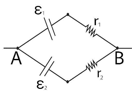
Fig 3.1
(a) The equivalent emf of the two cells is between ${\varepsilon _1}$ and ${\varepsilon _2}$, i.e. ${\varepsilon _1} < {\varepsilon _{eq}} < {\varepsilon _2}$.
(b) The equivalent emf is smaller than ${\varepsilon _1}$.
(c) The equivalent emf is given by ${\varepsilon _{eq}} = {\varepsilon _1} + {\varepsilon _2}$always.
(d) ${\varepsilon _{eq}}$is independent of internal resistances \[{r_1}\]and \[{r_2}\].
Ans: (a)
In the given circuit we can see that a parallel connection is formed between the point A and B.
Thus, we can determine the equivalent potential by the formula given below:
${\varepsilon _{eq}} = \dfrac{{{\varepsilon _1}{r_1} + {\varepsilon _2}{r_2}}}{{{r_1} + {r_2}}}$
Thus, the equivalent emf is not equal to ${\varepsilon _{eq}} = {\varepsilon _1} + {\varepsilon _2}$ and ${\varepsilon _{eq}}$is dependent of internal resistances \[{r_1}\]and \[{r_2}\].
The above equivalent potential will always greater the ${\varepsilon _1}$ and will lie between ${\varepsilon _1} < {\varepsilon _{eq}} < {\varepsilon _2}$.
3.3 A resistance R is to be measured using a meter bridge. Student chooses the standard resistance S to be 100Ω. He finds the null point at ${l_1} = 2.9cm$. He is told to attempt to improve the accuracy. Which of the following is a useful way?
(a) He should measure ${l_1}$ more accurately.
(b) He should change S to 1000Ω and repeat the experiment.
(c) He should change S to 3Ω and repeat the experiment.
(d) He should give up hope of a more accurate measurement with a meter bridge.
Ans: (c)
Since, the null point length is ${l_1} = 2.9cm$ and R is the unknow resistance then the value of the resistance will be
$R = S\left( {\dfrac{{{l_1}}}{{100 - {l_1}}}} \right)$
$R = 100\Omega \left( {\dfrac{{2.9}}{{100 - 2.9}}} \right) = 100\Omega \times \dfrac{{2.9}}{{97.1}} = 2.98\Omega $
So in order to get a balance point (null point) near to 50 cm (middle) in order to improve the accuracy we should take S=3 Ω, as the ratio of R : S will be:
$\dfrac{R}{S} = \left( {\dfrac{{{l_1}}}{{100 - {l_1}}}} \right) = \dfrac{{2.9}}{{97.1}} = \dfrac{1}{{33.483}}$
implies that S is nearly 33 times (actual = 33.483) to R. In order to make ratio R and S equal to 1 : 1, we must take the resistance value of S=3 Ω , which is verified by the option (c).
3.4 Two cells of emf approximately 5V and 10V are to be accurately compared using a potentiometer of length 400cm.
(a) The battery that runs the potentiometer should have voltage of 8V.
(b) The battery of potentiometer can have a voltage of 15V and R adjusted so that the potential drop across the wire slightly exceeds 10V.
(c) The first portion of 50 cm of wire itself should have a potential drop of 10V.
(d) Potentiometer is usually used for comparing resistances and not voltages.
Ans: (b)
The principal cells' emfs are specified as 5V and 10V. As a result, the potential drop across the potentiometer wire must be slightly higher than the 10 V emf. So, the battery should be 15V, and the potential is reduced will be around 4V which can be done by using a rheostat or resistances to make the potential slightly higher than 10V for accurate comparisons. Thus, the correct option will be (b).
3.5 A metal rod of length 10 cm and a rectangular cross-section of 1cm × $\dfrac{1}{2}$ cm is connected to a battery across opposite faces. The resistance will be
(a) maximum when the battery is connected across 1 cm × $\dfrac{1}{2}$ cm faces.
(b) maximum when the battery is connected across 10 cm × 1 cm faces.
(c) maximum when the battery is connected across 10 cm × $\dfrac{1}{2}$ cm faces.
(d) same irrespective of the three faces.
Ans: (a)
As we know that for a given specific wire the resistance becomes $R = \dfrac{{\rho l}}{A}$
Where $R$ is the resistance, $A$ is area of cross section of the wire and $l$ is the total length of the wire.
Thus, the value of resistance will be maximum when the value of $\dfrac{1}{A}$ is maximum, i.e., the value of area ‘A’ must be minimum, it is minimum when area of cross section is 1cm× $\dfrac{1}{2}$cm. Thus, the correct option is (a).
3.6 Which of the following characteristics of electrons determines the current in a conductor?
(a) Drift velocity alone.
(b) Thermal velocity alone
(c) Both drift velocity and thermal velocity.
(d) Neither drift nor thermal velocity.
Ans: (a)
As we know that the value of current flowing in a wire is given by
\[I = Ane{v_d}\]
So, the value of current is directly proportional to the drift velocity of the electrons present $\left( {I \propto {v_d}} \right)$.
Although amount of current flowing also depends on n, which is the number of free electrons present in the wire which increases on increasing temperature of the wire or material, this increase in temperature makes more collision between electrons and in turn increases resistance or decrease the current flow in the wire.
Thus, the correct option is (a).
MULTIPLE CHOICE QUESTIONS- II
MORE THAN ONE OPTION
3.7 Kirchhoff ’s junction rule is a reflection of
(a) conservation of current density vector.
(b) conservation of charge.
(c) the fact that the momentum with which a charged particle approaches a junction is
unchanged (as a vector) as the charged particle leaves the junction.
(d) the fact that there is no accumulation of charges at a junction.
Ans: (b) and (d)
According to the Kirchhoff’s junction rule, the sum of total current (charge flowing per unit time) flowing into a junction is equal to the sum of total current flowing out of the junction i.e., the algebraic sum of current value in an electric network is zero. It is derived from the law of conservation of charges. Since the sum of the charges entering the junction is equal to the sum of the charges outgoing the junction, there remains no possible way for the accumulation of charges at a junction.
Thus, the correct options are (b) and (d).
3.8 Consider a simple circuit shown in Fig 3.2.

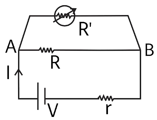
Fig 3.2
(a) Potential drop across AB is nearly constant as R′ is varied.
(b) Current through R′ is nearly a constant as R′ is varied.
(c) Current I depends sensitively on R ′.
(d) $I \leqslant \dfrac{V}{{r + R}}$ always.
Ans: (a) and (d)
As we are given that \[r < < R < < {R_0} < R'\]
And Because R' and R are in parallel, the comparable resistance will always be less than R.
So current value will be $I \leqslant \dfrac{V}{{r + R}}$
And potential across AB will remain nearly constant. It verifies answers (a) and (d).
3.9 Temperature dependence of resistivity ρ(T) of semiconductors, insulators and metals is significantly based on the following factors:
(a) Number of charge carriers can change with temperature T.
(b) Time interval between two successive collisions can depend on T.
(c) Length of material can be a function of T.
(d) Mass of carriers is a function of T.
Ans: (a) and (b)
We know that resistivity (ρ) is affected by charge-carrier mass (m) and relaxation time (τ). Because the mass of a body is constant everywhere, length and mass cannot be functions of Temperature. As a result, response (d) is discarded, and the length of the body changes insignificantly with temperature is also discarded (c).
As Temperature increases, (τ) reduces due to the increased speed of change-carriers, and n increases as temperature increases. As a result, the ρ value will be affected or ρ value is function of T validates responses (a) and (b).
3.10 The measurement of an unknown resistance R is to be carried out using Wheat stones bridge Two students perform an experiment in two ways. The first students takes \[{{\mathbf{R}}_{\mathbf{2}}} = {\mathbf{10\Omega }}\] and \[{{\mathbf{R}}_{\mathbf{1}}} = {\mathbf{5\Omega }}\]. The other student takes \[{{\mathbf{R}}_{\mathbf{2}}} = {\mathbf{1000\Omega }}\] and \[{{\mathbf{R}}_{\mathbf{1}}} = {\mathbf{500\Omega }}\]. In the standard arm, both take \[{{\mathbf{R}}_{\mathbf{3}}} = {\mathbf{5\Omega }}\] . Both find $R = \dfrac{{{R_2}}}{{{R_1}}}{R_3} = 10\Omega $ within errors.
(a) The errors of measurement of the two students are the same.
(b) Errors of measurement do depend on the accuracy with which R2 and R1 can be
measured.
(c) If the student uses large values of R2 and R1, the currents through the arms will be feeble. This will make determination of null point accurately more difficult.
(d) Wheatstone bridge is a very accurate instrument and has no errors of measurement.
Ans: (b) and (c)
Since the $\dfrac{{{R_2}}}{{{R_3}}}$ of and the standard resistance are the identical, the unknown resistance value for both students is 10 ohms. As a result, we may state that the Wheatstone Bridge is the most vulnerable.
The precision of the resistances utilised affects both student's results. As a result, answer (b) is confirmed.
The current via the galvanometer becomes weaker as R1 and R2 value is greater. It will be increasingly difficult to determine the null point with more precision. As a result, answer (c) is confirmed.
3.11 In a meter bridge the point D is a neutral point (Fig 3.3).
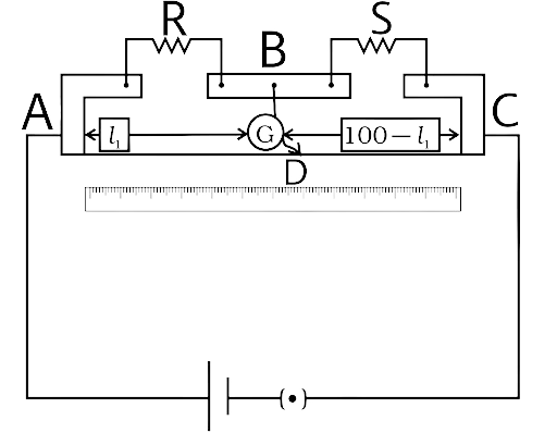
(a) The meter bridge can have no other neutral point for this set of resistances.
(b) When the jockey contacts a point on meter wire left of D, current flows to B from the wire.
(c) When the jockey contacts a point on the meter wire to the right of D, current flows from B to the wire through galvanometer.
(d) When R is increased, the neutral point shifts to left.
Ans: (a) and (c)
The current does not pass through the galvanometer when the jockey is set to D. As a result, the potentials at B and D are the same. Various places on the wire have different potentials.
The fact that point D is unique in order to obtain a null point proves the answer (a).
When the jockey is moved to the right of D on the wire, the potential in the wire decreases, or VB>VD decreases, and current flows from B to D in the wire, verifying the response (c) and discarding the answer (b).
The potential drop across R increases as R is raised. As a result, potential at B rises in order to reach the null point. The jockey must turn right.
VERY SHORT ANSWER TYPE QUESTIONS
3.12 Is the motion of a charge across junction momentum conserving? Why or why not?
Ans:
As we know, drift velocity is dependent on factors like: e, E, τ, and m at a junction point. If the temperature remains constant, e, τ,m remains constant, hence the electron's drift velocity (vd) is solely dependent on the electric field, i.e.
When a free electron approaches a junction, in addition to the uniform electric field (E) in front of it, (vd) is generally constant because E is constant by cell or battery.
Because there is an accumulation of charges on the junction, the drift velocity or momentum will be affected, and momentum will not be conserved at the junction.
3.13 The relaxation time τ is nearly independent of applied E field whereas it changes significantly with temperature T. First fact is (in part) responsible for Ohm’s law whereas the second fact leads to variation of ρ with temperature. Elaborate why?
Ans:
The relaxation time (τ) (average time between successive collisions) decreases as the drift velocity rises, which in turn increases the ρ by formula: $\rho = \dfrac{m}{{n{e^2}\tau }}$.
The drift velocity (vd) changes of the order of one mm on increasing electric field.
Whereas the drift velocity increases of the order of 102m/s when the number of free electrons (n) increases on increasing temperature (T).
As (vd) increases, the relaxation time (τ) in metal or conductor drops significantly.
3.14 What are the advantages of the null-point method in a Wheatstone bridge? What additional measurements would be required to calculate R (unknown) by any other method?
Ans:
The fundamental advantage of the Wheatstone Bridge is that current does not flow in the arm of the galvanometer at the null point, hence there is no effect of galvanometer resistance or consumption of electric energy or potential across the galvanometer. It is a simple and convenient way.
We may use Ohm's law to compute the unknown resistance, which requires us to calculate the least counts and ammeter and voltmeter readings.
Kirchhoff's rules can also be used to the circuit in which unknown resistance is linked to calculate unknown resistance. The procedure is complex because we must measure currents and potential differences across all circuit components.
3.15 What is the advantage of using thick metallic strips to join wires in a potentiometer?
Ans:
Because the cross-sectional area of metallic strips in potentiometers (and metre bridges) is greater than that of a single wire. As a result, the strip's resistance is substantially lower when calculated using the following formula $R = \rho \left( {\dfrac{l}{A}} \right)$:
In a potentiometer, a lengthy resistance wire is wound as indicated in the image.
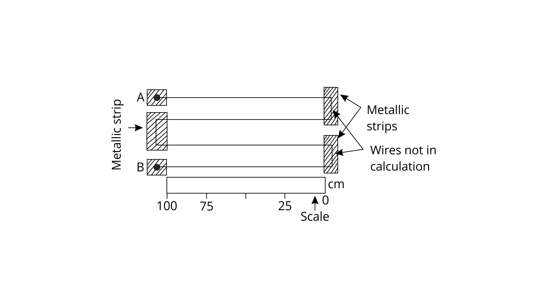
The resistance below the metallic strips is outside of the circuit and computation, making reading and calculations simple.
3.16 For wiring in the home, one uses Cu wires or Al wires. What considerations are involved in this?
Ans:
Metals have low resistance because their resistivities are low. From Ag, Cu, Al, and Fe, the cost of metals used in electric circuits drops (steel). However, because Ag is expensive, Cu or Al wires are utilised in wiring.
3.17 Why are alloys used for making standard resistance coils?
Ans:
Resistance must remain unaffected by changes in temperature, humidity, pressure, and other factors. Alloys have a low temperature coefficient and are unaffected by moisture and other factors.
Alloys have a higher resistivity, which means they require less length to build coils, which reduces the effect of inductance. Standard resistance coils are made of alloys for these reasons.
3.18 Power P is to be delivered to a device via transmission cables having resistance RC. If V is the voltage across R and I the current through it, find the power wasted and how can it be reduced.
Ans:
The reason we know that P = VI, there are two ways to transmit a constant power P across transmission cable:
(i) At low voltage (V) and high current (I), a constant power p is communicated. By \[H = {I^2}R\], high current produces more heat in this approach, and power loss via the cable is greater.
(ii) If a constant or identical amount of power is transmitted at a high voltage (V) and low current. It results in a smaller loss of power due to heat. However, thicker insulation is required during transmission.
To minimize heat losses through towers and thicket (long) insulators, we employ low current and high (132 kV) voltage to deliver high power across long distances.
We can transmit power at low voltages (440V, 220V, 11KV) and larger currents over short distances.
3.19 AB is a potentiometer wire (Fig 3.4). If the value of R is increased, in which direction will the balance point J shift?
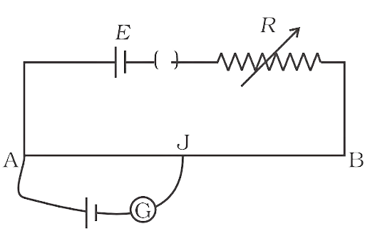
Ans:
As the potential (E) remains constant, if R is increased, the current in the main circuit will decrease (by V= IR). As a result, the potential difference across AB will decrease (by the formula of V=IR). The potential gradient will decrease $\left( {K = \dfrac{V}{{AB}}} \right)$ as R of AB remains constant. To make the potential across AB equal to the potential of the secondary circuit (E'), the length of AJ' must be longer than AJ. As a result, the point J moves closer to B.
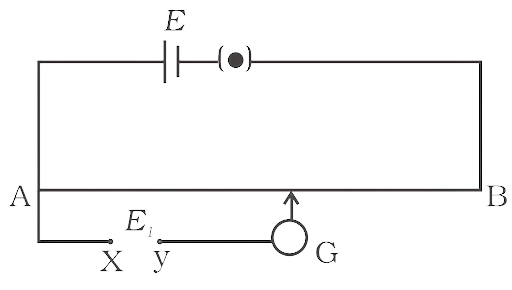
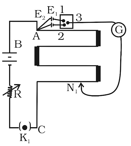
3.20 While doing an experiment with potentiometer (Fig 3.5) it was found that the deflection is one sided and (i) the deflection decreased while moving from one end A of the wire to the end B, (ii) the deflection increased. while the jockey was moved towards the end B.
(i) Which terminal +or –ve of the cell \[{{\mathbf{E}}_{\mathbf{1}}}\] , is connected at X in case (i) and how is \[{{\mathbf{E}}_{\mathbf{1}}}\] related to E?
(ii) Which terminal of the cell \[{{\mathbf{E}}_{\mathbf{1}}}\] is connected at X in case (ii)?
Ans:
(i) Which terminal +or –ve of the cell \[{{\mathbf{E}}_{\mathbf{1}}}\] , is connected at X in case (i) and how is \[{{\mathbf{E}}_{\mathbf{1}}}\] related to E?
When the jockey goes towards B, the one-sided deflection in the galvanometer decreases. As a result, the potential in the galvanometer circuit drops when compared to the earlier potential across AJ or the potential between AJ'. This is achievable when the positive terminal of E1 is at X and the negative terminal is at Y. As a result, E1>E.
(ii) Which terminal of the cell \[{{\mathbf{E}}_{\mathbf{1}}}\] is connected at X in case (ii)?
When the jockey advances from end A to B, the one-sided deflection in the galvanometer increases. As a result, the potential in the galvanometer circuit increases when compared to the earlier potential across AJ or the potential between AJ'. It is conceivable when the positive terminal of E is at Y and the negative terminal is at X. So, E1<E.
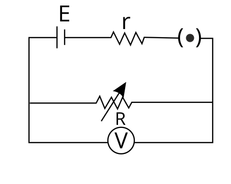
3.21 A cell of emf E and internal resistance r is connected across an external resistance R. Plot a graph showing the variation of P.D. across R, verses R.
Ans:
Since, we have the cell with internal resistance r connected with external resistance R.
The total resistance becomes ${R_s} = R + r$
Current flowing in the circuit $I = \dfrac{E}{{R + r}}$
Now potential across R is $V = IR = \dfrac{{ER}}{{R + r}}$
$V = \dfrac{{ER}}{{R + r}}$
$V = \dfrac{E}{{1 + \dfrac{r}{R}}}$ in this equation we have E and R as constant
The equation of our graph is $V = \dfrac{E}{{1 + \dfrac{r}{R}}}$
Maximum value of potential across R can be E
Thus, the graph becomes:

SHORT ANSWER TYPE QUESTIONS
3.22 First a set of n equal resistors of R each are connected in series to a battery of emf E and internal resistance R. A current (I) is observed to flow. Then the n resistors are connected in parallel to the same battery. It is now observed that the current is increased 10 times. What is ‘n’?
Ans:
Series connection:
Since all the n cells have the internal resistance of R and they all are connected in series with n external resistance of R.
Total resistance becomes ${R_s} = R + nR$
Current in circuit $I = \dfrac{E}{{nR + R}}$
Parallel connection:
Since all the n cells have the internal resistance of R and they all are connected in Parallel with n external resistance of R.
Parallel resistance $\dfrac{1}{{{R_p}}} = \dfrac{n}{R}$
Total resistance becomes ${R_p} = \dfrac{R}{n} + R$
Current in circuit $I = \dfrac{E}{{\dfrac{R}{n} + R}}$
Now current in parallel is 10 times current in series
$\dfrac{E}{{\dfrac{R}{n} + R}} = \dfrac{{10E}}{{nR + R}}$
We get on simplifying $\dfrac{1}{{\dfrac{1}{n} + 1}} = \dfrac{{10}}{{n + 1}}$
$\dfrac{n}{{1 + n}} = \dfrac{{10}}{{n + 1}}$
On cancelling (n + 1) we get n = 10
Thus, n = 10.
3.23 Let there be n resistors \[{{\mathbf{R}}_{\mathbf{1}}}..........{{\mathbf{R}}_{\mathbf{n}}}\] with \[{{\mathbf{R}}_{{\mathbf{max}}}} = {\mathbf{max}}\left( {{{\mathbf{R}}_{\mathbf{1}}}.........{\text{ }}{{\mathbf{R}}_{\mathbf{n}}}} \right)\] and \[{{\mathbf{R}}_{{\mathbf{min}}}} = {\mathbf{min}}\left\{ {{\mathbf{R}}{}_{\mathbf{1}}.....{\text{ }}{{\mathbf{R}}_{\mathbf{n}}}} \right\}\]. Show that when they are connected in parallel, the resultant resistance \[{{\mathbf{R}}_{\mathbf{P}}} < {{\mathbf{R}}_{{\mathbf{min}}}}\] and when they are connected in series, the resultant resistance \[{{\mathbf{R}}_{\mathbf{S}}} > {{\mathbf{R}}_{{\mathbf{max}}}}\]. Interpret the result physically.
Ans:
Let Rmin and Rmax are the minimum and maximum resistances among all resistance given.
Now let check the parallel connection first
\[\dfrac{1}{{{R_P}}} = \dfrac{1}{{{R_1}}} + \dfrac{1}{{{R_2}}} + \dfrac{1}{{{R_3}}}....... + \dfrac{1}{{{R_n}}}\]
Since Rmin is the minimum resistance of all
Now let’s create an inequality.
$\dfrac{1}{{{R_{min}}}} = \dfrac{1}{{{R_{min}}}}$ in this equation we will add the term $\dfrac{1}{{{R_1}}}$ to one of the side to create an inequality
$\dfrac{1}{{{R_{min}}}} < \dfrac{1}{{{R_{min}}}} + \dfrac{1}{{{R_1}}}$
Now, we will add inverse of all the resistances given to us except the inverse of Rmin as it will already be present in the set of resistances given to us
Thus, we get the equation:
$\dfrac{1}{{{R_{min}}}} < \dfrac{1}{{{R_{min}}}} + \left[ {\left( {\dfrac{1}{{{R_1}}} + \dfrac{1}{{{R_2}}} + \dfrac{1}{{{R_3}}}....... + \dfrac{1}{{{R_n}}}} \right) - \dfrac{1}{{{R_{min}}}}} \right]$
Now, we know that \[\dfrac{1}{{{R_1}}} + \dfrac{1}{{{R_2}}} + \dfrac{1}{{{R_3}}}....... + \dfrac{1}{{{R_n}}} = \dfrac{1}{{{R_P}}}\]
So, we get $\dfrac{1}{{{R_{min}}}} < \dfrac{1}{{{R_{min}}}} + \dfrac{1}{{{R_p}}} - \dfrac{1}{{{R_{min}}}}$
$\dfrac{1}{{{R_{min}}}} < \dfrac{1}{{{R_p}}}$
Now we will inverse the inequality. Inversing the inequality changes the sign of the inequality.
So, we get ${R_{\min }} > {R_p}$ hence proved.
Now let’s check series by the same method of inequality
We know that ${R_s} = {R_1} + {R_2} + {R_3} + ........ + {R_n}$
Now let’s create an inequality.
${R_{\max }} = {R_{\max }}$ in this equation we will add the term ${R_1}$ to one of the sides to create an inequality
${R_{\max }} < {R_{\max }} + {R_1}$
Now, we will add inverse of all the resistances given to us except the inverse of Rmax as it will already be present in the set of resistances given to us
Thus, we get the equation:
${R_{\max }} < {R_{\max }} + \left[ {\left( {{R_1} + {R_2} + {R_3} + ........ + {R_n}} \right) - {R_{\max }}} \right]$
Now, we know that ${R_s} = {R_1} + {R_2} + {R_3} + ........ + {R_n}$
So, we get ${R_{\max }} < {R_{\max }} + \left[ {{R_s} - {R_{\max }}} \right]$
${R_{\max }} < {R_s}$
So, we get ${R_{\max }} < {R_s}$ hence proved.
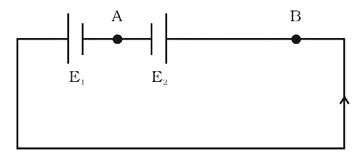
3.24 The circuit in Fig 3.6 shows two cells connected in opposition to each other. Cell E1 is of emf 6V and internal resistance 2Ω; the cell E2 is of emf 4V and internal resistance 8Ω. Find the potential difference between the points A and B.
Ans:
We can draw the above figure as
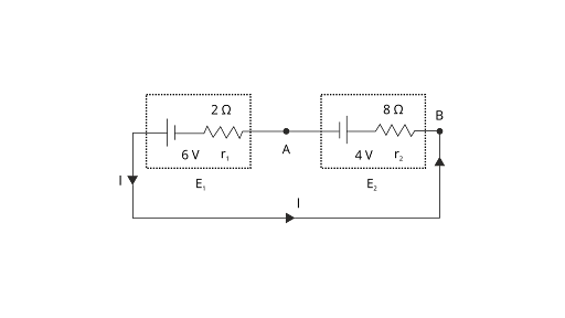
Since E1 is greater than E2 The direction of current in circuit will be as shown in the figure. So, point B is at higher potential than A.
So, VB>VA
Now the current in the circuit is $I = \dfrac{{6 - 4}}{{2 + 8}} = 0.2A$
Now potential difference between A and B is :
${V_B} - I{r_2} - 4 = {V_A}$
${V_B} - {V_V} = 4 + I{r_2}$
Now potential difference between A and B is ${V_B} - {V_V} = 4 + 0.2 \times 8 = 5.6V$
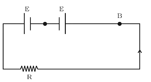
3.25 Two cells of same emf E but internal resistance \[{{\mathbf{r}}_{\mathbf{1}}}\] and \[{{\mathbf{r}}_{\mathbf{2}}}\] are connected in series to an external resistor R (Fig 3.7). What should be the value of R so that the potential difference across the terminals of the first cell becomes zero.
Ans:
Since we have 2 voltage source and three resistance (2 interval cell resistance and 1 external resistance) all of then are connected in series.
So, the value of current becomes $I = \dfrac{{E + E}}{{R + {r_1} + {r_2}}}$
Now we have to make the potential difference across the first cell zero (potential difference between A and B is zero)
${V_1} = E - I{r_1}$
Now we will substitute the value of current and voltage will be zero.
${V_1} = E - {r_1}\left( {\dfrac{{E + E}}{{R + {r_1} + {r_2}}}} \right) = 0$
$E = {r_1}\left( {\dfrac{{E + E}}{{R + {r_1} + {r_2}}}} \right)$
$1 = \dfrac{{2{r_1}}}{{R + {r_1} + {r_2}}}$
$R + {r_1} + {r_2} = 2{r_1}$
${r_1} - {r_2} = R$
The required condition for the potential difference across 1st cell to be zero is ${r_1} - {r_2} = R$
3.26 Two conductors are made of the same material and have the same length. Conductor A is a solid wire of diameter 1mm. Conductor B is a hollow tube of outer diameter 2mm and inner diameter 1mm. Find the ratio of resistance RA to RB.
Ans:
Let’s compare the resistance of wire A and B.
$\dfrac{{{R_A}}}{{{R_B}}} = \dfrac{{{\rho _A}{{\left( {\dfrac{l}{A}} \right)}_A}}}{{{\rho _B}{{\left( {\dfrac{l}{A}} \right)}_B}}}$
Since ρ1 = ρ2 = ρ and l1 = l2 = l
We are left with
$\dfrac{{{R_A}}}{{{R_B}}} = \dfrac{{\dfrac{1}{{{A_A}}}}}{{\dfrac{1}{{{A_B}}}}} = \dfrac{{{A_B}}}{{{A_A}}}$
$\dfrac{{{R_A}}}{{{R_B}}} = \dfrac{{{A_B}}}{{{A_A}}} = \dfrac{{\pi \left[ {{r_2}^2 - {r_1}^2} \right]}}{{\pi {r_1}^2}}$
$\dfrac{{{R_A}}}{{{R_B}}} = \dfrac{{\pi \left[ {{r_2}^2 - {r_1}^2} \right]}}{{\pi {r_1}^2}} = \dfrac{{{{10}^{ - 6}} - 0.25 \times {{10}^{ - 6}}}}{{0.25 \times {{10}^{ - 6}}}} = \dfrac{{0.75 \times {{10}^{ - 6}}}}{{0.25 \times {{10}^{ - 6}}}} = 3$
So, ${R_A}:{R_B} = 3:1$
3.27 Suppose there is a circuit consisting of only resistances and batteries. Suppose one is to double (or increase it to n-times) all voltages and all resistances. Show that currents are unaltered. Do this for circuit of Example 3.7 in the NCERT Text Book for Class XII.
Ans:
Case I:
Consider a circuit that has some batteries \[{E_1},{E_2},{E_3}, \ldots ..\]and these batteries have their internal resistance \[{r_1},{r_2},{r_3}, \ldots \ldots \ldots \]. This entire system of batteries are being connected to an external resistance of \[{R_1},{R_2},{R_3} \ldots \ldots \].
Let the equivalent resistance, emf and internal resistance of above combination is Req, Eeq, and req respectively.
So, the current flowing in the circuit is ${I_1} = \dfrac{{{E_{eq}}}}{{{R_{eq}} + {r_{eq}}}}$
Now the resistance and cells are again connected in a manner that their equivalent
resistance, emf and internal resistance are nReq, nEeq, and nreq respectively.
So, the current flowing in the newly designed circuit is ${I_2} = \dfrac{{n{E_{eq}}}}{{n{R_{eq}} + n{r_{eq}}}}$
On simplifying ${I_2}$we get
${I_2} = \dfrac{{n{E_{eq}}}}{{n{R_{eq}} + n{r_{eq}}}} = \dfrac{{n{E_{eq}}}}{{n\left( {{R_{eq}} + {r_{eq}}} \right)}} = \dfrac{{{E_{eq}}}}{{{R_{eq}} + {r_{eq}}}} = {I_1}$
This proves that the value of the current remains same if the R, E and r of a circuits is increased by n times.
LONG ANSWER TYPE QUESTIONS
3.28 Two cells of voltage 10V and 2V and internal resistances 10Ω and 5Ω respectively, are connected in parallel with the positive end of 10V battery connected to negative pole of 2V battery (Fig 3.8). Find the effective voltage and effective resistance of the combination.
Ans:
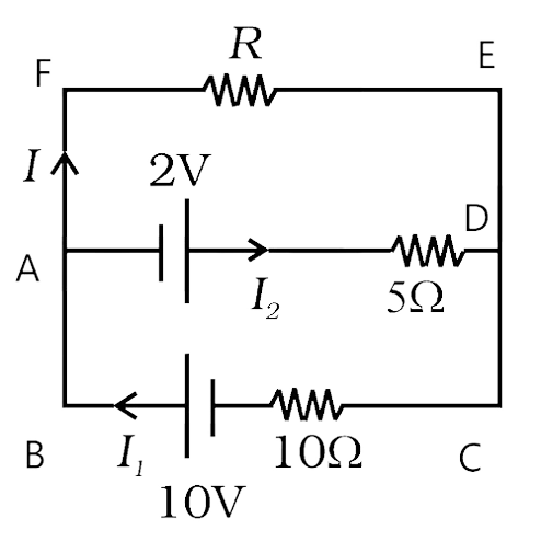
Applying Kirchhoff’s junction rule at point A
${I_1} = I + {I_2}$ …….(1)
Now we will Apply Kirchhoff’s loop rule on loop BCEF
We get $10 = IR + 10{I_1}$ …….(2)
Now we will Apply Kirchhoff’s loop rule on loop ADEF
We get $2 = - IR + 5{I_2}$ …….(3)
Now we will put ${I_2} = {I_1} - I$ from equation (1) in equation (3)
$2 = - IR + 5\left( {{I_1} - I} \right)$
$2 = 5\left( {{I_1} - I} \right) - IR$ …….(4)
Now we will multiply 2 with equation (4) and then we will subtract equation (2) from it
$4 = 10{I_1} - 10I - 2IR$ ……..(5)
$10 = IR + 10{I_1}$ ………(2)
After subtracting (2) from (5) the above two we get:
$6 = 3IR + 10I$
Now
$2 = \dfrac{{3IR + 10I}}{3}$ we divide both divide by 3
$2 = I\left( {R + \dfrac{{10}}{3}} \right)$ ……..(6)
Let the effective potential difference due to both batteries present in the circuit is Veq.
Then it will be across resistance R.
So, ${V_{eq}} = I\left( {R + {R_{eq}}} \right)$ ……..(7)
Where the term Req is the resistance (equivalent) of circuit excluding R.
We can very easily compare equation (6) and (7) to get the value of
${V_{eq}} = 2V$ and ${R_{eq}} = \dfrac{{10}}{3}\Omega $

3.29 A room has AC run for 5 hours a day at a voltage of 220V. The wiring of the room consists of Cu of 1 mm radius and a length of 10 m. Power consumption per day is 10 commercial units. What fraction of it goes in the joule heating in wires? What would happen if the wiring is made of aluminium of the same dimensions?
\[\left[ {{{\mathbf{\rho }}_{{\mathbf{cu}}}} = {\mathbf{1}}.{\mathbf{7}} \times {\mathbf{1}}{{\mathbf{0}}^{--{\mathbf{8}}}}{\mathbf{\Omega m}},{{\mathbf{\rho }}_{{\mathbf{Al}}}} = {\mathbf{2}}.{\mathbf{7}} \times {\mathbf{1}}{{\mathbf{0}}^{--{\mathbf{8}}}}{\mathbf{\Omega m}}} \right]\]
Ans:
Total energy consumed in 5 hrs a day by AC and wiring =10kWh
Energy consumed per hour by the AC and wiring =2 kWh
So total power of the AC and wire system is = 2000 W
Now the voltage is 220 volts and $Power = VI$
So, the current in the system is \[I = \dfrac{P}{V} = \dfrac{{2000}}{{220}} \simeq 9A\]
Let P0 is power of wiring then
${P_0} = {I^2}{R_0}$
Now the value resistance of the wire ${R_0} = \dfrac{{{\rho _0}l}}{A}$
Now the wires are made from copper
Power of the wires ${P_0} = {I^2}\left( {\dfrac{{{\rho _0}l}}{A}} \right)$
${P_0} = {I^2}\left( {\dfrac{{{\rho _0}l}}{A}} \right) = 81 \times \dfrac{{10 \times 1.7 \times {{10}^{ - 8}}}}{{\pi {{\left( {{{10}^{ - 3}}} \right)}^2}}} = \dfrac{{1377 \times {{10}^{ - 2}}}}{\pi } = 4.38W$
So, ${P_0} \simeq 4.4W$
So, the energy loss per sec in the wiring is equal to the power = ${P_0} \simeq 4.4W$
Energy loss $ \simeq 4.4J/\sec $
The fractional of energy loss due to heating of wires $ = \dfrac{{4.4}}{{2000}} \times 100\% = 0.22\% $
Now let’s compare the power loss of aluminium and copper
$\dfrac{{{P_{Al}}}}{{{P_{Cu}}}} = \dfrac{{{I^2}{R_{Al}}}}{{{I^2}{R_{Cu}}}} = \dfrac{{{I^2}{\rho _{Al}}\left( {\dfrac{l}{A}} \right)}}{{{I^2}{\rho _{Cu}}\left( {\dfrac{l}{A}} \right)}}$
Since we will take wires of same dimension so the term of length and are will cancel out, along with the term of current which is common.
$\dfrac{{{P_{Al}}}}{{{P_{Cu}}}} = \dfrac{{{\rho _{Al}}}}{{{\rho _{Cu}}}}$
${P_{Al}} = \dfrac{{2.7 \times {{10}^{ - 8}}}}{{1.7 \times {{10}^{ - 8}}}}{P_{Cu}}$
${P_{Al}} = \dfrac{{2.7 \times {{10}^{ - 8}}}}{{1.7 \times {{10}^{ - 8}}}}4.4 \simeq 7W$
So, power loss in Aluminium wiring =7 Watt
The fractional of energy loss due to Aluminium wiring $ = \dfrac{7}{{2000}} \times 100\% = 0.35\% $
3.30 In an experiment with a potentiometer, VB = 10V. R is adjusted to be 50Ω (Fig. 3.9). A student wanting to measure voltage E1 of a battery (approx. 8V) finds no null point possible. He then diminishes R to 10Ω and is able to locate the null point on the last (4th) segment of the potentiometer. Find the resistance of the potentiometer wire and potential drop per unit length across the wire in the second case.
Ans:
Let the resistance of potentiometer wire be $R'$
The variable resistance is adjusted to \[R = 50\Omega \]
Let ‘I’ be the current in primary circuit which is at EB = 10V
Primary circuit current $I = \dfrac{{{V_B}}}{{R + R'}} = \dfrac{{10}}{{50 + R'}}$ ….(I)
The potential difference across the wire of potentiometer is
$V' = IR'$
Now we will put the value of I to find $V'$
$V' = \dfrac{{10}}{{50 + R'}} \times R'$ ……(II)
As with \[R = 50\Omega \] resistance and the null point cannot be obtained by 8 Volt.
So, V’< 8 Volt.
Since, V’< 8 Volt we get the inequality
$\dfrac{{10}}{{50 + R'}} \times R' < 8$
$10R' < 8\left( {50 + R'} \right)$
$2R' < 400$
$R' < 200$
Similarly, another null point obtained by \[R = 10\Omega \]. Then V”>8 at balance point
So, it is possible when:
\[V'' > 8\]
We will put \[R = 10\Omega \]in $I = \dfrac{{{V_B}}}{{R + R'}}$ and thus, we can obtain V’’
As $V'' = IR'$
So, we get the inequality
$\dfrac{{10}}{{10 + R'}} \times R' > 8$
$10R' > 8\left( {10 + R'} \right)$
$2R' > 80$
$R' > 40$
As the null point is obtained on 4th segment or at 3/4 of total length So at 3/4 R’ (No balance point)
We will replace R’ by 3/4 R’ but the value of \[R = 10\Omega \]will remain unchanges
The inequality we get at balance point
$\dfrac{{10}}{{10 + R'}} \times \left( {\dfrac{3}{4}R'} \right) < 8$
\[7.5R' < 80 + 8R'\]
\[ - 0.5R' < 80\]
\[R' < - 160\]
R’ can never be negative so, -160 Ω is considered 160 Ω.
Thus, we now range the value of R’ is
$160 < R' < 200$
At any R’ between 160 Ω and 200 Ω we will be able to achieve null point. Since the null point is on last 4th segment of potentiometer wire, so the potential drop across 400cm wire is greater enough than 8 Volt.
So, \[k \times 400cm > 8V\] ….(At balance point)
\[k > \dfrac{8}{{400}}V/cm\]
\[k > 2V/m\]
And as balance point is at 4th wire, so no balance point at 3m.
So, \[k \times 300cm < 8V\]
\[k < \dfrac{8}{{300}}V/cm\]
\[k < \dfrac{8}{3}V/m\]
So, the value of k ranges from \[\dfrac{8}{3}V/m > k > 2V/m\]
3.31 (a) Consider circuit in Fig 3.10. How much energy is absorbed by electrons from the initial state of no current (ignore thermal motion) to the state of drift velocity?
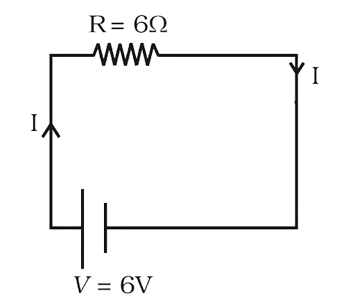
(b) Electrons give up energy at the rate of RI2 per second to the thermal energy. What time scale would one associate with energy in problem (a)?
n = no of electron/volume = 1029/m3,
length of circuit = 10 cm,
cross-section = A = 1mm2
Ans:
Area of the wire = A = 1mm2 $ = 1 \times {10^{ - 6}}{m^2}$
Resistance $R = 6\Omega $
n = no of electron/volume = 1029/m3
Volage = 6 volts
Current in the circuit $ = I = \dfrac{V}{R} = \dfrac{6}{6} = 1A$
Charge of an electron = e = 1.6×10⁻¹⁹ C
Mass of an electron = me = 9.1×10⁻³¹ Kg
Length = 10 cm = 10-1 m
(a) Consider circuit in Fig 3.10. How much energy is absorbed by electrons from the initial state of no current (ignore thermal motion) to the state of drift velocity?
We know that current in terms of drift velocity can be written as
$I = Ane{v_d}$
Noe drift velocity = ${v_d} = \dfrac{I}{{Ane}}$
${v_d} = \dfrac{I}{{Ane}} = \dfrac{1}{{1 \times {{10}^{ - 6}}{m^2} \times 1.6 \times {{10}^{ - 19}}C \times {{10}^{29}}}}m/s$
${v_d} = \dfrac{{{{10}^{ - 4}}}}{{1.6}}m/s$
Kinetic energy carried by one Electron:
$K.E = \dfrac{1}{2} \times m{\left( {{v_d}} \right)^2}$
Number of electrons (free) in wire = n (volume of wire)
Number of electrons (free) in wire = n × A × L
KE of all electrons = $K.E = \dfrac{1}{2} \times m{\left( {{v_d}} \right)^2} \times nAL$
$K.E = \dfrac{1}{2} \times \left( {9.1 \times {{10}^{ - 31}}} \right) \times {\left( {\dfrac{{{{10}^{ - 4}}}}{{1.6}}} \right)^2} \times {10^{29}} \times \left( {1 \times {{10}^{ - 6}}} \right) \times {10^{ - 1}}$
$K.E = {\text{1}}{\text{.78}} \times {10^{ - 17}}J$
So, to start flow of current I, the amount of energy the electrons will take from the cell is:
KE of all electrons $K.E = {\text{1}}{\text{.78}} \times {10^{ - 17}}J$
(b) Electrons give up energy at the rate of RI2 per second to the thermal energy. What time scale would one associate with energy in problem (a)?
Loss of energy during current flowing = I2R (this energy is in form of power; meaning it is the rate of energy loss)
Power $P = {I^2}R = 1 \times 1 \times 6 = 6W$
Now energy is power multiplied with time
$E = Pt$
So, the time scale $t = \dfrac{E}{P}$
$t = \dfrac{E}{P} = \dfrac{{1.78 \times {{10}^{ - 17}}}}{6} = 0.29 \times {10^{ - 17}}\sec $
The approx. time is $ \cong 3 \times {10^{ - 18}}\sec $
A Brief Introduction to Class 12 Chapter 3 - Current Electricity
The chapter Current Electricity Class 12 discusses the rules that govern the nature of electric current. Also, it discusses the contributions of notable scientists such as Kirchhoff and Ohm to Physics. If you have any questions or doubts in this chapter, refer to the NCERT Class 12 chapter 3 PDF. Solving these questions will help you have a better understanding of the material and also be better prepared for the final exam.
Students in Class 12 will learn about circuit diagrams, drawings, energy diagrams, and graphs, as well as real-life examples to make the material more understandable. This chapter further explains that a current is a scalar number, that germanium follows Ohm's law, that Kirchhoff's rule is based on charge conservation, and so on.
After completing their syllabus students must refer to other study material especially the NCERT Exemplar for Class 12 Physics. All the solutions for the questions are available for free download on Vedantu. These can truly help students give their preparation and edge and also help in their preparation for competitive exams.
Why wait then? get the exemplar solutions framed by the top subject matter experts of Vedantu right away. add it to your study schedule and find the answers to the conceptual questions without any hassle. get to know how the experts have approached the questions and formulate a strategy to save time. Use this strategy to answer questions during the board exams and in the competitive exams.


FAQs on NCERT Exemplar for Class 12 Physics Chapter 3 - Current Electricity (Book Solutions)
1. Which topics are there in CBSE Class 12 physics chapter 3?
The Current Electricity Class 12 solutions PDF has a total of 24 questions. This includes numerical, derivation, and subjective type problems. They are based on the chapter's concepts listed below:
Electric Current in a Conductor: Students will learn how electric current flows across conductors in this lesson.
Ohm's Law and Its Applications: Students will learn about Ohm's Law and its different applications in solving numerical issues in this section.
Electron Drift and Resistivity Origin, and Mobility: It gives an overview of the average velocity attained by charged particles, the application of resistivity to diverse issues.
Electrical Energy: Students will learn about the role of charged particles (electrons) in the generation of electricity.
Series and Parallel Resistors: There are answers about series and parallel resistors.
Cells, Internal Resistance, and EMF: Different types of difficulties on this and the solutions are well explained.
Kirchhoff's Rule: This section's questions concern Kirchhoff's Law's treatment of potential difference and current.
Wheatstone Bridge: Numerical based on it will teach how to use a Meter Bridge to determine unknown resistance.
Potentiometer: Students will learn about the potentiometer. Also, they will learn how its three-terminal resistor produces an adjustable voltage.
2. What is the distribution of marks for CBSE Class 12 physics chapter 3?
Current Electricity is the title of the chapter and it contains seven marks in the CBSE 12 board exam. The types of questions can be very short answers, short answers I and II, value-based questions, and long answer questions. There are various topics in the chapter which are important for the exam. Also, there can be a possibility of numerical-based questions. So preparing this chapter is a must. To practice for this chapter, you can solve the exemplar problems in the NCERT textbook.
3. Why are the NCERT Solutions for Class 12 Physics Chapter 3 so important?
NCERT Solutions for Class 12 Physics Chapter 3 "Current Electricity" are important for exams and can often confuse students. Using the solutions will assist you in understanding the concepts and guiding you through the numerical difficulties. They also provide you with a good understanding of the types of questions that will be asked in exams and prepare you to approach them confidently. It is critical to be well-prepared for exams, and NCERT Solutions provide the greatest online assistance for students.
4. How can I prepare effectively for the exams for Class 12 Physics Chapter 3?
Because of the many laws and numerical rules in the chapter, Current Electricity can often be confusing for students. To thoroughly prepare for exams, go through all of the subjects in this chapter. Clear the ideas and solve the problems numerically. Solve the exercises in the books and then double-check them with NCERT Solutions. This will help you to gain a sense of how to respond to questions on the exam. Make notes to make the revision process go more smoothly.
5. Where can I get NCERT Solutions for Class 12 Chapter 3 Physics in PDF format?
The PDF for Physics NCERT Solutions for Class 12: Chapter 3 may be downloaded from Vedantu's website. Vedantu makes all of the study materials available for free. When you go to NCERT Solutions chapter 3 Current and Electricity, you'll be directed to a page with chapter-by-chapter solutions. Select Chapter 3: Current Electricity from the drop-down menu. After that, you'll be able to get the NCERT Solution and additional chapter-related study materials. These solutions might be a student's ideal study companion. This is because they assist in offering the best instruction while also making learning enjoyable.