Courses
Courses for Kids
Free study material
Offline Centres
More
Store Icon
Store

NCERT Solutions for Class 12 Physics Chapter 3 - Current Electricity

ffImage
Last updated date: 17th Apr 2024
Total views: 775.8k
Views today: 18.75k

NCERT Class 12 Physics Chapter 3: Complete Resource for Current Electricity

The Class 12 Physics Chapter 3 NCERT Solutions PDF for Current Electricity is now available for download from Vedantu's official website. These solutions are created by subject matter experts with years of teaching experience, ensuring that all answers related to the chapter are thoroughly and efficiently explained, with proper justifications and solutions provided. In case of any doubts, students can easily visit the website and not only download the CBSE NCERT Solutions for Class 12 Physics Chapter 3 PDF file but can also reach out to the online helping staff who will promptly get in touch to assist with any queries.


Class:

NCERT Solutions for Class 12

Subject:

Class 12 Physics

Chapter Name:

Chapter 3 - Current Electricity

Content-Type:

Text, Videos, Images and PDF Format

Academic Year:

2024-25

Medium:

English and Hindi

Available Materials:

  • Chapter Wise

  • Exercise Wise

Other Materials

  • Important Questions

  • Revision Notes


List of Topics Covered Under NCERT Solutions for Class 12 Physics Chapter 3  Current Electricity

The topics addressed in the chapter Current electricity are listed below. This chapter thoroughly explains how electricity passes through the conductor, the conductor's response to the electricity, what resistivity is, how cells work, what the cell's response will be when connected in series or parallel, how the current flow is calculated, and all other pertinent information.


  • Electric Current

  • Electric Currents in Conductors

  • Ohm’s law

  • Drift of Electrons and the Origin of Resistivity

  • Limitations of Ohm’s Law

  • Resistivity of Various Materials

  • Temperature Dependence of Resistivity

  • Electrical Energy, Power

  • Combination of Resistors — Series and Parallel

  • Cells, emf, Internal Resistance

  • Cells in Series and in Parallel

  • Kirchhoff’s Rules

  • Wheatstone Bridge

  • Meter Bridge

  • Potentiometer

Competitive Exams after 12th Science
More Free Study Material for Current Electricity
icons
Revision notes
695.7k views 12k downloads
icons
Important questions
669.6k views 12k downloads
icons
Ncert books
681.6k views 15k downloads

Current Electricity Chapter at a Glance - Class 12 NCERT Solutions

  • Current through a given area of a conductor is the net charge passing per unit time through the area.

  • Motion of conduction electrons in electric field E is the sum of (i) motion due to random collisions and (ii) that due to E. The motion due to random collisions averages to zero and does not contribute to vd.

  • Current is a scalar although we represent current with an arrow. Currents do not obey the law of vector addition. That current is a scalar also follows from it’s definition. The current I through an area of cross-section is given by the scalar product of two vectors:

I = j. ΔS, where j and ΔS are vectors. 

  • The resistance R of a conductor depends on its length l and cross-sectional area A through the relation,

 $R=\frac{\rho \l }{A}$ 

where ρ, called resistivity is a property of the material and depends on temperature and pressure.

  • Electrical resistivity of substances varies over a very wide range. Metals have low resistivity, in the range of 10–8 Ω m to 10–6 Ω m. Insulators like glass and rubber have 1022 to 1024 times greater resistivity. Semiconductors like Si and Ge lie roughly in the middle range of resistivity on a logarithmic scale.

  • In most substances, the carriers of current are electrons; in some cases, for example, ionic crystals and electrolytic liquids, positive and negative ions carry the electric current.

  • Current density j gives the amount of charge flowing per second per unit area normal to the flow, j = nq vd where n is the number density (number per unit volume) of charge carriers each of charge q, and vd is the drift velocity of the charge carriers. For electrons q = – e. If j is normal to a cross-sectional area A and is constant over the area, the magnitude of the current I through the area is nevd A.

  • Using E = V/l, I = nevd A, and Ohm’s law, one obtains $\frac{eE}{m}=\rho\frac{ne^2}{m}v_d$

The proportionality between the force eE on the electrons in a metal due to the external field E and the drift velocity vd (not acceleration) can be understood, if we assume that the electrons suffer collisions with ions in the metal, which deflect them randomly. If such collisions occur on an average at a time interval τ, 

vd = aτ = eEτ/m

where a is the acceleration of the electron. This gives 

$\rho=\frac{m}{ne^2\tau }$

  • When a source of emf ε is connected to an external resistance R, the voltage Vext across R is given by 

$V_{ext}=IR=\frac{\varepsilon }{R+r}R$

  • (a) Total resistance R of n resistors connected in series is given by R = R1 + R2 +..... + Rn

  (b) Total resistance R of n resistors connected in parallel is given by 

$\frac{1}{R}=\frac{1}{R_1}+\frac{1}{R_2}+.....\frac{1}{R_n}$

  • Kirchhoff’s Rules

(a) Junction Rule: At any junction of circuit elements, the sum of currents entering the junction must equal the sum of currents leaving it. Kirchhoff’s junction rule is based on conservation of charge.

(b) Loop Rule: The algebraic sum of changes in potential around any closed loop must be zero.

  • The Wheatstone bridge is an arrangement of four resistances – R1, R2, R3, R4 as shown in the text. The null-point condition is given by

$\frac{R_1}{R_2}=\frac{R_3}{R_4}$ using which the value of one resistance can be determined, knowing the other three resistances.

  • The measurement of resistance by Wheatstone bridge is not affected by the internal resistance of the cell.

  • If a skeleton cube is made with 12 equal resistance each having resistance R then the net resistance across.

(a) The longest diagonal (EC or AG) $=\frac{5}{6}R$

(b) The diagonal of face (e.g. AC, ED, ....) $=\frac{3}{4}R$

(c) A side (e.g. AB, BC.....) $=\frac{7}{12}R$

  • The potentiometer is a device to compare potential differences. Since the method involves a condition of no current flow, the device can be used to measure potential difference; internal resistance of a cell and compare emf’s of two sources.

Mastering Class 12 Physics Chapter 3: Current Electricity - Q&A, Solved Exercises, and Tips for Success

1. The storage battery of a car has an emf of 12 V. If the internal resistance of the battery is \[0.4\Omega \] , what is the maximum current that can be drawn from the battery?

Ans: In the above question it is given that:

Emf of the battery, $E=12V$

Internal resistance of the battery, $r=0.4\Omega $

Consider the maximum current drawn from the battery to be $I$.

Therefore, using Ohm’s law,

$E=Ir$

$\Rightarrow I=\frac{E}{r}$

$\Rightarrow I=\frac{12}{0.4}$

$\Rightarrow I=30A$

Clearly, the maximum current drawn from the given battery is $30A$ .


2. A battery of emf 10 V and internal resistance $3\Omega $ is connected to a resistor. If the current in the circuit is 0.5 A, what is the resistance of the resistor? What is the terminal voltage of the battery when the circuit is closed?

Ans: In the above question it is given that:

Emf of the battery, E = 10 V

Internal resistance of the battery, $r=3\Omega $

Current in the circuit, $I=0.5A$ 

Consider the resistance of the resistor to be $R$.

Therefore, using Ohm’s law,

$I=\frac{E}{R+r}$

$R+r=\frac{E}{I}$

$\Rightarrow R+r=\frac{10}{0.5}$

$\Rightarrow R+r=20$

$\Rightarrow R=20-3=17\Omega $

Let the terminal voltage of the resistor be $V$.

Using the Ohm’s law,

$V=IR$

$\Rightarrow V=0.5\times 17=8.5V$

Thus, the resistance of the resistor is $17\Omega $ and the terminal voltage is $8.5V$ .


3.

a)  Three resistors $1\Omega $ , $2\Omega $ and $3\Omega $ are combined in series. What is the total resistance of the combination?

Ans: In the above question it is given that three resistors of resistances  $1\Omega $ , $2\Omega $ and $3\Omega $  are combined in series. 

The total resistance of a series combination of resistors is the algebraic sum of individual resistances.

Hence the total resistance is given by:

Total Resistance $=1+2+3=6\Omega $


b) If the combination is connected to a battery of emf 12 V and negligible internal resistance, obtain the potential drop across each resistor.

Ans: Consider the current flowing through the circuit to be $I$.

Emf of the battery, $E=12V$

Total resistance of the circuit, $R=6\Omega $

The relation for current using Ohm’s law is given by:

$I=\frac{E}{R}$

$\Rightarrow I=\frac{12}{6}=2A$

Consider potential drop across $1\Omega $ resistor to be ${{V}_{1}}$ .

Using Ohm’s law, the value of ${{V}_{1}}$ can be obtained as:

${{V}_{1}}=2\times 1=2V$ …… (1)

Consider potential drop across $2\Omega $ resistor to be ${{V}_{2}}$ .

Again, using Ohm’s law, the value of ${{V}_{2}}$ can be obtained as:

${{V}_{2}}=2\times 2=4V$ …… (2)

Consider potential drop across $3\Omega $ resistor to be ${{V}_{3}}$ .

${{V}_{3}}=2\times 3=6V$ ...... (3)

Clearly, the potential drops across $1\Omega $ , $2\Omega $ and $3\Omega $  resistors are $2V$ , $4V$ and $6V$ respectively.


4.

a)  Three resistors $2\Omega $ , $4\Omega $ and $5\Omega $  are combined in parallel. What is the total resistance of the combination?

Ans: In the above question it is given that there are three resistors of resistances $2\Omega $ , $4\Omega $ and $5\Omega $ connected in parallel as shown below:


Three resistors connected in paArallel

Let 

${{R}_{1}}=2\Omega ;{{R}_{2}}=4\Omega ;{{R}_{3}}=5\Omega $

Now, using the rule for parallel combination of resistors, total resistance $R$ of the combination will be:

$\frac{1}{R}=\frac{1}{{{R}_{1}}}+\frac{1}{{{R}_{2}}}+\frac{1}{{{R}_{3}}}$

$\Rightarrow \frac{1}{R}=\frac{1}{2}+\frac{1}{4}+\frac{1}{5}=\frac{19}{20}$

$\Rightarrow R=\frac{20}{19}\Omega $

Clearly, total resistance of the given parallel combination is $\frac{20}{19}\Omega $ .


b)  If the combination is connected to a battery of emf 20 V and negligible internal resistance, determine the current through each resistor, and the total current drawn from the battery.

Ans: In the above question, it is given that the parallel combination mentioned in (a) is connected to a battery and negligible internal resistance as shown:


Three paArallel resistors connected to a battery

It is known that ${{R}_{1}}=2\Omega ;{{R}_{2}}=4\Omega ;{{R}_{3}}=5\Omega $.

Also given that,

Emf of the battery, $V=20V$

Ohm’s law can be used to determine the individual current flowing through each resistor and hence, the total current in the circuit.

If current ${{I}_{1}}$ is flowing through resistor ${{R}_{1}}$, it is given by:

${{I}_{1}}=\frac{V}{{{R}_{1}}}$

$\Rightarrow {{I}_{1}}=\frac{20}{2}=10A$

If current ${{I}_{2}}$ is flowing through resistor ${{R}_{2}}$, it is given by:

${{I}_{2}}=\frac{V}{{{R}_{2}}}$

$\Rightarrow {{I}_{2}}=\frac{20}{4}=5A$

If current ${{I}_{3}}$ is flowing through resistor ${{R}_{3}}$, it is given by:

${{I}_{3}}=\frac{V}{{{R}_{3}}}$

$\Rightarrow {{I}_{3}}=\frac{20}{5}=4A$

Now, the total current will be:

$I={{I}_{1}}+{{I}_{2}}+{{I}_{3}}$

$\Rightarrow I=10+5+4=19A$

Clearly, the current through resistors $2\Omega $ , $4\Omega $ and $5\Omega $ are $10A$, $5A$ and $4A$ respectively while the total current in the circuit is $19A$.


5. At room temperature ${{27.0}^{\circ }}C$, the resistance of a heating element is $100\Omega $. What is the temperature of the element if the resistance is found to be $117\Omega $, given that the temperature coefficient of the material of the resistor is $1.70\times {{10}^{-4}}^{\circ }{{C}^{-1}}$ ?

Ans: In the above question it is given that at room temperature $(T={{27.0}^{\circ }}C)$, the resistance of the heating element is $100\Omega $ (say R).

Also, the heating element’s temperature coefficient is given to be $\alpha =1.70\times {{10}^{-4}}{}^\circ {{C}^{-1}}$.

Now, it is said that the resistance of the heating element at an increased temperature (say ${{T}_{1}}$) is $117\Omega $ (say ${{R}_{1}}$). To compute this unknown increased temperature ${{T}_{1}}$, the formula for temperature coefficient of a material can be used. It is known that temperature co-efficient of a material provides information on the nature of that material with respect to its change in resistance with temperature. Mathematically,

$\alpha =\frac{{{R}_{1}}-R}{R\left( {{T}_{1}}-T \right)}$

$\Rightarrow {{T}_{1}}-T=\frac{{{R}_{1}}-R}{R\alpha }$

Substituting the given values,

$\Rightarrow {{T}_{1}}-27=\frac{117-100}{100\times 1.70\times {{10}^{-4}}}$

$\Rightarrow {{T}_{1}}-27=1000$

$\Rightarrow {{T}_{1}}={{1027}^{\circ }}C$

Clearly, it is at ${{1027}^{\circ }}C$ when the resistance of the element is $117\Omega $.


6. A negligibly small current is passed through a wire of length 15 m and uniform cross-section $6.0\times {{10}^{-7}}{{m}^{2}}$ , and its resistance is measured to be $5.0\Omega $ . What is the resistivity of the material at the temperature of the experiment?

Ans: In the above question it is given that:

Length of the wire, $l=15m$

Area of cross-section of the wire, $a=6.0\times {{10}^{-7}}{{m}^{2}}$

Resistance of the material of the wire, $R=5.0\Omega $

Let resistivity of the material of the wire be $\rho $

It is known that, resistance is related with the resistivity as:

$R=\rho \frac{l}{A}$

$\Rightarrow \rho =\frac{RA}{l}$

$\Rightarrow \rho =\frac{5\times 6.0\times {{10}^{-7}}}{15}$

$\Rightarrow \rho =2\times {{10}^{-7}}{{m}^{2}}$

Therefore, the resistivity of the material is $2\times {{10}^{-7}}{{m}^{2}}$ .


7. A silver wire has a resistance of \[2.1\Omega \] at ${{27.5}^{\circ }}C$ , and a resistance of $2.7\Omega $ at ${{100}^{\circ }}C$. Determine the temperature coefficient of resistivity of silver.

Ans: In the above question it is given that:

Temperature, ${{T}_{1}}={{27.5}^{\circ }}C$.

Resistance of the silver wire at ${{T}_{1}}$ is ${{R}_{1}}=2.1\Omega $ .

Temperature, ${{T}_{2}}={{100}^{\circ }}C$ .

Resistance of the silver wire at ${{T}_{2}}$ is ${{R}_{2}}=2.7\Omega $ .

Let the temperature coefficient of silver be $\alpha $ . It is known that temperature co-efficient of a material provides information on the nature of that material with respect to its change in resistance with temperature. Mathematically, it is related with temperature and resistance by the formula:

$\alpha =\frac{{{R}_{2}}-{{R}_{1}}}{{{R}_{1}}\left( {{T}_{2}}-{{T}_{1}} \right)}$

$\Rightarrow \alpha =\frac{2.7-2.1}{2.1\left( 100-27.5 \right)}={{0.0039}^{\circ }}{{C}^{-1}}$

Clearly, the temperature coefficient of silver is ${{0.0039}^{\circ }}{{C}^{-1}}$.


8. A heating element using nichrome connected to a 230 V supply draws an initial current of 3.2A which settles after a few seconds to a steady value of 2.8 A. What is the steady temperature of the heating element if the room temperature is ${{27}^{\circ }}C$ ? Temperature coefficient of resistance of nichrome averaged over the temperature range involved is $1.70\times {{10}^{-4}}^{\circ }{{C}^{-1}}$ .

Ans: In the above question it is given that:

Supply voltage is $V=230V$

Initial current drawn is ${{I}_{1}}=3.2A$.

Let the initial resistance be ${{R}_{1}}$ .

Therefore, using Ohm’s law,

${{R}_{1}}=\frac{V}{{{I}_{1}}}$

$\Rightarrow {{R}_{1}}=\frac{230}{3.2}=71.87\Omega $

Steady state value of the current is ${{I}_{2}}=2.8A$.

Let the resistance of the steady state be ${{R}_{2}}$ .

Therefore, using Ohm’s law.

${{R}_{2}}=\frac{V}{{{I}_{2}}}$

$\Rightarrow {{R}_{2}}=\frac{230}{2.8}=82.14\Omega $

Temperature co-efficient of nichrome is $\alpha =1.70\times {{10}^{-4}}^{\circ }{{C}^{-1}}$ .

Initial temperature of nichrome is ${{T}_{1}}={{27}^{\circ }}C$.

Let steady state temperature reached by nichrome be ${{T}_{2}}$ .

Now, it is known that temperature co-efficient of a material provides information on the nature of that material with respect to its change in resistance with temperature. Mathematically, it is given by

$\alpha =\frac{{{R}_{2}}-{{R}_{1}}}{{{R}_{1}}\left( {{T}_{2}}-{{T}_{1}} \right)}$

$\Rightarrow \left( {{T}_{2}}-{{T}_{1}} \right)=\frac{{{R}_{2}}-{{R}_{1}}}{{{R}_{1}}\alpha }$

Substituting the given values,

$\Rightarrow \left( {{T}_{2}}-27 \right)=\frac{82.14-71.87}{71.87\times 1.70\times {{10}^{-4}}}$

$\Rightarrow {{T}_{2}}-27=840.5$

$\Rightarrow {{T}_{2}}={{867.5}^{\circ }}C$

Clearly, the steady temperature of the heating element is ${{867.5}^{\circ }}C$.


9. Determine the current in each branch of the network shown in figure:


Circuit diagram

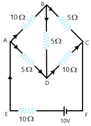
Ans: Current flowing through various branches of the circuit is represented in the given figure.
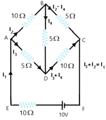

Circuit diagram to calculate the current

Consider

${{I}_{1}}=$Current flowing through the outer circuit

${{I}_{2}}=$Current flowing through branch AB

${{I}_{3}}=$Current flowing through branch AD

${{I}_{2}}-{{I}_{4}}=$Current flowing through branch BC

${{I}_{3}}+{{I}_{4}}=$Current flowing through branch CD

${{I}_{4}}=$Current flowing through branch BD

For the closed circuit ABDA, potential is zero i.e.,

$10{{I}_{2}}+5{{I}_{4}}-5{{I}_{3}}=0$

$2{{I}_{2}}+{{I}_{4}}-{{I}_{3}}=0$

${{I}_{3}}=2{{I}_{2}}+{{I}_{4}}$ …… (1)

For the closed circuit BCDB, potential is zero i.e.,

$5\left( {{I}_{2}}-{{I}_{4}} \right)-10\left( {{I}_{3}}+{{I}_{4}} \right)-5{{I}_{4}}=0$

$5{{I}_{2}}+5{{I}_{4}}-10{{I}_{3}}-10{{I}_{4}}-5{{I}_{4}}=0$

$5{{I}_{2}}-10{{I}_{3}}-20{{I}_{4}}=0$

${{I}_{2}}=2{{I}_{3}}+4{{I}_{4}}$ …… (2)

For the closed circuit ABCFEA, potential is zero i.e.,

$-10+10\left( {{I}_{1}} \right)+10\left( {{I}_{2}} \right)+5\left( {{I}_{2}}-{{I}_{4}} \right)=0$

$10=15{{I}_{2}}+10{{I}_{1}}-5{{I}_{4}}$

$3{{I}_{3}}+2{{I}_{1}}-{{I}_{4}}=2$ …… (3)

From equations (1) and (2), we obtain

${{I}_{3}}=2\left( 2{{I}_{3}}+4{{I}_{4}} \right)+{{I}_{4}}$

${{I}_{3}}=4{{I}_{3}}+8{{I}_{4}}+{{I}_{4}}$

$-3{{I}_{3}}=9{{I}_{4}}$

$-3{{I}_{4}}=+{{I}_{3}}$ …… (4)

Putting equation (4) in equation (1), we obtain

${{I}_{3}}=2{{I}_{2}}+{{I}_{4}}$

$-4{{I}_{4}}=2{{I}_{2}}$ …… (5)

It is evident from the given figure that,

${{I}_{1}}={{I}_{3}}+{{I}_{2}}$ ……. (6)

Putting equation (6) in equation (1), we obtain

$3{{I}_{2}}+2\left( {{I}_{3}}+{{I}_{2}} \right)-{{I}_{4}}=2$

$5{{I}_{2}}+2{{I}_{3}}-{{I}_{4}}=2$ …… (7)

Putting equations (4) and (5) in equation (7), we obtain

$5\left( -2{{I}_{4}} \right)+2\left( -3{{I}_{4}} \right)-{{I}_{4}}=2$

$-10{{I}_{4}}-6{{I}_{4}}-{{I}_{4}}=2$

$17{{I}_{4}}=-2$

${{I}_{4}}=-\frac{2}{17}A$

Equation (4) reduces to

${{I}_{3}}=-3\left( {{I}_{4}} \right)$

${{I}_{3}}=-3\left( -\frac{2}{17} \right)=\frac{6}{17}A$

${{I}_{2}}=-2\left( {{I}_{4}} \right)$

${{I}_{2}}=-2\left( -\frac{2}{17} \right)=\frac{4}{17}A$

${{I}_{2}}-{{I}_{4}}=\frac{4}{17}-\left( -\frac{2}{17} \right)=\frac{6}{17}$

${{I}_{3}}+{{I}_{4}}=\frac{6}{17}+\left( \frac{-2}{17} \right)=\frac{4}{17}A$

${{I}_{1}}={{I}_{3}}+{{I}_{2}}$

$\therefore {{I}_{1}}=\frac{6}{17}+\frac{4}{17}=\frac{10}{17}A$

Therefore, current in branch AB $=\frac{4}{17}A$

Current in branch BC $=\frac{6}{17}A$

Current in branch CD $=\frac{-4}{17}A$

Current in branch AD $=\frac{6}{17}A$

Current in branch BD $=\left( \frac{-2}{17} \right)A$

Total current $=\frac{4}{17}+\frac{6}{17}+\frac{-4}{17}+\frac{6}{17}+\frac{-2}{17}=\frac{10}{17}A$ .


10.

a)  In a metre bridge the balance point is found to be at 39.5 cm from the end A, when the resistor Y is of $12.5\Omega $ . Determine the resistance of X. Why are the connections between resistors in a Wheatstone or meter bridge made of thick copper strips?

Ans: A metre bridge with resistors $X$ and $Y$ is represented in the given figure.


Meter Bridge

A meter bridge works with the same principle as that of a Wheatstone bridge, which is an electrical circuit used to measure unknown resistances. It forms a bridge circuit, wherein the two legs of the circuit are balanced, out of which, one leg has the unknown resistance. Here, the concept of balance point is used, when there is no deflection in the galvanometer (no current flow condition). 

In the above question it is given that:

Balance point from end A is at distance, ${{l}_{1}}=39.5cm$

Resistance of the resistor \[Y=12.5\Omega \] .

Condition for the balance with respect to the given meter bridge is given by

$\frac{X}{Y}=\frac{100-l_1}{l_1}$

$\Rightarrow X=\frac{100-39.5}{39.5}\times 12.5=8.2\Omega $

Thus, the resistance of resistor $X$ is $8.2\Omega $.

The connection between resistors in a Wheatstone or metre bridge is made of thick copper strips which helps to minimize the resistance. Hence it is not taken into consideration in the bridge formula.


b) Determine the balance point of the bridge above if X and Y are interchanged.

Ans: When $X$ and $Y$are interchanged, then ${{l}_{1}}$ and $100-{{l}_{1}}$ also get interchanged.

Thus, the balance point of the bridge would be $100-{{l}_{1}}$ from $A$.

$\therefore 100-{{l}_{1}}=100-39.5=60.5cm$

Clearly, the balance point is $60.5cm$ from $A$.


c)  What happens if the galvanometer and cell are interchanged at the balance point of the bridge? Would the galvanometer show any current?

Ans: When the galvanometer and cell are swapped at the balance point of the bridge, the galvanometer would show zero deflection. As there is null deflection, zero current would flow through the galvanometer.


11. A storage battery of emf 8.0 V and internal resistance $0.5\Omega $ is being charged by a 120 V DC supply using a series resistor of $15.5\Omega $. What is the terminal voltage of the battery during charging? What is the purpose of having a series resistor in the charging circuit?

Ans: In the above question it is given that:

Emf of the storage battery is $E=0.8V$.

Internal resistance of the battery is $r=0.5\Omega $ .

DC supply voltage is $V=120V$

Resistance of the resistor is $R=15.5\Omega $.

Consider effective voltage in the circuit to be $V'$, which would be the difference in the supply voltage and the emf of the battery.

$V'=V-E$

$\Rightarrow V'=120-8=112V$

Now, current flowing in the circuit is $I$ and the resistance $R$ is connected in series to the storage battery. 

Therefore, using Ohm’s law,

$I=\frac{V'}{R+r}$

$\Rightarrow I=\frac{112}{15.5+0.5}=7A$

Thus, voltage across resistor $R$would be:

$IR=7\times 15.5=108.5V$

DC supply voltage = Terminal voltage of battery + Voltage drop across $R$

Terminal voltage of battery $=120-108.5=11.5V$

A series resistor in a charging circuit takes the responsibility for controlling the current drawn from the external source. Excluding this series resistor is dangerous as the current flow would be extremely high if so.


12. In a potentiometer arrangement, a cell of emf 1.25 V gives a balance point at 35.0 cm length of the wire. If the cell is replaced by another cell and the balance point shifts to 63.0 cm, what is the emf of the second cell?

Ans: A potentiometer arrangement facilitates adjustable voltage dividing. It can be used to compare the emf’s of two different cells with the help of balance points in each case. 

Balance point or null point is the point when the galvanometer in the circuit shows no deflection. i.e., when there is no current flowing in the circuit. 

In the above question it is given that when the cell has an emf ${{E}_{1}}=1.25V$, the balance point of the potentiometer is given to be at a distance, ${{l}_{1}}=35cm$. 

Now, when the cell is replaced by another cell of emf ${{E}_{2}}$, the balance point of the potentiometer is given to be at a distance ${{l}_{2}}=63cm$.

The balance condition to compare the emf’s of two cells using a potentiometer setup is given by the relation,

$\frac{{{E}_{1}}}{{{E}_{2}}}=\frac{{{l}_{1}}}{{{l}_{2}}}$

$\Rightarrow {{E}_{2}}={{E}_{1}}\times \frac{{{l}_{1}}}{{{l}_{2}}}$

$\Rightarrow {{E}_{2}}=1.25\times \frac{63}{35}=2.25V$

Clearly, the emf of the second cell is $2.25V$ .


13. The number density of free electrons in a copper conductor estimated in Example 3.1 is $8.5\times {{10}^{28}}{{m}^{-3}}$ . How long does an electron take to drift from one end of a wire 3.0 m long to its other end? The area of cross-section of the wire is $2.0\times {{10}^{-6}}{{m}^{2}}$ and it is carrying a current of 3.0 A.

Ans: In the above question it is given that:

Number density of free electrons in a copper conductor is $n=8.5\times {{10}^{28}}{{m}^{-3}}$.

Length of the copper wire is $l=3.0m$.

Area of cross-section of the wire is $A=2.0\times {{10}^{-6}}{{m}^{2}}$.

Current carried by the wire is $I=3.0A$.

Now we know that:

$I=nAe{{V}_{d}}$

Where,

$e$ is the electric charge of magnitude $1.6\times {{10}^{-19}}C$.

${{V}_{d}}$ is the drift velocity and

\[Drift\text{ }velocity=\frac{\text{Length of the wire }\left( \text{l} \right)}{\text{Time taken to cover }\left( \text{t} \right)}\]

$I=nAe\frac{l}{t}$

$\Rightarrow t=\frac{nAel}{I}$

$\Rightarrow t=\frac{3\times 8.5\times {{10}^{28}}\times 2\times {{10}^{-6}}\times 1.6\times {{10}^{-19}}}{3.0}$

$\therefore t=2.7\times {{10}^{4}}s$ .

Hence the time taken by an electron to drift from one end of the wire to the other is $2.7\times {{10}^{4}}s$.


14. The earth’s surface has a negative surface charge density of ${{10}^{-9}}C{{m}^{-2}}$ . The potential difference of 400 kV between the top of the atmosphere and the surface results (due to the low conductivity of the lower atmosphere) in a current of only 1800 A over the entire globe. If there were no mechanism of sustaining atmospheric electric field, how much time (roughly) would be required to neutralize the earth’s surface? (This never happens in practice because there is a mechanism to replenish electric charges, namely the continual thunderstorms and lightning in different parts of the globe). (Radius of earth = $6.37\times {{10}^{6}}m$.)

Ans: In the above question it is given that:

Surface charge density of the earth is $\sigma ={{10}^{-9}}C{{m}^{-2}}$.

Current over the entire globe is $I=1800A$.

Radius of the earth is $r=6.37\times {{10}^{6}}m$.

Surface area of the earth is given by:

$A=4\pi {{r}^{2}}$

$\Rightarrow A=4\pi \times {{\left( 6.37\times {{10}^{6}} \right)}^{2}}$

$\Rightarrow A=5.09\times {{10}^{14}}{{m}^{2}}$

Charge on the earth surface is given by:

$q=\sigma A$

$\Rightarrow q={{10}^{-9}}\times 5.09\times {{10}^{14}}$

$\Rightarrow q=5.09\times {{10}^{5}}C$

Now, when the time taken to neutralize the surface of the earth is taken to be $t$, then,

Current, $I=\frac{q}{t}$

$\Rightarrow t=\frac{q}{I}$

$\Rightarrow t=\frac{5.09\times {{10}^{5}}}{1800}=282.77s$

Clearly, the time taken to neutralize the surface of the earth is $282.77s$.


15.

a) Six lead-acid type of secondary cells each of emf 2.0 V and internal resistance $0.015\Omega $ are joined in series to provide a supply to a resistance of $8.5\Omega $ . What is the current drawn from the supply and its terminal voltage?

Ans: In the above question, it is given that six lead-acid type of secondary cells are joined in series as shown below:


Six secondary cells

Here, number of secondary cells is $n=6$.

Emf of each secondary cell is $E=2.0V$.

Internal resistance of each cell is $r=0.015\Omega $ .

Series resistor is connected to the combination of cells.

Resistance of the resistor $R$ is $8.5\Omega $.

If the current drawn from the supply is $I$, then 

$I=\frac{nE}{R+nr}$

$\Rightarrow I=\frac{6\times 2}{8.5+6\times 0.015}$

$\Rightarrow I=1.39A$

Now the terminal voltage would be

$V=IR=1.39\times 8.5=11.87V$

Clearly, the current drawn from the supply is $1.39A$ and the terminal voltage is $11.87V$.


b) A secondary cell after long use has an emf of 1.9 V and a large internal resistance of $380\Omega $. What maximum current can be drawn from the cell? Could the cell drive the starting motor of a car?

Ans: It is given that after using a secondary cell for long, emf of the secondary cell is $E=1.9V$.

Also, the internal resistance of the cell is $r = 380\Omega$.

Here, using Ohm’s law, the maximum current $=\frac{E}{r}$

$\Rightarrow \frac{E}{r}=\frac{1.9}{380}=0.005A$.

Clearly, the maximum current used from the cell is $0.005A$. To start the motor of a car, a large amount of current is required. Thus, this cell which produces just 0.005A cannot be used for this purpose.


16. Two wires of equal length, one of aluminium and the other of copper have the same resistance. Which of the two wires is lighter? Hence explain why aluminium wires are preferred for overhead power cables.

${{\rho }_{Al}}=2.63\times {{10}^{8}}\Omega m;{{\rho }_{Cu}}=1.72\times {{10}^{-8}}\Omega m;$$\text{Relative density of Al}=2.7;\text{Relative density of Cu}=8.9$

Ans: In the above question it is given that:

Resistivity of aluminium is ${{\rho }_{Al}}=2.63\times {{10}^{8}}\Omega m$.

Relative density of aluminium is ${{d}_{1}}=2.7$.

Consider ${{l}_{1}}$ to be the length of aluminium wire, ${{m}_{1}}$ as its mass, the resistance of the copper wire as ${{R}_{2}}$, and area of cross-section of the copper wire as ${{A}_{2}}$.

Therefore, using the relation between resistance and resistivity,

${{R}_{1}}={{\rho }_{1}}\frac{{{l}_{1}}}{{{A}_{1}}}$ …… (1)

And 

${{R}_{2}}={{\rho }_{2}}\frac{{{l}_{2}}}{{{A}_{2}}}$ …… (2)

However, we have ${{R}_{1}}={{R}_{2}}$

$\Rightarrow {{\rho }_{1}}\frac{{{l}_{1}}}{{{A}_{1}}}={{\rho }_{2}}\frac{{{l}_{2}}}{{{A}_{2}}}$

Also, we have ${{l}_{1}}={{l}_{2}}$.

\[\Rightarrow \frac{{{\rho }_{1}}}{{{A}_{1}}}=\frac{{{\rho }_{2}}}{{{A}_{2}}}\]

$\Rightarrow \frac{{{A}_{1}}}{{{A}_{2}}}=\frac{{{\rho }_{1}}}{{{\rho }_{2}}}$

$\Rightarrow \frac{{{A}_{1}}}{{{A}_{2}}}=\frac{2.63\times {{10}^{8}}}{1.72\times {{10}^{-8}}}=\frac{2.63}{1.72}$

Now, mass of the aluminium wire is given by:

${{m}_{1}}=Volume\times Density$

$\Rightarrow {{m}_{1}}={{A}_{1}}{{l}_{1}}\times {{d}_{1}}={{A}_{1}}{{l}_{1}}{{d}_{1}}$ …… (3)

Similarly mass of the copper wire is given by:

${{m}_{2}}=Volume\times Density$

$\Rightarrow {{m}_{2}}={{A}_{2}}{{l}_{2}}\times {{d}_{2}}={{A}_{2}}{{l}_{2}}{{d}_{2}}$ …… (4)

Dividing equation (3) by equation (4), we get:

$\frac{{{m}_{1}}}{{{m}_{2}}}=\frac{{{A}_{1}}{{l}_{1}}{{d}_{1}}}{{{A}_{2}}{{l}_{2}}{{d}_{2}}}$

As ${{l}_{1}}={{l}_{2}}$,

$\frac{{{m}_{1}}}{{{m}_{2}}}=\frac{{{A}_{1}}{{d}_{1}}}{{{A}_{2}}{{d}_{2}}}$

As \[\frac{{{A}_{1}}}{{{A}_{2}}}=\frac{2.63}{1.72}\]

$\frac{{{m}_{1}}}{{{m}_{2}}}=\frac{2.63}{1.72}\times \frac{2.7}{8.9}=0.46$

It indicated that ${{m}_{1}}<{{m}_{2}}$.

Clearly, aluminium is lighter than copper.

Since aluminium is lighter, it is prioritized for overhead power cables instead of copper.


17. What conclusion can you draw from the following observations on a resistor made of alloy manganin?

Current (A)

Voltage (V)

Current (A)

Voltage (V)

0.2

3.94

3.0

59.2

0.4

7.87

4.0

78.8

0.6

11.8

5.0

98.6

0.8

15.7

6.0

118.5

1.0

19.7

7.0

138.2

2.0

39.4

8.0

158.0


Ans: From the given table,

The ratio of voltage with current is a constant equal to 19.7. 

Also, manganin is an ohmic conductor, which follows Ohm’s law.

Ohm’s law states that the ratio of voltage with current can be equated to the resistance of the conductor.

Clearly, the resistance of manganin is \[19.7\Omega \].


18. Answer the following questions:

a)  A steady current flow in a metallic conductor of non-uniform cross-section. Which of these quantities is constant along the conductor: current, current density, electric field, drift speed?

Ans: In the above question it is given that a steady current flows in a metallic conductor of non-uniform cross-section. Clearly, the current which flows through the conductor must be constant.

However, current density, electric field, and drift speed are known to be inversely proportional to the cross-sectional area of the conductor. Thus, these quantities cannot be constant.


b) Is ohm’s law universally applicable for all conducting elements? If not, give examples of elements which do not obey Ohm’s law.

Ans: All conducting elements need not satisfy Ohm’s law. For instance, a vacuum diode semiconductor is a conductor which does not follow Ohm’s law. Here, voltage is not proportional to either the current or the resistance.


c) A low voltage supply from which one needs high currents must have very low internal resistance. Why?

Ans: From Ohm’s law, it is known that $V=IR$.

It states that Voltage $\left( V \right)$  is directly proportional to current $\left( I \right)$ .

Clearly, 

$I=\frac{V}{R}$

where, $R$ is the internal resistance of the source. 

Now, when V is less, then R must be very less for a high current used from the source.


d) A high tension (HT) supply of, say, 6 kV must have a very large internal resistance. Why?

Ans: A high tension supply of a very large internal resistance is needed in order to control the current from exceeding the safety limit. 

When the internal resistance is very less, then the current used exceeds the safety limits in case of short circuits.


19. Choose the correct alternative:

a) Alloys of metals usually have (greater/less) resistivity than that of their constituent metals.

Ans: Metal alloys generally have greater resistivity than that of their constituent metals.


b) Alloys usually have much (lower/higher) temperature coefficients of resistance than pure metals.

Ans: Metal alloys generally have lower temperature coefficients of resistance than pure metals.


c) The resistivity of the alloy manganin is (nearly independent of/increases rapidly) with increase of temperature.

Ans: When the temperature is increased, the resistivity of manganin gets no effect. Thus, its resistivity can be considered nearly independent with an increase in temperature.


d) The resistivity of a typical insulator like amber) is greater than that of a metal by a factor of the order of $\left( {{10}^{22}}/{{10}^{3}} \right)$.

Ans: A typical insulator’s resistivity is greater than that of a metal by a factor of the order of ${{10}^{22}}$.


20.

a)  Given n resistors each of resistance R, how will you combine them to get the (i) maximum (ii) minimum effective resistance? What is the ratio of the maximum to minimum resistance?

Ans: In the above question, it is provided that the total number of resistors are $n$ where the resistance of each resistor is $R$.

(i)  When $n$ resistors are connected in series, the effective resistance would be maximum and is considered as the product $nR$. Mathematically, the maximum resistance of the series combination is represented as ${{R}_{1}}=nR$.

(ii)  The effective resistance would be minimum when resistors are connected parallelly. Mathematically, the maximum resistance of the parallel combination is represented ${{R}_{2}}=\frac{R}{n}$.

(iii)  The ratio of the maximum to the minimum resistance would be

$\frac{{{R}_{1}}}{{{R}_{2}}}=\frac{nR}{R/n}={{n}^{2}}$


b) Given the resistances of $1\Omega ,2\Omega ,3\Omega $ , how will you combine them to get an equivalent resistance of (i) $\left( 11/3 \right)\Omega $ (ii) $\left( 11/5 \right)\Omega $ (iii) $6\Omega $ (iv) $\left( 6/11 \right)\Omega $ ?

Ans: In the above question it is provided that: 

${{R}_{1}}=1\Omega ,{{R}_{2}}=2\Omega ,{{R}_{3}}=3\Omega $

(i)  For an equivalent resistance of $\left( 11/5 \right)\Omega $:

Consider the circuit diagram given below.


Equivalent resistance (i)

Equivalent resistance for this circuit would be:

$R'=\frac{2\times 1}{2+1}+3=\frac{2}{3}+3=\frac{11}{3}\Omega$


(ii)  For an equivalent resistance of $\left( 11/3 \right)\Omega $:

Consider the circuit diagram given below.


Equivalent resistance (ii)

Equivalent resistance for this circuit would be:

$R'=\frac{2\times 3}{2+3}+1=\frac{6}{5}+1=\frac{11}{5}\Omega$


(iii)  For an equivalent resistance of $6\Omega $:

Consider the circuit diagram given below.


Equivalent resistance (iii)

Equivalent resistance for this circuit would be:

$R'=1+2+3=6\Omega$


(iv)  For an equivalent resistance of $\left( 6/11 \right)\Omega $ :

Consider the circuit diagram given below.


Equivalent resistance (iv)

Equivalent resistance for the circuit would be:

$R'=\frac{1\times 2\times 3}{1\times 2+2\times 3+3\times 1}=\frac{6}{11}\Omega$


c)  Calculate the equivalent resistance of the following circuit:


circuit to calculate the effective resistance

Ans:  Consider the primary small loop on the left. Two resistors of resistance $1\Omega$ each are connected in series in the upper arm of the loop.

Clearly, their series equivalent resistance $=1+1=2\Omega $.

Also, two resistors of resistance $2\Omega$ each are connected in series in the lower arm of the loop.

Clearly, their series equivalent resistance $=2+2=4\Omega $ .

Now, the circuit can be rearranged to:


Rearrangement of the given circuit

Here $2\Omega $ and $4\Omega $ resistors are connected in parallel in all the newly formed four loops.

Clearly, their parallel equivalent resistance $R'$ is given by,

$R'=\frac{2\times 4}{2+4}=\frac{8}{6}=\frac{4}{3}\Omega $

The circuit further gets rearranged to:


Reduced circuit to calculate the effective resistance

Now, four resistors are connected in series.

Clearly, their series equivalent resistance (or the equivalent resistance of the whole circuit) would be $\frac{4}{3}\times 4=\frac{16}{3}\Omega $.


d)  Calculate the equivalent resistance of the following circuit:


Circuit to calculate the equivalent resistance

Ans: From the given circuit, it is clear that five resistors of resistance $R$ are connected in series. 

Thus, their series equivalent resistance (or the equivalent resistance of the whole circuit)$=R+R+R+R+R=5R$.


21. Determine the current drawn from a 12 V supply with internal resistance $0.5\Omega $ by the infinite network shown in Figure. Each resistor has $1\Omega $ resistance.


Circuit to calculate the current drawn from the supply

Ans: In the above question, it is provided that the resistance of each resistor connected in the given circuit is $R=1\Omega $.

Consider the equivalent resistance of the given circuit to be $R'$.

Because the network is infinite, the equivalent resistance is given by the relation,

$R'=2+\frac{R'}{\left( R'+1 \right)}$

$\Rightarrow {{\left( R' \right)}^{2}}-2R'-2=0$

$\Rightarrow R'=\frac{2\pm \sqrt{12}}{2}=1\pm \sqrt{3}$

As only positive value is acceptable,

$\Rightarrow R'=1+\sqrt{3}$

Internal resistance of the circuit is $r=0.5\Omega $.

Also, total resistance $=2.73+0.5=3.23\Omega $.

Now, with respect to Ohm’s law,

$I=\frac{V}{R}=\frac{12}{3.23}=3.72A$.

Clearly, the current drawn is $3.72A$.


22. Figure shows a potentiometer with a cell of 2.0 V and internal resistance $0.40\Omega $ maintaining a potential drop across the resistor wire AB. A standard cell which maintains a constant emf of 1.02 V (for very moderate currents up to a few mA) gives a balance point at 67.3 cm length of the wire. To ensure very low currents drawn from the standard cell, a very high resistance of $600k\Omega $ is put in series with it, which is shorted close to the balance point. The standard cell is then replaced by a cell of unknown emf $\varepsilon $ and the balance point found similarly, turns out to be at 82.3 cm length of the wire.


Potentiometer circuit

a)  What is the value of $\varepsilon$?

Ans: A potentiometer can be used to compare the emf’s of two cells with the help of balance points, at which there is no current flow in the circuit.

In the above question, it is provided that constant emf of the given standard cell is ${{E}_{1}}=1.02V$.

The balance point on the wire (when the galvanometer shows null deflection) is at a distance ${{l}_{1}}=67.3cm$.

Now, when the cell of unknown emf $\varepsilon $ gets replaced with the standard cell, the new balance point shifts to $l=82.3cm$.

The relationship between emf and balance point in this potentiometer arrangement is given by

$\frac{{{E}_{1}}}{{{l}_{1}}}=\frac{\varepsilon }{l}$

$\Rightarrow \varepsilon =\frac{l}{{{l}_{1}}}\times {{E}_{1}}=\frac{82.3}{67.3}\times 1.02=1.247V$

Clearly, the value of unknown emf is $1.247V$.


b)  What purpose does the high resistance of $600k\Omega $ have?

Ans: A high resistance of $600k\Omega $ is used in order to lessen the current through the galvanometer when the movable contact is distant away from the balance point.


c)  Is the balance point affected by this high resistance?

Ans: No, the balance point would not get affected by the presence of high resistance.


d)  Is the balance point affected by the internal resistance of the driver cell?

Ans: No, the balance point would not get affected by the internal resistance of the driver cell.


e) Would the method work in the above situation if the driver cell of the potentiometer had an emf of 1.0 V instead of 2.0 V?

Ans: When the driver cell of the potentiometer had an emf of $1.0V$ in place of $2.0V$, the given method ceases to work because when the emf of the driver cell of the potentiometer is less than the emf of the other cell, then the balance point refuses to exist on the wire.


f) Would the circuit work well for determining an extremely small emf, say of the order of a few mV (such as the typical emf of a thermos-couple)? If not, how will you modify the circuit?

Ans: To determine an extremely small emf, this arrangement cannot be used. Because of the instability in the circuit, the balance point would be near to end A. Thus, there would be large percentage errors in measurements.
However, the given arrangement can be modified by connecting a series resistance with the wire AB.

When done so, the potential drop across AB would be slightly greater than the measured emf. This facilitates the percentage error to become less.


23. Figure shows a Potentiometer circuit for the comparison of two resistances. The balance point with a standard resistor $R=10.0\Omega $ is found to be 58.3 cm, while that with the unknown resistance X is 68.5 cm. Determine the value of X. What might you do if you failed to find a balance point with the given cell of emf $\varepsilon $ ?


potentiometer circuit for the comparison of two resistances

Ans: In the potentiometer setup, it is provided that:

The resistance of the standard resistor is $R=10.0\Omega$.

The balance point for this resistance is at a distance ${{l}_{1}}=58.3cm$.

Current in the potentiometer wire is $i$.

Hence, potential drop across $R$ is ${{E}_{1}}=iR$.

The resistance of the unknown resistor is $X$.

The balance point for this resistance is at a distance ${{l}_{2}}=68.5cm$.

Hence, potential drop across $X$ is ${{E}_{2}}=iX$.

The relation connecting emf and balance point in a potentiometer bridge circuit is given by

$\frac{{{E}_{1}}}{{{E}_{2}}}=\frac{{{l}_{1}}}{{{l}_{2}}}$

Relating this with our problem,

$\Rightarrow \frac{iR}{iX}=\frac{{{l}_{1}}}{{{l}_{2}}}$

$\Rightarrow X=\frac{{{l}_{1}}}{{{l}_{2}}}\times R=\frac{68.5}{58.3}\times 10=11.749\Omega $ .

Clearly, the value of the unknown resistance $X$ is $11.749\Omega $.

Now, if we couldn’t find a balance point with the given cell of emf $\varepsilon $, then the potential drop across $R$ and $X$ is lessened by putting a resistance in series with it. 

A balance point can be noted only when the potential drop across $R$ or $X$ is smaller than the potential drop across the potentiometer wire AB.


24. Figure shows a 2.0 V potentiometer used for the determination of internal resistance of 1.5 V cell. The balance point of the cell in open circuit is 76.3 cm. When a resistor of $9.5\Omega $ is used in the external circuit of the cell, the balance point shifts to 64.8 cm length of the potentiometer wire. Determine the internal resistance of the cell.


potentiometer

Ans: In the potentiometer setup, it is provided that:

Balance point of the cell in the open circuit is ${{l}_{1}}=76.3cm$.

An external resistance $R$ of resistance $9.5\Omega $ is connected to the circuit.

New balance point of the circuit is at a distance ${{l}_{2}}=64.8cm$ .

Current flowing through the circuit  $=I$ .

In this potentiometer arrangement, the relationship connecting internal resistance of the cell and the two balance points of the bridge setup is:

$r=\left( \frac{{{l}_{1}}-{{l}_{2}}}{{{l}_{2}}} \right)R$

$\Rightarrow r=\left( \frac{76.3-64.8}{64.8} \right)9.5=1.68\Omega$

Clearly, the internal resistance of the cell is $1.68\Omega$ . 


NCERT Solutions for Class 12 Physics Chapter 3 PDF Download

By studying chapter 3 Physics class 12, students will get to learn about the circuit diagrams, illustrations, energy diagrams and graphs along with day to day examples to make the topic simpler. This chapter also teaches that current is a scalar quantity, germanium obey Ohm's law, Kirchhoff's rule is established on conservation of charge, etc.

To get accustomed to these concepts, students should download the Current Electricity class 12 NCERT Books Solutions PDF, entirely free of cost. This study material acts as a useful tool to score well in the board exam.


NCERT Class 12 Physics Solutions - Free PDF Download


List of Topics Covered Under NCERT Solutions for Class 12 Physics Chapter 3  Current Electricity

The below list shows the important topics covered in the chapter Current electricity. This chapter completely explains how the electricity passes through the conductor, the conductor’s response to the electricity, What is resistivity, how cells are working, what will be the response of the cell while connecting in series or parallel, how the current flow is calculated and all other related information in detail. 

  • Electric Current

  • Electric Currents in Conductors

  • Ohm’s law

  • Drift of Electrons and the Origin of Resistivity

  • Limitations of Ohm’s Law

  • Resistivity of Various Materials

  • Temperature Dependence of Resistivity

  • Electrical Energy, Power

  • Combination of Resistors — Series and Parallel

  • Cells, emf, Internal Resistance

  • Cells in Series and in Parallel

  • Kirchhoff’s Rules

  • Wheatstone Bridge

  • Meter Bridge

  • Potentiometer


Important Formulas in  Class 12 Physics Chapter 3  Current Electricity

Students who are preparing for the board exams and competitive exams can have a brush up on important formulas in the entire lesson. 


NCERT Solutions for Class 12 Physics Chapter 3 Current Electricity

The Current Electricity class 12 solutions PDF contains a total of 24 questions comprising numerical, derivations and subjective type questions, which are entirely based on the below-mentioned concepts of the chapter. Take a look!

  • Current Electricity Class 12: Introduction

The introductory section gives students an overall idea of Current Electricity.

  • Electric Current in Conductor

Here, students will gain knowledge about how electric current passes across conductors. With the help of this section, students will get to learn that electrical current is nothing but the flow of charge from one point to another.

  • Current Electricity Class 12: Ohm's Law and its Various Applications

In this part, students will get accustomed to the Ohm's Law, and its various applications in solving numerical problems. It would help to solve the questions related to Ohm's Law from the NCERT solution class 12 Physics chapter 3 PDF to clear your concepts of the same. Furthermore, students will also learn about the restrictions of Ohm's Law.

  • Electron Drift and Resistivity Origin, and Mobility

These portions provide an idea about the average velocity obtained by the charged particles, use of resistivity in solving various problems and mobility of electrons helps to pass an electric current.

  • Current Electricity Class 12: Resistivity of Different Materials

In the solutions PDF, there are quite a few questions related to resistivity of materials which gives you an idea about how to proceed with the numerical. The solutions are provided in a step by step manner so that it becomes feasible for you to comprehend the same.

  • Electrical Energy

Here, students will acquire knowledge about the role of charged particles (electrons) in electrical power.

  • Current Electricity Class 12: Series and Parallel Resistors

Questions of series and parallel resistors are explained in a straightforward manner, which will help you to master the difference between them. Real-life series and parallel combination examples are given like:

(Image will be uploaded soon)

  • Cells, Internal Resistance and EMF

Different kinds of problems are given on EMF, cells and internal resistance and the answers are also elucidated straightforwardly.

  • Current Electricity Class 12: Kirchhoff’s Rule

The questions from this section are about how Kirchhoff's Law deals with potential difference and current.

  • Wheatstone Bridge

Numerical based on Wheatstone Bridge will help a student learn how a Meter Bridge works, and how it can be utilised to determine unknown resistance.

  • Current Electricity Class 12: Potentiometer

Here, students will have an idea about the potentiometer, and how its three-terminal resistor gives rise to an adjustable voltage.


Current Electricity Class 12 Board Exam: Marks Distribution

The chapter – Current Electricity holds seven marks in the CBSE 12 board exam, and the type of questions that are expected to come are in the form of very short answers, short answer I and II, value-based questions and long answer questions.

Benefits of NCERT Solutions Class 12 Physics Chapter 3 Current Electricity

  • These NCERT Solutions are prepared by the top teachers of India so that students can refer to these solutions whenever they are stuck with any question given in the exercises.

  • These solutions are as per the updated CBSE guidelines for Class 12. Hence, students can get a clear understanding of how to answer various types of questions in their 12th Board Physics exam.

  • Our subject experts have come up with the most effective problem-solving methods in these solutions, which will help students to answer the questions in a short time during the exam. The step-wise solutions for numerical-value based questions will help students to get a better understanding of the application of the concepts of Current Electricity.

  • By referring to these NCERT Solutions, students will be able to get a clear idea of the derivation and application of the current electricity formulas. These solutions will ultimately help students to answer the questions logically and accurately in their exams.

  • These NCERT Solutions are available in a PDF format for easy access of students. This PDF can be downloaded for free from our mobile app as well as the website. Thus, students can refer to these solutions any time from anywhere.


Why Vedantu?

Vedantu brings together the top teachers and subject experts of India to provide a seamless learning experience for students. You will get study materials like NCERT Solutions, CBSE Class 12 Physics Revision Notes, Important Questions for Class 12 Physics, CBSE Class 12 Physics sample papers, CBSE Class 12 Physics previous years’ question papers with solutions, NCERT Exemplar Solutions, reference book solutions, etc. on Vedantu for your 12th Board Physics exam preparation. We provide similar study materials for the other subjects of CBSE Class 12 as well. 


We also provide useful study materials for JEE and NEET. Our study materials are available for free of cost and all you need to do is register on Vedantu to access these study materials. You can also sign up for 1:1 online classes and the other online classes on Vedantu to get the guidance of our teachers and mentors for your exam preparation.


Conclusion

Vedantu's NCERT solutions for Class 12 Physics Current Electricity provide comprehensive and reliable support to students. These solutions are meticulously crafted by expert educators to help students understand and solve complex problems related to current electricity. With detailed explanations and step-by-step solutions, students can enhance their conceptual understanding and problem-solving skills. Vedantu's NCERT solutions cover all the chapters and exercise questions from the textbook, allowing students to practice and revise effectively. Whether it's understanding Ohm's law, Kirchhoff's laws, or solving circuit-related problems, Vedantu's NCERT solutions serve as a valuable resource for Class 12 Physics students, aiding them in their exam preparation and overall academic growth.

FAQs on NCERT Solutions for Class 12 Physics Chapter 3 - Current Electricity

1. Which Topics are Covered in Current Electricity?

This chapter primarily deals with the first motion laws, second motion laws, Newton's third motion laws, pseudo forces, the horse and cart and inertia. Moreover, students will also become familiar with electric current, Ohm's law, electric current in conductors, the origin of resistivity, the drift of electrons, Ohm's law limitations, mobility, the resistivity of different materials, electrical power and energy and temperature vulnerability of resistivity.


By studying Current Electricity, students will also get to learn about the resistor combination in both parallel and series, cells, internal resistance, emf, Kirchhoff’s rule, Wheatstone bridge, potentiometer and meter bridge. Some other topics included in this chapter are non-conservation and conservation force field, work-energy theorem, kinetic energy, types of power and equilibrium, the law of conservation of mechanical energy, etc.

2. What is Meant by a Wheatstone Bridge?

This device is utilised to observe mechanical and electrical quantities. In other words, Wheatstone Bridge is a tool for light measurement with the help of a photo resistive instrument. A light-dependent resistor is a type of sensor which is passive-resistive. It is used to convert light levels to change in resistance, and eventually to voltage.


The circuit of the Wheatstone bridge has many applications today. Along with the current functional amplifiers, the Wheatstone Bridge can be used to interface different sensors and transducers into amplifier circuits.

3. How to Obtain Full Marks in Class 12 Physics?

In order to achieve the full score in the Class 12 Physics exam, the primary requirement is to study the NCERT thoroughly. Also, students must practise multiple choice questions from NCERT and recommended books.


Preparing a formula chart is vital for the learners to practise the numerical problems, and diagrams must also be practised with proper labelling. In the case of long answer questions, students must refrain from writing long paragraphs; instead, they must write in bullet points. Further, solving previous years question papers is also mandatory to score well.

4. How to prepare Class 12 Physics Chapter 3 well for exams?

Current Electricity in Physics for Class 12 can often confuse students due to the many laws and numerical in the chapter. To prepare this chapter well for exams, first, go through all the topics thoroughly. Clear the concepts and solve the numerical problems. Solve the exercises in the books and then re-check them with NCERT Solutions so you can get an idea of how to answer questions in the exams. Make notes so that the revision becomes easier.

5. How can I make a study plan for Class 12 Physics Chapter 3?

Class 12 Chapter 3 can be stressful for the students, so forming a good study plan is very important. To make a study plan for Physics, follow these steps:

  • Mark the topics you find difficult and give them more time.

  • Solve some numerical problems every day.

  • Study at odd hours of the day.

  • Take breaks in between to soak in all you have studied.

  • Make notes as you go through the chapters.

6. Where can I download Physics NCERT Solutions for Class 12 Chapter 3 PDF?

You can download the PDF for Physics NCERT Solutions for Class 12: Chapter 3 using the official website of Vedantu or the Vedantu app. Vedantu provides all the study material free of cost. Visit NCERT Solutions chapter 3 Current and Electricity and you will land on the page with chapter-wise solutions. Choose Chapter 3: Current Electricity. Thereafter, you will be able to download the NCERT Solution and other study material for the chapter. These solutions can be a student's best study buddy as they help in providing the best guidance and make learning fun.

7. Why are the Class 12 Physics Chapter 3 NCERT Solutions important?

NCERT Solutions for Chapter 3 “Current Electricity” in Class 12 Physics is essential for the exams and can often confuse the students. Using the solutions will help you clear all the concepts and guide you in solving the numerical problems. They also give you a fair idea about the type of questions in exams and how to answer them. It is essential to be well-prepared for the exams and NCERT Solutions are the best guidance you can find online.

8. Do I need to practice all the questions provided in Class 12 Physics NCERT Solutions of Chapter 3?

Solving all the questions provided in Chapter 3 of Class 12 Physics NCERT Solutions will help you comprehend the concepts in the chapter intensively and clear your doubts. The answers to the questions from the NCERT textbook in the solutions are designed following the CBSE board guidelines by experts in each subject. Therefore, solving and practising all of them regularly will bring you a step closer to achieving good marks in the exams.