


Physics Notes for Chapter 6 Electromagnetic Induction Class 12 - FREE PDF Download


PDF Summary - Class 12 Physics Electromagnetic Induction Notes (Chapter 6)
Section-A (1 Mark Questions)
1. A metallic wire coil is stationary in a uniform magnetic field. What is the emf induced in the coil
Ans. No emf is induced in the coil as there is no change in the magnetic flux linked with the coil.
2. Why does metallic piece become very hot when it is surrounded by a coil carrying high frequency (H.F) alternating current?
Ans. When a metallic piece is surrounded by a coil carrying high frequency (H.F) alternating current, it becomes hot because eddy currents are produced which in turn produces joule’s heating effect.
3. The induced emf is also called back emf. Why?
Ans. It is because induced emf produced in a circuit always opposes the cause which produces it.
4. The electric current flowing in a wire in the direction from B to A Find out the direction of the induced current in the metallic loop kept the wire as shown in the figure.
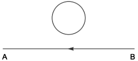
Ans. According to Lenz’s law, the direction of induced current will oppose the cause of its production. So, the current in loop will induce in such a way that it will support the current flowing in the wire i.e., in the same direction. So, the direction of current in the loop will be clockwise.
5. Two spherical bobs, one metallic and the other of glass, of the same size are allowed to fall freely from the same height above the ground. Which of the two would reach earlier and why?
Ans. The glass bob will reach earlier on ground as acceleration due to gravity is independent of mass of the falling bodies. Being insulator, no induced current is developed in it due to the earth’s magnetic field.
6. The closed loop PQRS of wire is moved into a uniform magnetic field at right angles to the plane of the paper as shown in the figure. Predict the direction of the induced current in the loop.
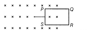
Ans. Since, magnetic flux increasing when the loop moves into uniform magnetic field. So, the induced current should oppose this increase. Thus, flow will be from QPSRQ. i.e. anti-clockwise.
7. State the Faraday’s law of electromagnetic induction.
Ans. First law: Whenever a conductor is placed in a varying magnetic field, EMF induces and this emf is called an induced emf and if the conductor is a closed circuit than the induced current flows through it.
Second law: The magnitude of the induced EMF is equal to the rate of change of flux linkages.
8. Write S.I. unit of magnetic flux. Is it a scalar or a vector?
Ans. SI unit of Magnetic flux is Weber. It is a Scalar quantity.
9. On what factors does the self-inductance of a solenoid depends?
Ans. Factors on which self-inductance depends:
(a) No of turns in the solenoid
(b) Length of the solenoid
(c) Core inside the solenoid
(d) Area of the cross-section.
10. Define self–induction of a coil. Give one example.
Ans. The phenomenon of electric current in a coil due to growth or decay of current in the coil.
Example: Choke Coil.
Section-B (2 Marks Questions)
11. A bar magnet falls from a height ‘h’ through a metal ring. Will its acceleration be equal to g? Give reason for your answer.
Ans. Acceleration will be less than ‘g’ because of induction of current in the coil as stated by Lenz’s Law which opposes the falling of magnet.
12. If the change in flux through the loop in time △t is △Φ and the resistance of loop be ‘r’. Find out the amount of charge flowing through the conductor in time △t.
Ans. $\varepsilon =-\dfrac{\Delta \theta }{\Delta t}$
current(I)= $\dfrac{\left | \varepsilon \right |}{r}=\dfrac{1}{r}\dfrac{\Delta \theta }{\Delta t}$
or, $\dfrac{\Delta Q}{\Delta T}=\dfrac{1}{r}\dfrac{\Delta \phi }{\Delta t}$
or, $\Delta Q=\dfrac{\Delta \phi }{r}$ .
13. Mention one advantage of eddy current.
Ans. Magnetic braking in trains: Strong electromagnets are situated above the rails in some electrically powered trains. When the electromagnets are activated, the eddy currents induced in the rails oppose the motion of the train. As there are no mechanical linkages, the braking effect is smooth.
14. Name two scientists who concluded electric currents were induced in closed coils when subjected to changing magnetic fields by performing experiments.
Ans. Michael Faraday in England and Joseph Henry in USA.
15. State Lenz’s Law. On which fundamental principle is the law based upon.
Ans. The polarity of induced emf is such that it tends to produce a current which opposes the change in magnetic flux that produced it
16. Suppose we bring a bar magnet near a coil and the North Pole of the bar magnet is facing the coil. In what direction the current is induced in the coil?
Ans. Current will be induced in the anticlockwise direction in the coil.
PDF Summary - Class 12 Physics Electromagnetic Induction Notes (Chapter 6)
1.
 :
:
1. The magnetic flux associated with an area placed in a magnetic field is equal to the total number of magnetic lines of force passing naturally through that area.
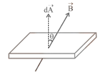
2. Net flux through the surface $\phi=\oint \overrightarrow{\mathrm{B}} \cdot \mathrm{d} \overrightarrow{\mathrm{A}}=\mathrm{B} \mathrm{A} \cos \theta$
( $\theta$ is the angle between area vector and magnetic field vector)
If $\theta=0^{\circ}$ then $\phi=B A$, If $\tau$ $\theta=90^{\circ}$ then $\phi=0$
3. Unit and Dimension i Magnetic flux is a scalar quantity. It's S.I. the unit is Weber (Wb), CGS unit is Maxwell or Gauss $\times \mathrm{cm}^{2}$ ($1 w b=108$ Maxwell).
4. Other units:
$\mathrm{Tesla} \times \mathrm{m}^{2}=\frac{\mathrm{N} \times \mathrm{m}}{\text { Amp }}=\frac{\text { Joule }}{\text { Amp }}=\frac{\text { Volt } \times \text { Coulomb }}{\text { Amp }}$
$=$ Volt $\times$ sec $=\mathrm{ohm} \times$ Coulomb $=$ Henry $\times$ Ampere
It's dimensional formula, $[\phi]=\left[\mathrm{ML}^{2} \mathrm{~T}^{-2} \mathrm{~A}^{-1}\right]$
2. Faraday's Laws of Emi
(1) First law:
An induced emf is formed in a circuit whenever the number of magnetic lines of force (magnetic flux) travelling through it changes. The induced emf lasts only as long as the flux is changing or being cut.
(2) Second law:
The induced emf is calculated from the rate of change of magnetic flux in the circuit, i.e. $\mathrm{e}=-\frac{\mathrm{d} \phi}{\mathrm{dt}} \cdot \operatorname{For} \mathrm{N}$ turns $\mathrm{e}=-\frac{\mathrm{Nd} \phi}{\mathrm{dt}}$; Negative sign indicates that induced $\operatorname{emf}(e)$ opposes the change of flux.
Induced current(i) | Induced Charge(q) | Induced Power(P) |
\[\text{i}=\frac{\text{e}}{\text{R}}=-\frac{\text{N}}{\text{R}}\cdot \frac{\text{d}\phi }{\text{dt}}\]
| \[\text{dq}=\text{idt}=-\frac{\text{N}}{\text{R}}\cdot \text{d}\phi \] Induced charge is time independent. | \[\text{P}=\frac{{{\text{e}}^{2}}}{\text{R}}=\frac{{{\text{N}}^{2}}}{\text{R}}{{\left( \frac{\text{d}\phi }{\text{dt}} \right)}^{2}}\] It depends on time and resistance. |
Various Methods of Producing induced E.M.F.
We have learnt that e.m.f. is induced in a circuit, whenever the amount of magnetic flux linked with the circuit is changed. As $\phi=B A \cos \theta$, the magnetic flux $\phi$ can be changed by changing $B, A$ or $\theta$
Hence there are three methods of producing induced e.m.f
1. By adjusting the magnetic field B's magnitude,
2. By altering region $A$, i.e., shrinking, stretching, or modifying the coil's shape.
3. By changing the angle between the direction of $B$ and the normal to the surface area $A$, i.e. modifying the surface area and magnetic field's relative orientation.
3. Lenz's Law
The induced emf/induced current direction is determined by this law.
The direction of induced emf or current in a circuit, according to this law, is such that it opposes the source that generates it. The law of conservation of energy underpins this rule.
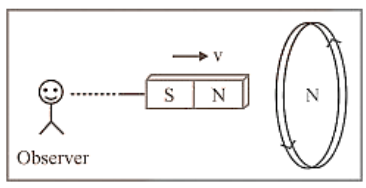
(1) When the $N$-pole of a bar magnet advances towards the coil, the flux associated with the loop increases, causing an emf. Induced current flows through the loop circuit since it is closed.
(2) Because the approaching north pole is the cause of this induced current, the induced current in the loop is directed in such a way that the front face of the loop behaves like the north pole. Therefore induced current as seen by the observer $O$ is an anticlockwise direction.
(3) The cause of generated emf in the coil can also be referred to as relative motion if the loop is free to move. As a result, the relative motion between the two objects works against the cause.
The loop and the incoming magnet should be in opposition. As a result, the loop will begin to move in the direction of the magnet is moving.
(4) It is critical to keep in mind that whenever the reason of induced the new motion is always in the direction of the emf.
Position of magnet | 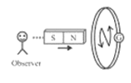
| 
| 
| 
| |
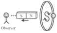
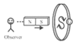
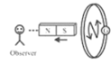
The direction of induced current | Anticlockwise direction | Clockwise direction | Clockwise direction | Anticlockwise direction | |
The behaviour of face of the coil | As a north pole | As a south pole | As a south pole | As a north pole | |
Type of magnetic force opposed | Repulsive force | Attractive force | Repulsive force | Attractive force | |
Magnetic field linked with the coil and its progress as viewed from left | Cross($\times$), Increases | Cross($\times$), Decreases | Cross($\times$), Increases | Cross($\times$), Decreases | |
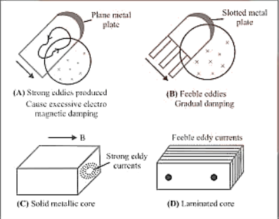
4. Eddy Current
When a changing magnetic flux is given to a large piece of conducting material, it induces circling currents known as eddy currents. Eddy currents have huge magnitudes and heat up the conductor because the bulk conductor's resistance is usually low.
(1) These are circulating currents, similar to water eddies.
(2) The "Foucault current" is named after Focault's experimental hypothesis.
(3) In a metallic block, the generation of eddy currents results in the loss of electric energy in the form of heat.
(4) As a result of the lamination and slotting processes, the resistance channel for eddy current circulation increases, weakening and lowering them and also reducing losses caused by them.
Eddy Current Applications:
Although eddy currents are generally unwelcome, they do have some helpful applications, as listed below.
(i) Dead-Beat Galvanometer:
When a current is delivered via its coil, a deadbeat galvanometer's pointer comes to rest in the final equilibrium position instantaneously, with no oscillation around the equilibrium position.
This is accomplished by winding the coil around a metallic frame, which induces significant eddy currents that give electromagnetic damping.
(ii) When the train is running, the wheel moves in the air; when the train is stopped by electric brakes, the wheel is made to move in an electromagnet created field. Eddy currents created in the wheels as a result of the changing flux work against the cause and bring the train to a halt.
(iii) Induction Furnace:
The heat of Joule causes a metal item to melt when it is placed in a rapidly changing magnetic field.
(iv) Speedometer:
In an automobile's speedometer, a magnet is geared to the vehicle's main shaft and rotates in accordance with the vehicle's speed. Hair springs are used to secure the magnet in an aluminium cylinder. When the magnet rotates, it produces eddy currents in the drum and drags it through an angle, which indicates the speed of the vehicle on a calibrated scale.
(v) Energy Metre:
The armature coil of an energy meter has a metallic aluminium disc that rotates between the poles of a pair of permanent horseshoe magnets. The current induced in the disc as the armature spins tend to oppose the motion of the armature coil. Deflection is proportional to the energy consumed due to this braking effect.
5. Induced Charge Flow
When a current is induced in the circuit due to the flux change, charge flows through the circuit and the net amount of charge which flows along the circuit is given as:
$\mathrm{q}=\int \mathrm{idt}=\int \frac{1}{\mathrm{R}}\left|\frac{\mathrm{d} \phi}{\mathrm{dt}}\right| \mathrm{dt}=\frac{1}{\mathrm{R}} \int \mathrm{d} \phi$ $\mathrm{q}=\frac{|\Delta \phi|}{\mathrm{R}}$ and $\mathrm{q}=\mathrm{N} \frac{|\Delta \phi|}{\mathrm{R}}$ for $\mathrm{N}$ tums.
6. Induced Electric Field
It is non-conservative and non-electrostatic in nature. Its field lines are concentric circular closed curves.
A time varying magnetic field dt dB always produces an induced electric field in all space surrounding it. Induced electric field $\left(E_{i n}\right)$ is directly proportional to induced emf so $e=\oint \vec{E}_{\text {in }} \cdot \overrightarrow{d \bar{\ell}} \quad \ldots$ (i)
From Faraday's second laws $\quad \mathrm{e}=-\frac{\mathrm{d} \phi}{\mathrm{dt}} \quad$ wu (ii)
From (i) and (ii)
$\quad \mathrm{e}=\oint \overrightarrow{\mathrm{E}}_{\mathrm{in}} \cdot \mathrm{d} \overrightarrow{\mathrm{d}}=-\frac{\mathrm{d} \phi}{\mathrm{dt}}$.
This is known as an integral form of Faraday's laws of EMI.
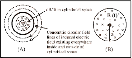
A uniform but time-varying magnetic field $B(t)$ exists in a circular region of radius ' $a$ ' that is directed into the plane of the paper as shown, and the magnitude of the induced electric field $\left(E_{\text {in }}\right.$ ) at point $P$, which is located at a distance $r$ from the circular region's centre, is calculated as follows:
$\oint \vec{E}_{\text {in }} \cdot \overrightarrow{\mathrm{d}} \vec{\ell}=\mathrm{e}=\frac{\mathrm{d} \phi}{\mathrm{dt}}=\mathrm{A} \frac{\mathrm{dB}}{\mathrm{dt}}$
i.e. \[\text{E}(2\pi r)=\pi {{\text{a}}^{2}}\frac{\text{dB}}{\text{dt}}\]
where \[r\ge a\text{ }\!\!~\!\!\text{ or }\!\!~\!\!\text{ }E=\frac{{{a}^{2}}}{2r}\frac{dB}{dt};{{E}_{\text{in }\!\!~\!\!\text{ }}}\propto \frac{1}{r}\]
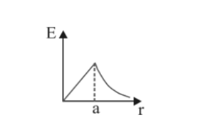
$\text { when } \mathrm{r}<\mathrm{a} ; \mathrm{E}=\frac{\mathrm{r}}{2} \frac{\mathrm{dB}}{\mathrm{dt}} ; \mathrm{E}_{\mathrm{n}} \propto \mathrm{r}$
7. Dynamic (motional) Emi Due to Translatory Motion:
(1) Consider a conducting rod of length $l$ moving with $a_{\infty}$ uniform velocity $\vec{v}$ perpendicular to a uniform magnetic field $\vec{B}$, directed into the plane of the paper. Let the rod be moving to the right as shown in the figure. The conducting electrons also move to the right as they are trapped within the rod.
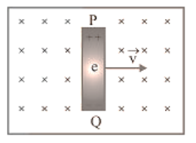
Conducting electrons experiences a magnetic force $F_{m}=e v B$. So they move from $P$ to $Q$ within the rod. The end $P$ of the rod becomes positively charged while end $Q$ becomes negatively charged, hence an electric field is set up within the rod which opposes the further downward movement of electrons i.e. an equilibrium is reached and in equilibrium $F_{c}=F_{m}$ i.e. $e E=e v B$ or $E=v B$ Induced $\operatorname{emf} \mathrm{e}=\mathrm{E} l=\mathrm{Bv} l\left[\mathrm{E}=\frac{\mathrm{V}}{\ell}\right]$
(2) If rod is moving by making an angle theta with the direction of magnetic field or length. Induced $\operatorname{emf} \mathrm{e}=\mathrm{B} v l \sin \theta$

(3) Motion of conducting rod on an inclined plane: When conductor starts sliding from the top of an inclined plane as shown, it moves perpendicular to its length but at an angle $(90-\theta)$ with the direction of magnetic field.
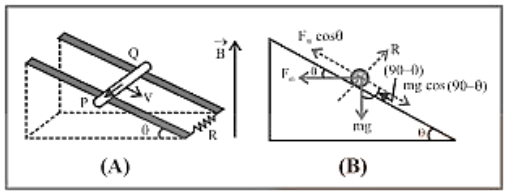
Hence induced emf across the ends of conductor $\mathrm{e}=\operatorname{Bv} \sin (90-\theta) l=\operatorname{Bv} l \cos \theta$
The forces acting on the bar are shown in the following figure. The rod will move down with constant velocity only if $\mathrm{F}_{\mathrm{m}} \cos \theta=\mathrm{mg} \cos (90-\theta)=\mathrm{mg} \sin \theta$
$\Rightarrow B i l \cos \theta=m g \sin \theta$
$\Rightarrow \mathrm{B}\left(\frac{\mathrm{Bv}_{\mathrm{T}}(\cos \theta}{\mathrm{R}}\right) \ell \cos \theta \mathrm{mg} \sin \theta=>\mathrm{v}_{\mathrm{T}}=\frac{\mathrm{mgR} \sin \theta}{\mathrm{B}^{2} \ell^{2} \cos ^{2} \theta}$
8. Motional Emi in Loop by Generated Area:
If a conducting rod passes along two parallel conducting rails as illustrated in the diagram, the phenomena of induced emf may also be explained using the idea of the generated area (the area swept by a conductor in a magnetic field while it moves).

As shown in the figure in time t distance travelled by conductor $=v t$ Area generated $A=l v t.$
Flux linked with this area $\phi=B A=B l v t$
(1) Induced current:
$\mathrm{i}=\frac{\mathrm{e}}{\mathrm{R}}=\frac{\mathrm{Bv} \ell}{\mathrm{R}}$
(2) Magnetic force :
Conductor $P Q$ experiences a magnetic force in opposite direction of it's motion and
$\mathrm{F}_{\mathrm{m}}=\mathrm{Bi} \ell=\mathrm{B}\left(\frac{\mathrm{Bv} \ell}{\mathrm{R}}\right) \ell=\frac{\mathrm{B}^{2} \mathrm{v} \ell^{2}}{\mathrm{R}}$
(3) Power dissipated in moving the conductor :
For uniform motion of rod $\mathrm{PQ}$, the rate of doing mechanical work by external agent or mech. Power delivered by external source is given as
$P_{\mathrm{mect}}=P_{e x}=\frac{d W}{d t}=F_{\mathrm{ext}} \cdot v=\frac{B^{2} v \ell^{2}}{R} \times v=\frac{B^{2} v^{2} \ell^{2}}{R}$
(4) Electrical power :
Also electrical power dissipated in resistance or rate of heat dissipation across resistance is given as
$P_{\text {tecmal }}=\frac{H}{t}=i^{2} R=\left(\frac{B v \ell}{R}\right)^{2} \cdot R ; \quad P_{\text {tecmal }}=\frac{B^{2} v^{2} \ell^{2}}{R}$
(It is clear that $P_{\text {mech. }}=P_{\text {teemmal }}$ which is consistent with the principle of conservation f energy.)
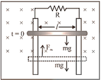
(5) Motion of conductor rod in a vertical plane :
If conducting rod released from rest (at $t=0$ ) as shown in figure then with rise in it's speed $(v)$, induces $\operatorname{emf}(e)$, induced current $(i)$, magnetic force $\left(F_{m}\right)$ increases but it's weight remains constant. Rod will achieve a constant maximum (terminal) velocity,
$\mathrm{v}_{\mathrm{T}}$ if $\mathrm{F}_{\mathrm{m}}=\mathrm{mg}$
So, $\frac{B^{2} v_{\mathrm{T}}^{2} \ell^{2}}{R}=m g \quad \Rightarrow v_{T}=\frac{m g R}{B^{2} \ell^{2}}$
Special Cases:
The motion of train and aeroplane in earth's magnetic field.
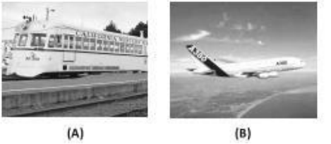
Induced emf across the axle of the wheels of the train and it is across the tips of the wing of the aeroplane is given by $e=B l v$ where $l=$ length of the axle or distance between the tips of the wings of plane, $B_{v}=$ vertical component of earth's magnetic field and $v=$ speed of train or plane.
9. Motional Emi Due to Rotational Motion-
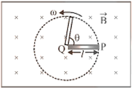
(1) Conducting Rod :
A conducting rod of length 1 whose one end is fixed, is rotated about the axis passing through it's fixed end and perpendicular to its length with constant angular velocity $\omega$. Magnetic field $(B)$ is perpendicular to the plane of the paper. emf induced across the ends of the rod where $v=$ frequency (revolution per sec) and $T$ = Time period.
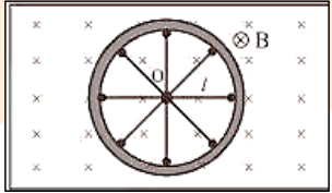
(2) Cycle Wheel:
A conducting wheel each spoke of length $l$ is rotating with angular velocity in a given magnetic field as shown below in fig. Due to flux cutting each metal spoke becomes an identical cell of emf e (say), all such identical cells connected in parallel fashion $e_{n e t}=e$ (emf of single cell). Let $\mathrm{N}$ be the number of spokes hence $\mathrm{e}_{\mathrm{nat}}=\frac{1}{2} \mathrm{~B} \omega \ell^{2} ; \omega=2 \pi \mathrm{V}$
Here $\mathrm{e}_{\text {ac }} \propto \mathrm{N}^{0}$ i.e. total emf does not depend on number of spokes $N$.
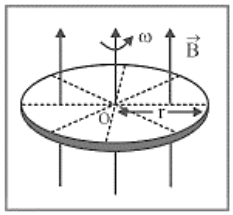
(3) Faraday Copper Disc Generator :
A metal disc can be assumed to made of uncountable radial conductors when metal disc rotates in transverse magnetic field these radial conductors cuts away magnetic field lines and because of this flux cutting all becomes identical cells each of emf ' $e$ '
where $\quad \mathrm{e}=\frac{1}{2} \mathrm{~B} \omega \mathrm{r}^{2}$
(4) Semicircular conducting loop i If a semi-circular conducting loop (ACD) of radius ' $r^{\prime}$ ' with center at $O$, the plane of loop being in the plane of paper. The loop is now made to rotate with a constant angular velocity $\omega$, about an axis passing through $O$ and perpendicular to the plane of paper. The effective resistance of the loop is $R$.

(5) In time t the area swept by the loop in the field i.e. region II
$A=\frac{1}{2} r(r \theta)=\frac{1}{2} r^{2} \omega t ; \frac{d A}{d t}=\frac{r^{2} \omega}{2}$
Flux link with the rotating loop at time t $_{2} \phi=B A$
Hence induced emf in the loop in magnitude $|e|=\frac{\mathrm{d} \phi}{\mathrm{dt}}=\mathrm{B} \frac{\mathrm{d} \mathrm{A}}{\mathrm{dt}}=\frac{\mathrm{B} \omega \mathrm{r}^{2}}{2}$ and induced current i $=\frac{|\mathrm{e}|}{\mathrm{R}}=\frac{\mathrm{B} \omega \mathrm{r}^{2}}{2 \mathrm{R}}$
10. Periodic Emi
Suppose a rectangular coil having $N$ turns placed initially in a magnetic field such that magnetic field is perpendicular to its plane as shown-
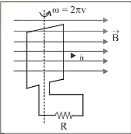
Where,
$\omega$-Angular speed
$v$-Frequency of rotation of coil $R$-Resistance of coil
For uniform rotational motion with, the flux linked with coil at any time $t$, $\phi=\mathrm{NBA} \cos \theta=\mathrm{NBA} \cos \omega \mathrm{t}$
$\phi=\phi_{0} \cos \omega$ there $\phi_{0}=\mathrm{NBA}=$ maximum flux
(1) Induced Emf in Coil :
Induced emf also changes in periodic manner that's why this phenomenon called periodic EMI
$\mathrm{e}=-\frac{\mathrm{d} \phi}{\mathrm{dt}}=\mathrm{NBA} \omega \sin \omega \mathrm{t}=e=e_{0} \sin \omega t$ where $e_{0}=e m f$
amplitude or max. emf $=\mathrm{NBA} \omega=\phi_{0} \omega$
(2) Induced Current :
At any time $t, i=\frac{e}{R}=\frac{e_{0}}{R} \sin \omega t=i$
$\sin \omega t$ where $i_{0}=$ current amplitude or max. current
$\mathrm{i}_{0}=\frac{\mathrm{e}_{0}}{\mathrm{R}}=\frac{\mathrm{NBA} \omega}{\mathrm{R}}=\frac{\phi_{0} \omega}{\mathrm{R}}$
11. Inductance-
(1) Inductance is an electrical circuit property that opposes any change in the circuit's current.
(2) Inductance is a feature of electrical circuits that is intrinsic. Whether we desire it or not, it will always be found in an electrical circuit.
(3) The inductance of a straight wire carrying electricity with no iron portion in the circuit will be lower.
(4) Inductance in an electrical circuit is akin to inertia in mechanics, because inductance opposes any change in current in the circuit.
11.1 Self Induction-
Whenever the electric current passing through a coil or circuit changes, the magnetic flux linked with it will also change. As a result of this, in accordance with Faraday's laws of electromagnetic induction, an emf is induced in the coil or the circuit which opposes the change that causes it. This phenomenon is called 'self-induction' and the emf induced is called back emf, current so produced in the coil is called induced current.
(1) Coefficient of self-induction; Number of flux linkages with the coil is proportional to the current i, i.e. $N \phi=L i$ ( $\mathrm{N}$ is the number of turns in coil and $N$ total flux linkage). Hence $L=\frac{\mathrm{N} \phi}{\mathrm{i}}=$ coefficient of self-induction. .
(2) If $i=1 a m p, N=1$ then, $L=\phi$ i.e. the coefficient of self induction of a coil is equal to the flux linked with the coil when the current in it is $1 \mathrm{amp}$.
(3) By Faraday's second law induced $\operatorname{smf}$, $\mathrm{e}=-\mathrm{N} \frac{\mathrm{d} \phi}{\mathrm{dt}}$ Which gives $\mathrm{e}=-\mathrm{L} \frac{\mathrm{di}}{\mathrm{dt}} ; \mathrm{If} \frac{\mathrm{di}}{\mathrm{dt}}=\mathrm{amp} / \mathrm{sec}$ then $|\mathrm{e}|=\mathrm{L} .$ Hence coefficient of self induction is equal to the emf induced in the coil when the rate of change of current in the coil is unity.
(4) Units and dimensional formula of 'J'i, It's S.I. unit $\frac{\text { weber }}{\mathrm{Amp}}=\frac{\text { Tesla } \times \mathrm{m}^{2}}{\mathrm{Amp}}=\frac{\mathrm{N} \times \mathrm{m}}{\mathrm{Amp}^{2}}=\frac{\text { Joule }}{\mathrm{Amp}^{2}}=\frac{\text { Coulomb } \times \text { volt }}{\mathrm{Amp}^{2}}=\frac{\text { volt } \times \sec }{\mathrm{amp}}=\mathrm{ohm} \times \mathrm{sec}$
But practical unit is henry (H). It's dimensional formula $[\mathrm{L}]=\left[\mathrm{ML}^{2} \mathrm{~T}^{-2} \mathrm{~A}^{-2}\right]$
(5) Dependence of self-inductance (L) ' ' L'does not depend upon current flowing or change in current flowing but it depends upon the number of turns $(N)$, Area of cross-section $(A)$ and permeability of medium $(\mu)$.
' $L^{\prime}$ does not play any role till there is a constant current flowing in the circuit. ' $L$ ' comes into the picture only when there is a change in current.
(6) Magnetic potential energy of inductor: In building a steady current in the circuit, the source emf has to do work against of self-inductance of coil and whatever energy consumed for this work stored in magnetic field of coil this energy called as magnetic potential energy $(U)$ of coil.
$\begin{aligned} \mathrm{U}=\int_{0}^{\mathrm{i}} \text { Lidi } &=\frac{1}{2} \mathrm{Li}^{2} \\ \mathrm{U}=& \frac{1}{2}(\mathrm{Li}) \mathrm{i}=\frac{\mathrm{N} \phi \mathrm{i}}{2} \end{aligned}$
Also,
(7) The various formulae for $\mathbf{L}$
Condition | Figure |
Circular Coil \[\text{L}=\frac{{{\mu }_{0}}\pi {{\text{N}}^{2}}\text{r}}{2}\] | 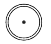
|
Solenoid \[\text{L}=\frac{{{\mu }_{0}}{{\text{N}}^{2}}\text{r}}{\ell }={{\mu }_{0}}{{\text{n}}^{2}}\text{A}\ell \] | 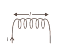
|
Toroid | 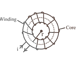
|
Square Coil \[\text{L}=\frac{2\sqrt{2}{{\mu }_{0}}{{\text{N}}^{2}}\text{a}}{\pi }\] | 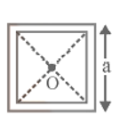
|
Triangular Coil \[\text{B}=\frac{{{\mu }_{0}}}{4\pi }\cdot \frac{18\text{Ni}}{\ell }\] \[\text{L}=\frac{\text{N}\left( \frac{{{\mu }_{0}}}{4\pi }\cdot \frac{18\text{Ni}}{\ell } \right)\times \left( \frac{\sqrt{3}}{4}{{\ell }^{2}} \right)}{\text{i}}\] | 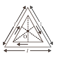
|
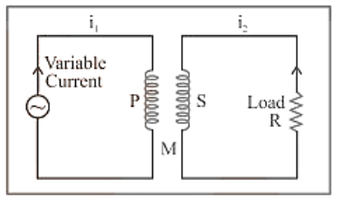
11.2 Mutual Induction -
Whenever the current passing through a coil or circuit changes, the magnetic flux linked with a neighbouring coil or circuit will also change. Hence an emf will be induced in the neighboring coil or circuit. This phenomenon is called 'mutual induction'.
(1) Coefficient of Mutual Induction :
Total flux linked with the secondary due to current in the primary is $\mathrm{N}_{2} \phi_{2}$ and $\mathrm{N}_{2} \phi_{2} \propto i 1 \Rightarrow N_{2} \phi_{2}=M i_{1}$ where $N_{1}-$ Number of turns in primary; $N_{2}$ - Number of turns in secondary; 2 - Flux linked with each turn of secondary; $i_{1}$ - Current flowing through primary; $M$-Coefficient of mutual induction or mutual inductance.
(2) According to Faraday's second law emf induces in secondary $\mathrm{e}_{2}=-\mathrm{N}_{2} \frac{\mathrm{d} \phi_{2}}{\mathrm{dt}} ; \mathrm{e}_{2}=-\mathrm{M} \frac{\mathrm{di}_{1}}{\mathrm{dt}}$
(3) If $\frac{\mathrm{di}_{1}}{\mathrm{dt}}=\frac{1 \mathrm{Amp}}{\mathrm{sec}}$ then $\left|\mathrm{e}_{2}\right|=\mathrm{M} .$ Hence coefficient of mutual induction is equal to the emf induced in the secondary coil when rate of change of current in primary coil is unity
(4) Units and dimensional formula of $M:$ Similar to self-inductance (L)
(5) Dependence of mutual inductance:
(i) Number of turns $\left(N_{1}, N_{2}\right)$ of both coils
(ii) Coefficient of self-inductances $\left(L_{1}, L_{2}\right)$ of both the coils
(iii) Area of cross-section of coils
(iv) Magnetic permeability of medium between the coils $\left(\mu_{r}\right)$ or nature of the material on which two coils are wound
(i) Distance between two coils (As $d$ increases so $M$ decreases)
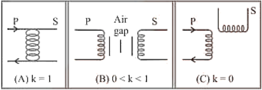
(ii) Coupling factor ' $K$ ' between primary and secondary coil.
(vi) Orientation between primary and secondary coil (for 90 orientation no flux relation $M=0$ )
(6) Relation between $M, L_{1}$ and $L_{2}:$ For two magnetically coupled coils $\mathrm{M}=\mathrm{K} \sqrt{\mathrm{L}_{1} \mathrm{~L}_{2}}$ where $\mathrm{k}$ - coefficient of coupling or coupling factor which is defined as; $\mathrm{K}=\frac{\text { Magnetic flux linked in secondary }}{\text { Magnetic flux linked in primary }}$ $0 \leq \mathrm{K} \leq 1$
(7) The various formulae for $M$:
Condition | Figure |
Two concentric coplanar circular coils \[\text{M}=\frac{\pi {{\mu }_{0}}{{\text{N}}_{1}}{{\text{N}}_{2}}{{\text{r}}^{2}}}{2\text{R}}\] | 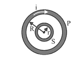
|
Two Solenoids \[\text{M}=\frac{{{\mu }_{0}}{{\text{N}}_{1}}{{\text{N}}_{2}}\text{A}}{\ell }\] | 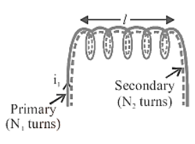
|
Two concentric coplaner square coils \[\text{M}=\frac{{{\mu }_{0}}2\sqrt{2}{{\text{N}}_{1}}{{\text{N}}_{2}}{{\ell }^{2}}}{\pi \text{L}}\] | 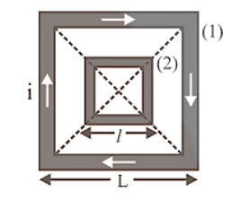
|
11.3. Combination of Inductance
(1) Series. If two coils of self-inductance $L_{1}$ and $L_{2}$ having mutual inductance are in series and are far from each other, so that the mutual induction between them is negligible, then net self-inductance $\mathrm{L}_{\mathrm{s}}=\mathrm{L}_{1}+\mathrm{L}_{2}$
When they are situated close to each other, then net inductance $\mathrm{L}_{\mathrm{s}}=\mathrm{L}_{1}+\mathrm{L}_{2} \pm 2 \mathrm{M}$
(2) Parallel if two coils of self-inductances $L_{1}$ and $L_{2}$ having mutual inductance are connected in parallel and are far from each other, then net inductance $\mathbf{L}$ is $\frac{1}{L_{p}}=\frac{1}{L_{1}}+\frac{1}{L_{2}} \Rightarrow L_{p}=\frac{L_{1} L_{2}}{L_{1}+L_{2}}$
When they are situated close to each other, then
$L_{p}=\frac{L_{1} L_{2}-M^{2}}{L_{1}+L_{2} \pm 2 M}$
Mutual induction is absent(k=0) | Mutual induction is present and favors self-induction of coils | Mutual induction is present and opposes self-induction of coils |
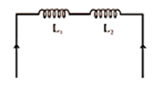
\[{{\mathrm{L}}_{\text{eq}}}={{\mathrm{L}}_{1}}+{{\mathbf{L}}_{2}}\] | 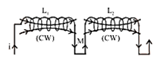
Current in same direction Winding nature same Their flux assist each other $\mathrm{L}_{\mathrm{m}}=\mathrm{L}_{1}+\mathrm{L}_{2}+2 \mathrm{M}$ | 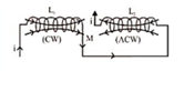
Current in opposite direction Opposite winding nature Their flux opposes each other \[{{\text{L}}_{\text{eq}}}={{\text{L}}_{1}}+{{\text{L}}_{2}}-2\text{M}\] |
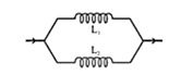
\[{{\text{L}}_{e\text{q}}}=\frac{{{\text{L}}_{1}}{{\text{L}}_{2}}}{{{\text{L}}_{\text{I}}}+{{\text{L}}_{2}}}\] | 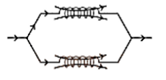
\[{{L}_{eq}}=\frac{{{L}_{1}}{{L}_{2}}-{{M}^{2}}}{{{L}_{1}}+{{L}_{2}}+2M}\] | 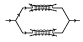
\[{{L}_{eq}}=\frac{{{L}_{1}}{{L}_{2}}-{{M}^{2}}}{{{L}_{1}}+{{L}_{2}}-2M}\] |
11.4. Growth and Decay of Current in lR Circuit
When a circuit with a pure inductor $L$ and a resistor $R$ in series with a battery and a key is closed, the current through the circuit climbs exponentially until it reaches a maximum value (steady-state). When a circuit is opened from its steady state, the current flowing through it diminishes exponentially.
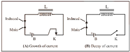
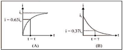
(1) The value of current at any instant of time t after closing the circuit (i.e. during the rising of current) is given by $i=i_{0}\left[1-e^{-\frac{k}{L}^{1}}\right] ;$ where $i_{0}=i_{\max }=\frac{E}{R}=$ steady state current.
(2) The value of current at any instant of time t after opening from the steady-state condition (i.e. during the decaying of current) is given by $i=i_{0} e^{-\frac{R}{L}}$
(3) Time constant $(\tau) \dot{i}$ It is given as $\tau=\frac{L}{R}$; It's unit is second. In other words, the time interval, during which the current in an inductive circuit rises to $63 \%$ of its maximum value at make, is defined as the time constant or it is the time interval, during which the current after opening an inductive circuit falls to $37 \%$ of its maximum value.
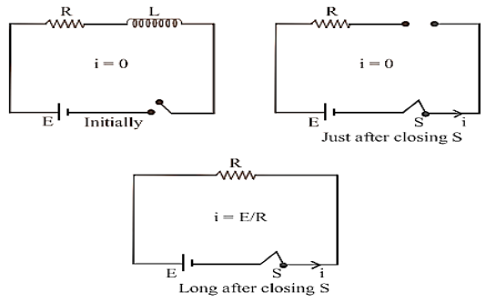
(4) Behaviour of inductor $i$ The current in the circuit grows exponentially with time from 0 to the maximum value $i\left(=\frac{E}{R}\right) .$ Just after closing the switch as $i=$ 0, inductor act as open circuit i.e. broken wires and long after the switch has been closed as $i=i_{0}$, the inductor act as a short circuit i.e. a simple connecting wire.
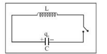
11.5. Lc Oscillation:
When a charged capacitor $C$ having an initial charge $q_{0}$ is discharged through an inductance $\mathrm{L}$, the charge and current in the circuit start oscillating simple harmonically. If the resistance of the circuit is zero, no energy is dissipated as heat. We also assume an idealized situation in which energy is not radiated away from the circuit. The total energy associated with the circuit is constant.
Frequency of oscillation is given by: $\omega=\frac{1}{\sqrt{\mathrm{LC}}} \frac{\mathrm{rad}}{\mathrm{sec}}$
$\mathrm{Or}=\frac{1}{2 \pi \sqrt{\mathrm{LC}}} \mathrm{Hz}$
The oscillation of the $L C$ circuit is an electromagnetic analogue to the mechanical oscillation of a block-spring system.
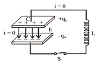
At t=0, the capacitor is ready to discharge. | (Image will be uploaded soon) At t=0 block is ready to move. |
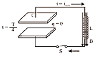
At $t=\dfrac {T}{4}$, the capacitor is fully discharged. i.e., charge q=0 and current is maximum. | (Image will be uploaded soon) At $t=\dfrac {T}{4}$, the block comes in its mean position i.e. x=0 and velocity of the block becomes maximum |
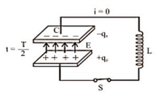
At $t=\dfrac {T}{2}$,the capacitor is again recharged with reverse polarity and i=0. | (Image will be uploaded soon) At $t=\dfrac {T}{2}$, the block reaches its extreme position on the other side and v=0. |
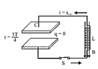
At $t=\dfrac {3T}{4}$, capacitor again discharged completely $i={i_{max}}$ | (Image will be uploaded soon) At $t=\dfrac {3T}{4}$, the block again reaches it's mean position and it's velocity becomes maximum. |
Tips and Tricks:
1. If a bar magnet moves towards a fixed conducting coil, then due to the flux changes an emf, current and charge are induced in the coil. If the speed of the magnet increases then the induced emf and induced current increase but the induced charge remains the same.
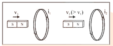
Induced parameter: $e_{1}$, $i_{1}$, $q_{1}$
$e_{2}\left(>e_{1}\right)$, $i_{2}\left(>i_{1}\right)$, $q_{2}\left(=q_{1}\right)$
2. Can ever electric lines of force be closed curves? Yes, when produced by a changing magnetic field.
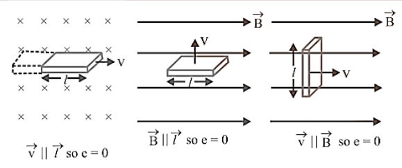
3. No flux cutting $\longrightarrow$ No EMI
4. Vector form of motional $\mathrm{emf}: \mathrm{e}=(\overrightarrow{\mathrm{v}} \times \overrightarrow{\mathrm{B}}) \vec{\ell}$
5. In motional $\operatorname{smf} \vec{v}, \vec{B}$ and $\vec{l}$ are three vectors. If any two vector are parallel - No flux cutting.
6. A piece of metal and a piece of non-metal are dropped from the same height near the surface of the earth. The non-metallic piece will reach the ground first because there will be no induced current in it.
7. If an aeroplane is landing down or taking off and its wings are in the east-west direction, then the potential difference or emf will be induced across the wings. If an aeroplane is landing down or taking off and its wings are in the north-south direction, then no potential difference or emf will be induced.
8. When a conducting rod moving horizontally on the equator of earth no emf induces because there is no vertical component of the earth's magnetic field. But at poles, BV is maximum so maximum flux cutting hence emf induces.
9. When a conducting rod falls freely in earth's magnetic field such that it's length lies along the East-West direction then induced emf continuously increases w.r.t. time and induced current flows from West - East. $10.1$ henry $y=109 \mathrm{emu}$ of inductance or $109 \mathrm{ab}$ - henry.
11. Inductance at the ends of a solenoid is half of it's the inductance at the centre $\left(\mathrm{L}_{\text {end }}=\frac{1}{2} \mathrm{~L}_{\text {conte }}\right)$
12. A thin, long wire composed of a high-resistivity material acts primarily as a resistance. It does, however, contain some inductance and capacitance. As a result, obtaining a pure resistor is challenging. Pure capacitors and inductors are similarly difficult to come by.
13. A resistive circuit with no capacitive or inductive elements contains some inductance because of the intrinsic presence of self-inductance in all electrical circuits.
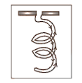
Self-inductance can be reduced by doubling back the coil on itself, as in the coils of a resistance box.
14. It is not possible to have mutual inductance without self-inductance but it may or may not be possible self-inductance without mutual inductance.
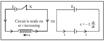
15. If main current through a coil increases $(i \uparrow) s o \frac{d i}{d t}$ will be positive (+ve), hence induced emf e will be negative (i.e. opposite $\mathrm{gmf}$ ) $=E_{\text {net }}=E-e$
16. Due to the high inductance of the circuit, a high temporarily induced $\mathrm{emf}$ is sometimes produced when the key is suddenly opened, resulting in sparking at the key position. A capacitor is put across the key to prevent sparking.
17. Due to the high inductance of the circuit, a high temporarily induced $\mathrm{emf}$ is sometimes produced when the key is suddenly opened, resulting in sparking at the key position. A capacitor is put across the key to prevent sparking.
18. Resistance can exist with or without inductance, but inductance cannot exist without resistance.
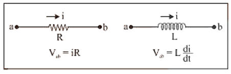
19. An inductor's circuit behavior differs significantly from that of a resistor. while a resistor opposes the current i, an inductor opposes the change $\frac{d i}{d t}$ in the circuit.
20. In RL-circuit with dc source the time taken by the current to reach half of the maximum value is called half life time and it is given by
$\mathrm{T}=0.693 \frac{\mathrm{L}}{\mathrm{R}}$
21. The dc motor is a versatile energy conversion device that can be used in a variety of applications. It can handle loads that require a lot of starting torque, as well as accelerating and decelerating torque.
22. Ohm's law can be utilized when a source of emf is linked across the two ends of the primary winding or the two ends of the secondary winding alone. However, because the primary and secondary windings are not electrically coupled, ohm's law should not be applied to the transformer as a whole.
23. Even when the transformer's secondary circuit is open, it pulls a current termed no load primary current to supply no load Cu and iron losses.
24. Transformer has highest possible efficiency out of all the electrical machines.
Important Electromagnetic Induction Related Links
Chapter-wise Links for Class 12 Physics Notes PDF FREE Download
Related Study Materials Links for Class 12 Physics
Along with this, students can also download additional study materials provided by Vedantu for Physics Class 12–
Importance of Chapter 6 Electromagnetic Induction Class 12 Notes
Here’s the importance of Chapter 6 Electromagnetic Induction Class 12 Notes in pointers:
Foundation for Key Concepts: Helps in understanding how electric currents are produced through changing magnetic fields.
Important Laws: Covers essential principles like Faraday’s laws, Lenz’s law, and self-induction, which are core to electromagnetism.
Relevance for Board Exams: The concepts are critical for Class 12 board exams, ensuring a strong grasp of electromagnetism topics.
Competitive Exam Preparation: Vital for entrance exams like JEE and NEET, where questions on electromagnetic induction are common.
Simplified Explanations: The notes break down complex topics into simple explanations, aiding easy understanding.
Focused Revision: Provides key formulas and solved examples for efficient last-minute revision.
Important Formulas of Class 12 Chapter 6 Physics You Shouldn’t Miss!
Here are the important formulas for Class 12 Physics Chapter 1: Electromagnetic Induction that you shouldn’t miss:
1. Faraday’s Law of Electromagnetic Induction:
$ \mathcal{E} = -\frac{d\Phi}{dt} $
(Where $ \mathcal{E} $ is the induced emf, and $ \Phi $ is the magnetic flux)
2. Magnetic Flux:
$ \Phi = B \cdot A \cdot \cos\theta $
(Where $ B $ is the magnetic field, $ A $ is the area, and $ \theta $ is the angle between the magnetic field and the area vector)
3. Lenz’s Law:
The direction of the induced current opposes the change in magnetic flux that produces it.
4. Induced EMF in a Moving Conductor:
$ \mathcal{E} = B \cdot l \cdot v \cdot \sin\theta $
(Where $ B $ is the magnetic field, $ l $ is the length of the conductor, $ v $ is the velocity, and $ \theta $ is the angle between $ v $ and $ B $)
5. Self-Inductance (L):
$ \mathcal{E} = -L \frac{di}{dt} $
(Where $ \mathcal{E} $ is the induced emf and $ \frac{di}{dt} $ is the rate of change of current)
6. Energy Stored in an Inductor:
$ U = \frac{1}{2} L I^2 $
(Where $ U $ is the energy, $ L $ is the inductance, and $ I $ is the current)
7. Mutual Inductance (M):
$ \mathcal{E}_2 = -M \frac{di_1}{dt} $
(Where $ \mathcal{E}_2 $ is the emf induced in the second coil due to the change in current in the first coil)
8. Induced EMF in a Rotating Coil:
$ \mathcal{E} = N B A \omega \sin(\omega t) $
(Where $ N $ is the number of turns, $ B $ is the magnetic field, $ A $ is the area, and $ \omega $ is the angular velocity)
Tips For Learning the Class 12 Physics Chapter 6 Electromagnetic Induction
Here are some helpful tips for learning Class 12 Physics Chapter 6 Electromagnetic Induction:
Understand Basic Concepts First: Start by revising the basics of magnetism and electricity to build a strong foundation for understanding electromagnetic induction.
Focus on Faraday’s and Lenz’s Laws: These two laws are central to the chapter. Practice applying them to different scenarios to get comfortable with induced EMF and its direction.
Learn and Practice Important Formulas: Make sure to memorize key formulas like $E = -\frac{d\Phi}{dt}$, mutual inductance, and energy stored in an inductor. Practice problems to apply these formulas correctly.
Visualise Concepts with Diagrams: Use diagrams and flowcharts to understand the working of devices like generators, transformers, and inductors. Visualisation helps in remembering processes better.
Solve NCERT Problems: Work through the NCERT textbook exercises and examples to strengthen your understanding and problem-solving skills.
Use Real-Life Examples: Relate the concepts to real-world applications like power generation, transformers, and electric motors to better grasp the practical use of electromagnetic induction.
Revise Regularly: Make summary notes of key points and revise them frequently. Regular revision will help in retaining the complex concepts of this chapter.
Practice Derivations: The derivations of key formulas are often asked in exams. Practice them step by step to ensure you can reproduce them during the exam.
Conclusion
Chapter 6 Electromagnetic Induction in Class 12 Physics is fundamental in understanding how electric currents are generated through magnetic fields, with practical applications in real-life devices like generators and transformers. Mastering this chapter is crucial for board exams and competitive exams like JEE and NEET. By studying the key laws, practising important formulas, and applying these concepts to problem-solving, students can strengthen their grasp of electromagnetic induction. Vedantu’s detailed notes and resources further aid in simplifying these concepts, ensuring efficient revision and confident exam preparation.
FAQs on CBSE Notes Class 12 Physics Chapter 6 - Electromagnetic Induction - 2026-27
1. What is the core principle of electromagnetic induction (EMI) in simple terms?
The core principle is that a changing magnetic field creates an electric current in a nearby conductor. Essentially, if the magnetic flux (the amount of magnetic field passing through an area) linked with a closed-loop changes for any reason, an electromotive force (EMF) and hence a current are induced in the loop, as per the CBSE 2026-27 syllabus.
2. How can I quickly summarize Faraday's Laws and Lenz's Law for revision?
For a quick revision, remember these key points:
- Faraday's First Law: Whenever the magnetic flux linked with a circuit changes, an EMF is induced. This EMF lasts only as long as the flux is changing.
- Faraday's Second Law: The magnitude of the induced EMF is directly proportional to the rate of change of the magnetic flux (ε = -dΦ/dt).
- Lenz's Law: This law gives the direction of the induced current. It states that the direction of the induced current will be such that it opposes the change in magnetic flux that produced it. The negative sign in Faraday's formula represents Lenz's Law.
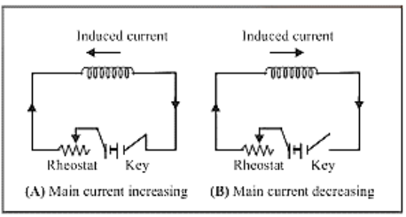
3. Why is induced EMF often called 'back EMF', and what does this imply?
Induced EMF is called 'back EMF' because it always opposes the very change in current that creates it, as stated by Lenz's Law. If the main current in a circuit is increasing, the back EMF will act against it to slow the increase. If the main current is decreasing, the back EMF will act in the same direction to try and sustain it. This property is the basis of inductance.
4. If a conductor is stationary in a uniform magnetic field, why is there no induced EMF?
No EMF is induced because there is no change in the magnetic flux linked with the coil. For electromagnetic induction to occur, the magnetic flux must change over time. This can happen if the magnet moves, the coil moves, or the magnetic field strength itself varies, but not when both are stationary in a uniform field.
5. What is the main difference between self-inductance and mutual-inductance?
The main difference lies in which circuit's changing current induces the EMF:
- Self-Inductance (L): This is the property of a single coil to induce an EMF in itself due to a change in the current flowing through it. It opposes the change in its own current.
- Mutual-Inductance (M): This is the property of two nearby coils. An EMF is induced in one coil (the secondary coil) due to a change in current in the other coil (the primary coil). It describes how the flux from one coil links with another.
6. What are eddy currents, and how are they applied in technologies like magnetic brakes?
Eddy currents are loops of electric current induced within a bulk piece of a conductor by a changing magnetic field. They flow in closed loops in planes perpendicular to the magnetic field. A key application is in the magnetic braking systems of trains, where strong electromagnets are activated. This induces large eddy currents in the rails, which create a magnetic field that opposes the motion of the train, resulting in smooth braking without physical contact.
7. When a bar magnet falls through a metal ring, why is its acceleration less than 'g'?
This happens due to Lenz's Law. As the magnet falls towards the ring, the magnetic flux through the ring increases. To oppose this increase, the ring induces a current that creates a magnetic field with a polarity that repels the falling magnet. This upward repulsive force acts against gravity, causing the magnet's net downward acceleration to be less than the acceleration due to gravity (g).
8. What is motional EMF, and what is the key formula to remember for a straight conductor?
Motional EMF is the electromotive force induced in a conductor moving through a stationary magnetic field. When a conductor moves, the free charges inside it also move and experience a magnetic force, which pushes them to one end, creating a potential difference. For a straight conductor of length 'l' moving with velocity 'v' perpendicular to a magnetic field 'B', the key formula to remember is ε = Bvl.
9. How does the principle of EMI apply to an AC generator?
An AC generator works entirely on the principle of electromagnetic induction. A rectangular coil (armature) is rotated mechanically in a uniform magnetic field. As the coil rotates, the angle between the magnetic field and the coil's area vector continuously changes. This causes a continuous change in the magnetic flux linked with the coil. According to Faraday's law, this changing flux induces a periodically varying (sinusoidal) EMF and an alternating current (AC).
10. What key factors determine the self-inductance of a solenoid?
The self-inductance (L) of a solenoid primarily depends on its physical characteristics:
- Number of Turns (N): Inductance is proportional to the square of the number of turns (L ∝ N²).
- Area of Cross-section (A): A larger area means more flux linkage, so L ∝ A.
- Length of the Solenoid (l): Inductance is inversely proportional to the length (L ∝ 1/l).
- Permeability of the Core Material (μ): Inserting a core material with high magnetic permeability (like soft iron) significantly increases the inductance.