


Class 12 Physics Chapter 10 Summary Notes PDF Download
Vedantu’s revision notes for Class 12 Physics Chapter 10, Wave Optics explores the light waves, focusing on interference, diffraction, and polarisation. According to the CBSE Class 12 Physics Syllabus, understanding these concepts is important for learning wave behaviour and optical phenomena.
 Table of Content
In this chapter, we'll break down complex ideas into simple explanations, using clear examples and diagrams. Our revision notes are designed to help you grasp the key concepts effectively, making your exam preparation smoother and more efficient. Dive into the details of wave optics. With Class 12 Physics Revision Notes, students can easily revise and gain a solid understanding of the chapter for better performance in exams.


1. Wave Front:
A light source is a point which emits disturbance in all directions. In a homogeneous medium, the disturbance reaches all those particles of the medium in phase, which are located at the same distance from the source of light and hence at all the time, every particle must be vibrating in phase with each other. The locus of all the particles of medium, which at any instant are vibrating in the same phase, is called the wave front.
Depending upon the shape of the source of light, wave front can be the following types:
1. Spherical wavefront
2. Cylindrical wavefront
1.1. Spherical Wave Front:
A point source of light produces a spherical wave front. This is because the locus of every points, which are equidistant from the point source, is a sphere figure (a).
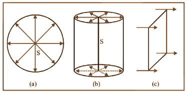
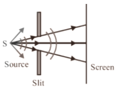
1.2. Cylindrical Wave Front:
If the light source is linear (such as a slit), it produces a cylindrical wave front. Here, every points, which are equidistant from the linear source, lie on the surface of a cylinder figure (b).
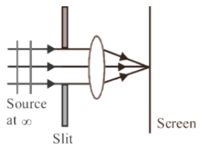
1.3. Plane Wave Front:
A wave front will appear plane if it is a small part of a spherical or a cylindrical wave front I originating from a distant source. So it is called a plane wave front figure (c).
1.4. Ray of Light:
The path along which light travels is known as a ray of light. If we draw an arrow normal to the wave front and which points in the direction of propagation of disturbance represents a ray of light. In a ray diagram, thick arrows represent the rays of light.
It is also called as the wave normal because the ray of light is normal to the wave front.
Key Points:
If we take any two points on a wave front, the phase difference between them will be zero.
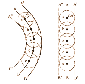
2. Huygens’s Principle:
Huygens’s principle is a geometrical construction, which can be used to obtain new position of a wave front at a later time from its given position at any instant. Or we can quote that this principle gives a method gives an idea about how light spreads out in the medium.
It is developed on the following assumptions:
1. All the points on a given or primary wave front acts as a source of secondary wavelets, which sends out disturbance in all directions in a similar manner as the primary light source.
2. The new position of the wave front at any instant (called secondary wave front) is the envelope of the secondary wavelets at that instant.
These two assumptions are known as Huygens principle or Huygens’ construction.
Key Point:
Huygens principle is simply a geometrical construction to find the position of wave front at a later time.
3. Principle of Superposition:
If two or more than two waves superimpose each other at a common particle of the medium then the resultant displacement \[\left( \text{y} \right)\] of the particle is equal to the vector sum of the displacements (\[{{\text{y}}_{\text{1}}}\] and \[~{{\text{y}}_{\text{2}}}\] ) produced by individual waves .i.e $\overrightarrow{\text{y}}\text{=}\overrightarrow{{{\text{y}}_{\text{1}}}}\text{+}\overrightarrow{{{\text{y}}_{\text{2}}}}$
Refraction of a plane wave:
Refraction of a plane wave refers to the bending of light waves as they pass from one medium into another with a different density. In simple terms, when light travels from air into water or glass, its speed changes, causing the light to bend. This bending occurs at the boundary between the two media.
Key Points to Remember:
Snell's Law: It describes how the angle of incidence and angle of refraction are related to the speeds of light in the two media.
Formula: $\frac{\sin \theta_1}{\sin \theta_2} = \frac{v_1}{v_2} = \frac{n_2}{n_1}$, where $\theta_1$ and $\theta_2$ are the angles of incidence and refraction, $v_1$ and $v_2$ are the speeds of light in the two media, and $n_1$ and$n_2$ are the refractive indices of the media.
Understanding refraction helps explain phenomena like why a straw looks bent when placed in a glass of water.
Refraction at a rarer medium: It refers to the bending of light when it passes from a denser medium (like water or glass) to a rarer medium (like air).
When light moves from a denser medium to a rarer medium, it speeds up and bends away from the normal line (an imaginary line perpendicular to the surface). This bending occurs because light travels more slowly in denser materials and faster in rarer ones. The degree of bending depends on the angle at which the light enters the new medium and the refractive indices of the two media. This principle is crucial in understanding how lenses and other optical devices work.
Reflection of a Plane Wave by a Plane Surface:
The reflection of a plane wave by a plane surface refers to how light waves bounce off a flat surface. Here's a simple breakdown:
Incident and Reflected Waves: When a plane wave (a flat, uniform wave) strikes a plane surface, it is called the incident wave. The wave that bounces off the surface is called the reflected wave.
Law of Reflection: The angle at which the incident wave hits the surface (angle of incidence) is equal to the angle at which the wave reflects off the surface (angle of reflection). This is known as the law of reflection.
Normal Line: The angles are measured with respect to an imaginary line perpendicular to the surface, called the normal line.
Wavefronts and Rays: The wavefronts (lines of constant phase) of the incident wave are parallel to those of the reflected wave, and the direction of the reflected wave is determined by the angles of incidence and reflection.
Understanding this concept helps explain how mirrors work and how we see reflections in everyday life.
3.1. Phase/Phase difference/Path difference/Time difference
i. Phase: Phase is defined as the argument of sine or cosine in the expression for displacement of a wave. For displacement $\text{y = asin }\!\!\omega\!\!\text{ t}$ ; term $\text{ }\!\!\omega\!\!\text{ t =}$ phase or instantaneous phase.
ii. Phase Difference $\left( \phi \right)$: Phase difference is the difference between the phases of two waves at a point. i.e. if ${{\text{y}}_{\text{1}}}\text{=}{{\text{a}}_{\text{1}}}\text{sin }\!\!\omega\!\!\text{ t}$ and ${{\text{y}}_{\text{2}}}\text{=}{{\text{a}}_{\text{2}}}\text{sin}\left( \text{ }\!\!\omega\!\!\text{ t+}\phi \right)$ so phase difference $=\phi $
iii. Path Difference $\left( \Delta \right)$: Path difference between the waves at that point is the difference in path lengths of two waves meeting at a point. Also $\text{ }\!\!\Delta\!\!\text{ =}\frac{\text{ }\!\!\lambda\!\!\text{ }}{\text{2 }\!\!\pi\!\!\text{ }}\text{ }\!\!\times\!\!\text{ }\phi $.
iv. Time Difference (T.D): Time difference between the waves meeting at a point is given by T.D $\text{= }\frac{\text{T}}{\text{2 }\!\!\pi\!\!\text{ }}\times \phi $
3.2. Resultant Amplitude and Intensity
If we have two waves ${{\text{y}}_{\text{1}}}\text{= }{{\text{a}}_{\text{1}}}\text{sin }\!\!\omega\!\!\text{ t}$ and ${{\text{y}}_{\text{2}}}\text{= }{{\text{a}}_{\text{2}}}\text{sin}\left( \text{ }\!\!\omega\!\!\text{ t+}\phi \right)$ where ${{\text{a}}_{\text{1}}}\text{,}{{\text{a}}_{\text{2}}}\text{=}$ Individual amplitudes, $\phi =$ Phase difference between the waves at an instant when they are meeting a point. ${{\text{I}}_{\text{1}}}\text{,}{{\text{I}}_{\text{2}}}\text{=}$Intensities of Individual waves.
Resultant Intensity:
As we know intensity $\text{ }\!\!\alpha\!\!\text{ }{{\left( \text{Amplitude} \right)}^{\text{2}}}$ $\Rightarrow {{\text{I}}_{\text{1}}}\text{-k}{{\text{a}}_{\text{1}}}^{\text{2}}\text{,}{{\text{I}}_{\text{2}}}\text{-k}{{\text{a}}_{\text{2}}}^{\text{2}}\text{ and I=k}{{\text{A}}^{2}}(k$ is a proportionality constant) . Hence from the formula of resultant amplitude, we get the following formula of resultant intensity
$\text{I-}{{\text{I}}_{\text{1}}}\text{+}{{\text{I}}_{\text{2}}}\text{+2}\sqrt{{{\text{I}}_{\text{1}}}{{\text{I}}_{\text{2}}}}\text{cos}\phi $
The term $\text{2}\sqrt{{{\text{I}}_{\text{1}}}{{\text{I}}_{\text{2}}}}\text{cos}\phi $ is called interference term. For incoherent interference this term is zero so resultant intensity $\text{I=}{{\text{I}}_{\text{1}}}\text{+}{{\text{I}}_{\text{2}}}$
3.3. Coherent Sources:
Coherent sources are the sources of light which emits continuous light waves with same wavelength, frequency and in phase or having a constant phase difference.
4. Interference of Light:
If intensity of light at some points is maximum while at some other point intensity is minimum due to the simultaneous superposition of two waves of exactly same frequency (coming from two coherent sources) travels in a medium and in the same direction, this phenomenon is called Interference of light.
4.1. Types of Interference:
4.2. Resultant Intensity Due to Two Identical Waves:
The resultant intensity for two coherent sources is given by
$\text{I=}{{\text{I}}_{\text{1}}}\text{+}{{\text{I}}_{\text{2}}}\text{+2}{{\sqrt{{{\text{I}}_{\text{1}}}\text{I}}}_{\text{2}}}\cos \phi $
For identical source ${{\text{I}}_{\text{1}}}\text{=}{{\text{I}}_{\text{2}}}\text{=}{{\text{I}}_{\text{0}}}$
$\Rightarrow \text{I=}{{\text{I}}_{\text{0}}}\text{+}{{\text{I}}_{\text{0}}}\text{+2}\sqrt{{{\text{I}}_{\text{0}}}{{\text{I}}_{\text{0}}}}\cos \phi =\text{4}{{\text{I}}_{\text{0}}}{{\cos }^{2}}\frac{\phi }{2}$
$\left[ 1+\cos \theta =2{{\cos }^{2}}\frac{\theta }{2} \right]$
Note:
Redistribution of energy takes place in the form of maxima and minima in interference
Average Intensity: ${{\text{I}}_{\text{av}}}\text{=}\frac{{{\text{I}}_{\text{max}}}\text{+}{{\text{I}}_{\text{min}}}}{\text{2}}\text{=}{{\text{I}}_{\text{1}}}\text{+}{{\text{I}}_{\text{2}}}\text{=}{{\text{a}}_{\text{1}}}^{\text{2}}\text{+}{{\text{a}}_{\text{2}}}^{\text{2}}$
Ratio of Maximum and Minimum Intensities:
$\frac{{{I}_{\max }}}{{{I}_{\min }}}={{\left( \frac{\sqrt{{{I}_{1}}}+\sqrt{{{I}_{2}}}}{\sqrt{{{I}_{1}}}-\sqrt{{{I}_{2}}}} \right)}^{2}}{{\left( \frac{\sqrt{{{I}_{1}}/{{I}_{2}}}+1}{\sqrt{{{I}_{1}}/{{I}_{2}}}-1} \right)}^{2}}={{\left( \frac{{{a}_{1}}+{{a}_{2}}}{{{a}_{1}}-{{a}_{2}}} \right)}^{2}}={{\left( \frac{{{a}_{1}}/{{a}_{2}}+1}{{{a}_{1}}/{{a}_{2}}-1} \right)}^{2}}$
Also $\sqrt{\frac{{{I}_{1}}}{{{I}_{2}}}}=\frac{{{a}_{1}}}{{{a}_{2}}}=\left( \frac{\sqrt{\frac{{{I}_{\max }}}{{{I}_{\min }}}}+1}{\sqrt{\frac{{{I}_{\max }}}{{{I}_{\min }}}}-1} \right)$
If two waves having equal intensity $\left( {{\text{I}}_{\text{1}}}\text{=}{{\text{I}}_{\text{2}}}\text{=}{{\text{I}}_{\text{0}}} \right)$ meets at two locations $\text{P}$ and $\text{Q}$ with path difference ${{\Delta }_{1}}$ and ${{\Delta }_{2}}$ respectively then the ratio of resultant intensity at point
$\text{P}$ and $\text{Q}$ will be $\frac{{{I}_{p}}}{{{I}_{Q}}}=\frac{{{\cos }^{2}}\frac{{{\phi }_{1}}}{2}}{{{\cos }^{2}}\frac{{{\phi }_{2}}}{2}}=\frac{{{\cos }^{2}}\left( \frac{\pi {{\Delta }_{1}}}{\lambda } \right)}{{{\cos }^{2}}\left( \frac{\pi {{\Delta }_{2}}}{\lambda } \right)}$
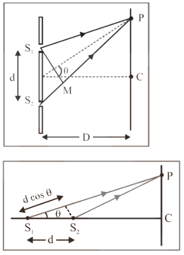
5. Young’s Double Slit Experiment (YDSE):
An interference pattern is obtained on the screen when monochromatic light (single wavelength) falls on two narrow slits ${{\text{S}}_{1}}\text{ and }{{\text{S}}_{2}}$ which are very close together acts as two coherent sources, and when waves coming from these two sources superimposes on each other. Alternate bright and dark bands obtained on the screen in this experiment. These bands are called Fringes.
$d=$ Distance between slits.
$D=$ Distance between slits and screen
$\lambda =$ Wavelength of monochromatic light emitted from source.
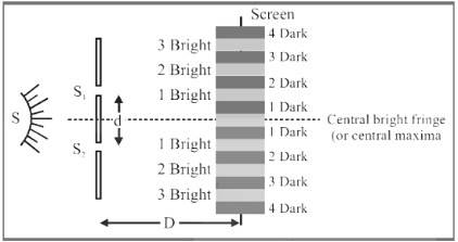
1. At the central position $\phi ={{0}^{o}}\text{ or }\Delta \text{=0}$. So, the Central fringe will always be bright.
2. The fringe pattern formed by a slit will be brighter than that due to a point.
3. The minima will not be completely dark if the slit widths are unequal. So, uniform illumination occurs for a very large width.
4. No interference pattern is observed on the screen if one slit is illuminated with red light and the other is illuminated with blue light.
5. The central fringe will be dark instead of bright if the two coherent sources consist of object and its reflected image.
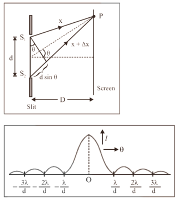
5.1. Path Difference:
Path difference between the interfering waves meeting at a point $P$ on the screen is given by $\text{x=}\frac{\text{yd}}{\text{D}}\text{=d}\sin \theta $ where $x$ is the position of point $P$ from central maxima.
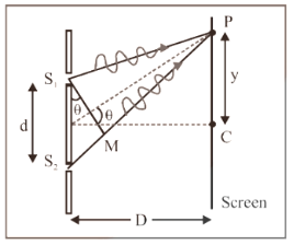
For maxima at$P$: $\text{x = n }\!\!\lambda\!\!\text{ }$
Where $n=0,\pm 1,\pm 2,...$
And for minima at$P$: $x=\frac{\left( 2n-1 \right)\lambda }{2}$
Where $n=0,\pm 1,\pm 2,...$
Note:
If the slits are horizontal path difference is $d\cos \theta $,so as $\theta $ increases,$x$ decreases. But if the slits are vertical, the path difference $\left( x \right)$is $d\sin \theta $, so as $\theta $ increases,$\Delta $ also increases.
5.2. More About Fringes:
(i) Every fringes will have equal width. Width of one fringe is $\text{ }\!\!\beta\!\!\text{ = }\frac{\text{ }\!\!\lambda\!\!\text{ D}}{\text{d}}$ and angular fringe width $\text{ }\!\!\theta\!\!\text{ = }\frac{\text{ }\!\!\lambda\!\!\text{ }}{\text{d}}$
(ii) If the YDSE setup is taken in one medium then changes into another, so $\beta $ changes. E.g. in water ${{\lambda }_{w}}=\frac{{{\lambda }_{a}}}{{{\mu }_{w}}}\Rightarrow {{\beta }_{w}}=\frac{{{\beta }_{a}}}{{{\mu }_{w}}}=\frac{3}{4}{{\beta }_{a}}$
(iii) Fringe width $\text{ }\!\!\beta\!\!\text{ }\propto \frac{\text{1}}{\text{d}}$ i.e if separation between the sources increases, $\beta $ decreases.
(iv) Position of ${{n}^{th}}$ bright fringe from central maxima ${{x}_{n}}=\frac{n\lambda D}{d}=n\beta ;n=0,1,2,..$
(v) Position of ${{n}^{th}}$dark fringe from central maxima ${{x}_{n}}=\frac{\left( 2n-1 \right)\lambda D}{2d}=\frac{\left( 2n-1 \right)\beta }{2};n=1,2,3,..$
(vi) In YDSE, if ${{n}_{1}}$ fringes are visible in a field of view with light of wavelength ${{\lambda }_{1}}$ , while ${{n}_{2}}$ with light of wavelength ${{\lambda }_{2}}$ in the same field, then ${{\text{n}}_{\text{1}}}{{\text{ }\!\!\lambda\!\!\text{ }}_{\text{1}}}\text{=}{{\text{n}}_{\text{2}}}{{\text{ }\!\!\lambda\!\!\text{ }}_{\text{2}}}$
5.3. Shifting of Fringe Pattern in YDSE:
The fringe pattern will get shifted if a transparent thin film of mica or glass is placed in the path of one of the waves. If this film is placed in the path of upper wave, the pattern shifts upward and if the film is placed in the path of lower wave, the pattern will shift downward.
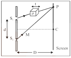
Fringe shift $\text{= }\frac{\text{D}}{\text{d}}\left( \text{ }\!\!\mu\!\!\text{ -1} \right)\text{t = }\frac{\text{ }\!\!\beta\!\!\text{ }}{\text{ }\!\!\lambda\!\!\text{ }}\left( \text{ }\!\!\mu\!\!\text{ -1} \right)\text{t}$
$\Rightarrow $ Additional path difference $=\left( \mu -1 \right)t$
$\Rightarrow $If the shift is equivalent to $\text{n}$fringes, then $\text{n=}\frac{\left( \text{ }\!\!\mu\!\!\text{ -1} \right)\text{t}}{\text{ }\!\!\lambda\!\!\text{ }}$ or $\text{t=}\frac{\text{n }\!\!\lambda\!\!\text{ }}{\left( \text{ }\!\!\mu\!\!\text{ -1} \right)}$
$\Rightarrow $Fringe shift is independent of the order of fringe (i.e shift of zero order maxima = shift of ${{\text{n}}^{\text{th}}}$ order maxima)
$\Rightarrow $Also, the shift is independent of wavelength.
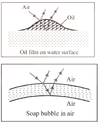
6. Illustrations of Interference
Interference effects are commonly observed in thin films when their thickness is comparable to wavelength of incident light (If it is too thin as compared to wavelength of light it appears dark and if it’s too thick, this will return in uniform illumination of film). Thin layer of oil on water surface and soap bubbles shows various colours in white light due to interference of waves reflected from the two surfaces of the film.
Thin Prisms:
It is a small optical device made from a transparent material like glass or plastic. It is used to separate light into its different colours, creating a spectrum.
Here’s a simple breakdown:
Structure: A thin prism has a small angle at its apex (the point where the two sides meet), making it thin compared to its other dimensions.
Function: When white light passes through the prism, it bends (or refracts) at different angles for different colours. This separation of colours occurs because each colour bends by a different amount due to its wavelength.
Dispersion: The phenomenon of separating light into its component colours is called dispersion. The result is a rainbow of colours, ranging from red to violet.
A thin prism helps us understand how light behaves when it interacts with different materials, which is crucial in optics.
7. Doppler’s Effect in Light:
The phenomenon due to relative motion between the source of light and the observer which causes apparent change in frequency (or wavelength) of the light is called Doppler’s effect.
According to special theory of relativity,
$\frac{\text{v }\!\!'\!\!\text{ }}{\text{v}}\text{=}\frac{\text{1 }\!\!\pm\!\!\text{ v/c}}{\sqrt{\text{1-}{{\text{v}}^{\text{2}}}\text{/}{{\text{c}}^{\text{2}}}}}$
If $v=$actual frequency, $v'=$ apparent frequency,$v=$ speed of source with respect to stationary observer, $c=$ speed of light.
8. Diffraction of Light:
The phenomenon of light bending around the corners of an obstacle/aperture whose size is comparable to the size of the wavelength of light.
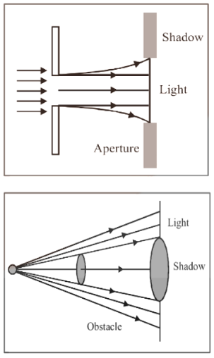
8.1. Types of Diffraction:
The diffraction phenomenon of light is divided into two types
Types of diffraction Phenomenon:
8.2. Diffraction of Light at a Single Slit:
In case of diffraction at a single slit, we get a central bright band with alternate bright (maxima) and dark (minima) bands of decreasing intensity as shown
(i) Width of central maxima ${{\text{ }\!\!\beta\!\!\text{ }}_{\text{o}}}\text{=}\frac{\text{2 }\!\!\lambda\!\!\text{ D}}{\text{d}}$ and angular width $\text{=}\frac{\text{2 }\!\!\lambda\!\!\text{ }}{\text{d}}$
(ii) The path difference between the waves from the two ends of the aperture is given by $\text{ }\!\!\Delta\!\!\text{ = n }\!\!\lambda\!\!\text{ }$ ; where $\text{n = 1,2,3,}...\text{i}\text{.e}\text{. dsin }\!\!\theta\!\!\text{ = n }\!\!\lambda\!\!\text{ }$ as the minima occurs at a point on either side of the central maxima.
$\Rightarrow \text{sin }\!\!\theta\!\!\text{ = }\frac{\text{n }\!\!\lambda\!\!\text{ }}{\text{d}}$
(iii) The secondary maxima occurs, where the path difference between the waves from the two ends of the aperture is given by $\text{ }\!\!\Delta\!\!\text{ =}\left( \text{2n+1} \right)\frac{\text{ }\!\!\lambda\!\!\text{ }}{\text{2}}$ ;
where,
$\text{n=1,2,3,}...\text{i}\text{.e}\text{. dsin }\!\!\theta\!\!\text{ =}\left( \text{2n+1} \right)\frac{\text{ }\!\!\lambda\!\!\text{ }}{\text{2}}\Rightarrow \text{sin }\!\!\theta\!\!\text{ = }\frac{\left( \text{2n+1} \right)\text{ }\!\!\lambda\!\!\text{ }}{\text{2d}}$
8.3. Comparison Between Interference and Diffraction:
8.4. Diffraction and Optical Instruments:
Objective lens of instrument like telescope or microscope etc. acts like a circular aperture. By diffraction of light at the circular aperture, a converging lens doesn’t form a point image of an object rather it produces a brighter disc surrounded by alternate dark and bright concentric rings known as Airy disc.
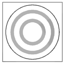
The angular half width of Airy disc$\text{= }\!\!\theta\!\!\text{ =}\frac{\text{1}\text{.22 }\!\!\lambda\!\!\text{ }}{\text{D}}$ (where $D=$ aperture of lens)
The lateral width of the image $=f\theta $ (where $f=$ focal length of the lens)
Note:
Diffraction of light limits the ability of optical instruments to form clear images of objects when they are close to each other.
9. Polarisation of Light:
Light travel as transverse EM waves. While comparing to magnitude of magnetic field, the magnitude of electric field is much larger. We generally describe light as electric field oscillations.
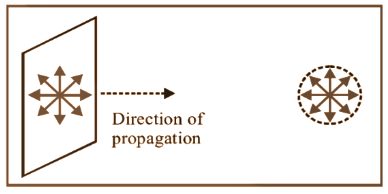
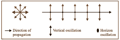
9.1. Unpolarized Light:
Light with electric field oscillations in every directions in the plane perpendicular to the propagation of it is called Unpolarised light. The oscillation of light is divided into horizontal and vertical components.
9.2. Polarised Light:
Polarized or plane polarized light is the light with oscillations only in one plane is.
Plane of oscillation is the plane in which oscillation occurs in the polarized light.
Plane of polarization is the plane perpendicular to the plane of oscillation.
By transmitting through certain crystals such as tourmaline or Polaroid light can be polarized.
9.3. Polaroid:
The device used to produce the plane polarised light is known as a Polaroid. It is based on the principle of selective absorption. Also, it is more effective than the tourmaline crystal.
It can also be described as a thin film of ultramicroscopic crystals of quinine iodo sulphate which has its optic axis parallel to each other.
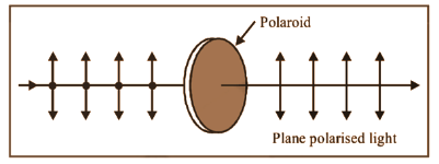
(i) A Polaroid only allows light oscillations which are parallel to the transmission axis to pass through them.
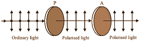
(ii) Polarizer is the crystal or Polaroid on which unpolarised light is incident. Crystal or polaroid on which polarised light is incident is called analyzer.
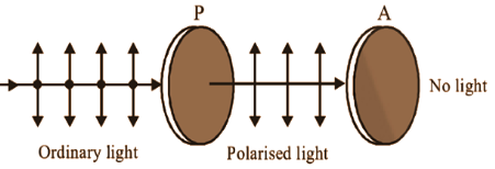
Note: If an unpolarized light is passed through a polarizer, the intensity of the transmitted polarised light will become half of the intensity of unpolarised light.
(i) Polaroids are used in making wind shields of automobiles, sun glasses etc. They helps to reduce head light glare of cares and improve colour contrast in old paintings. Polaroids are also used in 3-D motion pictures are in optical stress analysis.
9.4. Malus Law:
The intensity of a polarised light passed through an analyser will change as the square of the cosine of the angle between the plane of transmission of the analyser and the plane of the polariser. This is known as Malus law.
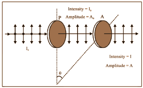
$\text{I=}{{\text{I}}_{\text{o}}}\text{co}{{\text{s}}^{\text{2}}}\text{ }\!\!\theta\!\!\text{ and }{{\text{A}}^{\text{2}}}\text{=}{{\text{A}}_{\text{o}}}^{\text{2}}\text{co}{{\text{s}}^{\text{2}}}\text{ }\!\!\theta\!\!\text{ }\Rightarrow \text{A=}{{\text{A}}_{\text{o}}}\text{cos }\!\!\theta\!\!\text{ }$
If $\text{ }\!\!\theta\!\!\text{ =}{{\text{0}}^{\text{o}}}\text{,I=}{{\text{I}}_{\text{o}}}\text{,A=}{{\text{A}}_{\text{o}}}$
If $\text{ }\!\!\theta\!\!\text{ =4}{{\text{5}}^{\text{o}}}\text{,I=}\frac{{{\text{I}}_{\text{o}}}}{2}\text{,A=}\frac{{{\text{A}}_{\text{o}}}}{\sqrt{\text{2}}}$
If $\text{ }\!\!\theta\!\!\text{ =9}{{\text{0}}^{\text{o}}}\text{,I=0,A=0}$
(ii) If ${{I}_{i}}=$ Intensity of unpolarised light.
So, ${{I}_{o}}=\frac{{{I}_{i}}}{2}$ i.e. if an unpolarised light is converted into plane polarised light ( say by passing it through a Polaroid or a Nicole-prism), its intensity becomes half and $\text{I=}\dfrac{{{\text{I}}_{\text{i}}}}{\text{2}}\text{co}{{\text{s}}^{\text{2}}}\text{ }\!\!\theta\!\!\text{ }$
Note:
Percentage of polarisation$=\dfrac{\left( {{I}_{\max }}-{{I}_{\min }} \right)}{\left( {{I}_{\max }}+{{I}_{\min }} \right)}\times 100$
10. Fresnel Distance:
The minimum distance a beam of light can travel before its deviation from straight line path becomes significant/ noticeable is known as Fresnel distance.
${{\text{Z}}_{\text{F}}}\text{ = }\dfrac{{{\text{a}}^{\text{2}}}}{\text{ }\!\!\lambda\!\!\text{ }}$
As the wavelength of light is very small, the deviation will be also very small and light can be assumed as travelling in a straight line.
So, we can neglect broadening of beam due to diffraction up to distances as large as a few metres, i.e., we can assume that light travels along straight lines and ray optics can be taken as a limiting case of wave optics.
Therefore, Ray optics can be considered as a limiting case of wave optics.
Wave Optics Class 12 Notes Physics - Basic Subjective Questions
Section–A (1 Mark Questions)
1. State the reason why two independent sources of light cannot be considered as coherent sources.
Ans. Two independent sources of light cannot be coherent. This is because light is emitted by individual atoms, when they return to ground state. Even the smallest source of light contains billions of atoms which obviously cannot emit light waves in the same phase.
2. Draw a diagram to show refraction of a plane wave front incident in a convex lens and hence draw the refracted wave front.
Ans.

3. Differentiate between a ray and a wave front.
Ans. Ray defines the path of light. Wave front is the locus of points in the light wave having the same phase of oscillation at any instant.
4. In Young's experiment the monochromatic light is used to illuminate two slits A and B as shown in figure. Interference fringes are observed on a screen placed in front of the slits. Now a thin glass plate is placed normally in the path of beam coming from the slit A, then what changes will be observed in the fringe width?

Ans.

When we placed a glass plate in the path of one of the beams, there would be a variation in the position of fringes on the screen. All the fringes appearing on the screen will be shifted. But it will not cause a change in the width of the fringe.
5. Find the angular reAnsution of a 10 cm diameter telescope at a wavelength of $5000A^{\circ}$ .
Ans. Angle reAnsution of telescope is given by;
$\Rightarrow d\theta=\dfrac{1\cdot 22\lambda }{d}$
Where,
$d\theta$ is the angular reAnsution of telescope, d is the diameter of a telescope.
$\Rightarrow d\theta \dfrac{1\cdot 22\times 5000\times 10^{-10}}{0\cdot 1}=6\cdot 1\times 10^{-6}rad$ .
Section–B (2 Marks Questions)
6. In a single slit diffraction pattern, the distance between the first minima on the left and the first minima on the right is 5 mm. The screen on which the diffraction pattern is displayed is at a distance of 80 cm from the slit. The wavelength is 6000 Å. Then find the slit width.
Ans. Slit width, $d=\dfrac{2D\lambda }{\beta _{centre}}$
Given, $D=80cm=80\times 10^{-2}m$ ,
$\lambda =6000A^{\circ}=6000\times 10^{-10}m$
and $\beta =5mm=5\times 10^{-3}m$

$\therefore d=\dfrac{80\times 10^{-2}\times 6000\times 10^{-10}\times 2}{5\times 10^{-3}}$
=0.192mm
.
7. In Young’s double slit experiment, the distance between two slits is halved and the distance between the screen and slit is made three times. Then, find the new width of the fringe.
Ans. Given that, the distance between two slits ${d}'=\dfrac{d}{2}$ and the distance between screen and slit D’ = 3D
We know that, the fringe width is
$\beta =\dfrac{D\lambda }{d}$ … (i)
According to question
$\Rightarrow \beta=\dfrac{{D}'\lambda }{{d}'}\Rightarrow {\beta }'=\dfrac{3D\cdot \lambda }{d/2}$
$\Rightarrow \beta =\dfrac{6D\lambda }{d}$ … (ii)
On dividing Eq. (ii) by Eq. (i), we get
$\dfrac{{\beta }'}{\beta }=\dfrac{\dfrac{6D\lambda }{d}}{\dfrac{D\lambda }{d}}\Rightarrow \dfrac{{\beta }'}{\beta }=6\Rightarrow {\beta }'=6\beta$
8. Two coherent sources of different intensities send waves which interfere. The ratio of maximum intensity to the minimum intensity is 25. Then find the ratio of intensities of the sources.
$\dfrac{I_{max}}{I_{min}}=\dfrac{(\sqrt{I_{1}}+\sqrt{I_{2}})^{2}}{(\sqrt{I_{1}}-\sqrt{I_{2}})^{2}}=\dfrac{25}{I}$
Ans.
$\dfrac{\sqrt{I_{1}}+\sqrt{I_{2}}}{\sqrt{I_{1}}-\sqrt{I_{2}}}=\dfrac{5}{1}\Rightarrow \dfrac{I_{1}}{I_{2}}=\dfrac{9}{4}$
9. In Young’s double slit experiment, the aperture screen distance is 2 m. The slit width is 1 mm and light of 600 nm is used. If a thin plate of glass ( $\mu$ = 1.5) of thickness 0.06 mm is placed over one of the slits, then find the lateral displacement of the fringes that will take place there.
Ans. When a thin glass plate of thickness t is placed over one of the slits, then lateral displacement is given by
Given,
$X=\dfrac{(\mu -1)tD}{d}$
Given, $\mu$ =1.5, t=0.06mm= $6\times 10^{-5}m$
and D=2m, d=1mm= $1\times 10^{-3}m$
Putting the values in the above relation, we get
$X=\dfrac{(1\cdot 5-1)\times 6\times 10^{-5}\times 2}{1\times 10^{-3}}=0\cdot 5\times 12\times 10^{-12}=6cm$
10. Two Nicols are oriented with these principal planes making an angle of 60°. Find the percentage of incident unpolarised light which passes through the system.
Ans. Intensity of polarised light from first polarizer $=\dfrac{100}{2}=5$
$I=I_{0}\;cos^{2}\;\theta =50\;cos^{2}\;60^{\circ}$
$\dfrac{50}{4}=12\cdot 5$
$\dfrac{12\cdot 5}{100}\times 100=12\cdot 5%$ .
5 Important Formulas of Physics Class 12 Chapter 10 Wave Optics
Importance of Physics Chapter 10 Wave Optics Class 12 Notes PDF
Revision notes help us quickly understand and remember key concepts before exams.
They save time by focusing on essential information and skipping unnecessary details.
They provide practical examples that show how theoretical knowledge is used in real-life situations.
Revision notes ensure thorough preparation by covering all important topics in a structured manner.
They increase confidence by clearly understanding what to expect in exams.
Accessible formats like PDFs allow for easy studying anytime and anywhere.
Tips for Learning the Physics Chapter 10 Wave Optics Class 12 Notes
Focus on the fundamentals of interference, diffraction, and polarisation. Make sure you grasp the principles behind each phenomenon.
Work through a variety of problems to apply formulas and concepts. This will help improve your understanding and improve problem-solving skills.
Familiarise yourself with the derivations of important formulas. Understanding how formulas are derived will help you remember them better.
Familiarise yourself with the wave equations for electromagnetic waves and their solutions. Practice deriving these equations and understanding their physical meaning.
Study the conditions for constructive and destructive interference in both Young's double slit experiment and interference fringes. Understand how to calculate fringe spacing and path differences.
Connect theoretical concepts to real-life applications and experiments. This makes the material more relatable and easier to remember.
Conclusion
Vedantu’s Class 12 Physics Chapter 10 Wave Optics, covers essential topics like interference, diffraction, and polarisation. By mastering these concepts and formulas, you’ll understand how light behaves in various situations. Our revision notes simplify these complex ideas, helping you to grasp and retain the material effectively. Use these notes to review key points, solve practice problems, and prepare confidently for your exams. With a solid understanding of wave optics, you’ll be well-equipped to tackle any related questions and excel in your physics studies.
Related Study Materials for Class 12 Physics Chapter 10 Wave Optics
Chapter-wise Links for Class 12 Physics Notes PDF FREE Download
Related Study Materials Links for Class 12 Physics
Along with this, students can also download additional study materials provided by Vedantu for Physics Class 12–
FAQs on CBSE Notes Class 12 Physics Chapter 10 - Wave Optics - 2026-27
1. How do the revision notes for Wave Optics Class 12 help in preparing for CBSE board exams?
Revision notes for Wave Optics Class 12 offer a structured and concise summary of core concepts such as interference, diffraction, and polarisation. These notes help students quickly recall key formulas, understand important derivations, and focus on high-yield topics essential for the board exam. By highlighting fundamental principles and including practical problem examples, revision notes enable efficient last-minute preparation.
2. What are the most important topics to focus on while revising Chapter 10 Wave Optics in Class 12 Physics?
While revising, give priority to these topics:
- Interference of light (Young's Double Slit Experiment and fringe calculations)
- Diffraction (single slit pattern, minima/maxima conditions)
- Polarisation of light (types, Malus’s Law, applications)
- Path and phase difference
- Formulas like Rayleigh criterion and Brewster’s law
A solid understanding of these ensures comprehensive exam readiness.
3. How can I quickly recall the derivation of fringe width in Young's Double Slit Experiment during revision?
The fringe width (β) is given by the formula β = (λD)/d, where λ is the wavelength of light, D is the distance between slits and the screen, and d is the slit separation. To recall the derivation, remember that constructive interference leads to bright fringes at locations where the path difference is an integer multiple of the wavelength. Use diagrams while revising to visualise the setup and steps.
4. What is the best revision strategy for mastering numericals in Wave Optics Class 12?
Mastering numericals requires regular practice of questions based on fringe width calculations, angular resolution, and optical path difference. Go through solved examples in your revision notes, understand the logic behind formula application, and attempt step-by-step solutions without skipping derivation steps. Focus on variations, such as changing slit separation or introducing a glass plate, to cover all exam patterns.
5. How do the concepts of interference and diffraction differ, and why is it important to distinguish them in revision?
Though both are wave phenomena, interference involves the superposition of two or more coherent waves from separate sources, producing a pattern of alternate bright and dark fringes. Diffraction, on the other hand, is the bending and spreading of light when it encounters an obstacle or slit, especially when the size is comparable to the wavelength of light. Distinguishing these helps in answering theoretical and application-based questions accurately.
6. Why should students understand the derivation of Malus’s Law in the context of Wave Optics revision notes?
Understanding Malus’s Law is crucial as it explains how intensity of polarised light changes when passed through an analyser. Knowing the derivation helps in answering conceptual and explanatory questions regarding polarisation, an important exam component in Wave Optics Class 12.
7. What revision tip helps in remembering the conditions for constructive and destructive interference?
Remember:
- Constructive interference: Path difference = nλ (n = 0, 1, 2,...)
- Destructive interference: Path difference = (2n-1)λ/2
8. How does a thin transparent film impact the interference pattern in Young's Double Slit Experiment?
Introducing a thin transparent film like mica or glass in the path of one beam causes a fringe shift but does not change the fringe width. The entire pattern shifts on the screen, which can be calculated using the formula for lateral shift in Wave Optics Class 12 Notes. Understanding this helps in long-answer and numerical questions.
9. In what way does polarisation help distinguish between transverse and longitudinal waves during revision?
Polarisation is a property only exhibited by transverse waves such as light, where the oscillations occur in specific directions perpendicular to propagation. Longitudinal waves, like sound in air, do not show polarisation. Including this distinction in your revision helps in answering assertion-reason and conceptual MCQs.
10. What should students focus on when reviewing diffraction patterns, especially for single slit experiments?
Focus on:
- The central maxima being the brightest and twice as wide as the subsequent fringes
- Conditions for minima: d sin θ = nλ (n = 1, 2, 3, ...)
- Resultant intensity variation from the centre to the edges
Practising related questions ensures you handle both numerical and theoretical portions effectively.
11. How is the Rayleigh criterion applied when learning about the resolving power of optical instruments in revision notes?
The Rayleigh criterion is used to determine the minimum angular separation for two point sources to be distinguished clearly using an optical device, such as a telescope or microscope. This is given by θ = 1.22λ/D, where λ is the wavelength and D is the aperture diameter. This principle links directly to concepts in diffraction and is tested regularly in board exams.
12. Why are revision notes structured with a concept map approach for Wave Optics?
Concept maps in revision notes help in visualising connections between key ideas such as interference, diffraction, and polarisation. By outlining main points and linking formulas, students can quickly identify relationships and dependencies among concepts, facilitating easier recall during exams.
13. If the slit separation is halved in the double slit experiment, what effect does this have on fringe width, and how should students approach this in revision problems?
Halving slit separation (d) in Young's experiment causes the fringe width (β) to double, as β = (λD)/d. Students should memorise this inverse relationship and practise solving variations of this scenario in revision exercises to handle application-based and HOTS questions.
14. How do CBSE revision notes for Wave Optics Class 12 differ from regular classroom notes?
CBSE revision notes focus on summarising key exam-relevant points, including important formulas, derivations, and common pitfalls. They omit unnecessary details, are arranged topic-wise for quick refresh, and often include solved sample and unsolved practice questions, making them ideal for pre-exam revision.
15. What is the significance of Fresnel distance in the context of Wave Optics and when should students use this concept during revision?
Fresnel distance indicates the minimum distance from a source beyond which the deviation of a light beam due to diffraction becomes significant. It helps explain the validity of ray optics as an approximation for wave behaviour over large distances. Knowing when to apply Fresnel distance clarifies exam questions on the boundary between wave and ray optics.