


NCERT Exemplar for Class 3 Free Download on Vedantu
Exercise MCQ - 1
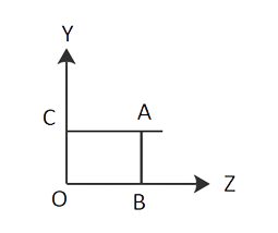
1. In a location where the magnetic field is provided by B= ${B_O}$ (2î + 3 Ĵ+ 4k̂) T, a square of side L metres sits in the x-y plane. where ${B_O}$ is constant. The flux travelling through the square has a magnitude of
(a) 2 ${B_O}{L^2}$ Wb.
(b) 3 ${B_O}{L^2}$ Wb.
(c) 4 ${B_O}{L^2}$ Wb.
(d) 29 ${B_O}{L^2}$ Wb.
Ans: Option (c)
Explanation: The total number of magnetic lines of force flowing regularly through an area put in a magnetic field is equal to the magnetic flux connected with that region, which is defined as the total number of magnetic lines of force travelling normally through an area placed in a magnetic field.
Magnetic flux = magnetic field × Area
\[\Phi {\text{ }} = {\text{ }}B \times {\text{ }}A\]
\[\; = \;\;(2 \times \hat i .\hat k + {\text{ }}3 \times \hat k.\hat j + {\text{ }}4 \times \hat k.\hat k)\]
= ${B_O}{L^2}$ [0+0+4]
= 4 ${B_O}{L^2}$ Wb
2. A loop with six corners has A(0,0,0), B(L,O,0), C(L,L,0), D(0,L,0), E(0,L,L) and F(0,L,L) (0,0,L) .A magnetic field B= ${B_O}$ (î + k̂) is present in the region. The flux flowing through the ABCDEFA loop is (in that sequence)
(a) ${B_O}{L^2}$ Wb.
(b) 2 ${B_O}{L^2}$Wb.
(c) 3${B_O}{L^2}$Wb
(d) 4 ${B_O}{L^2}$ Wb.
Ans: Option (b)
Explanation: The loop can be considered in two planes:
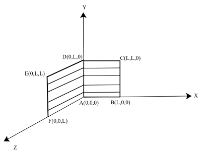
(i) ABCDA plane is in the X-Y plane. As a result, the vector A is in the Z-direction.
${A_1} = |A|\hat k = {L^2}\hat k{A_1} = |A|k = Lk$
(ii) DEFAD's plane is in the Y-Z plane.
\[{A_2} = {\text{ }}\left| A \right|\hat i {\text{ }} = {L^2}\hat i \;\]
Therefore , A is equal to \[{A_1} + {A_2}\]
\[A{\text{ }} = \;\;{L^2}(\hat i + \hat k)\]
\[B = {\text{ }}{B_O}(\hat i + \hat k)\]
Magnetic flux = magnetic field × Area
\[\Phi {\text{ }} = {\text{ }}B \times {\text{ }}A\]
\[\Phi {\text{ }} = {B_o}(\hat i + \hat k).{L^2}(\hat i + \hat k)\]
\[ = \;{\text{ }}{B_O}.{L^2}[\hat i .\hat i {\text{ }} + \hat i .\hat k + \hat k.\hat i + \hat k\hat k]\]
\[ = \;{\text{ }}{B_O}.{L^2}\] [1+0 +0+ 1]
\[ = \;{\text{ 2}}{B_O}.{L^2}\]Wb
3. The axis of a cylindrical bar magnet is rotated. From the axis, a wire is linked and brought into contact with the cylinder surface through a contact. Then
(a) In the ammeter A, a direct current flows.
(b) the ammeter has no current flowing through it.
(c) an alternating sinusoidal current with a period of 2 /ω passes through the ammeter A.
(d) Through the ammeter A, a time-varying non-sinusoidal current flows.
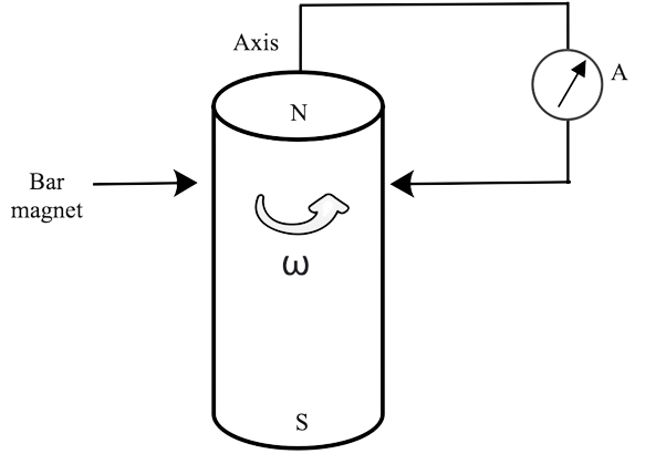
Ans: Option (b)
Explanation: This issue makes advantage of the electromagnetic induction phenomena. Induced emf occurs when the number of magnetic lines of force (magnetic flux) travelling through a circuit change (or when a moving conductor cuts the magnetic flux). Only as long as there is a shift or cutting of flow does the induced emf remain. When a cylindrical bar magnet is spun about its axis, there is no change in the circuit's flux, hence no emf is generated and no current flows through the ammeter A. As a result, there is no deflection on the ammeter.
4. As illustrated in the diagram, there are two coils A and B. When A is pushed towards B, a current begins to flow in B and ends when A is stopped. In A, the current is going in the other direction. When A moves, B remains immobile.
We may deduce that
(a) in A, there is a continuous stream flowing clockwise.
(b) In A, there is a changing current.
(c) In A, there is no current.
(d) In A, there is a steady stream flowing counterclockwise.
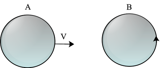
Ans: Option (d)
Explanation: An emf will be produced in coil B due to variations in the flux associated to coil B. When coil A stops moving, current in coil B becomes zero; this is only feasible if coil A's current is constant. If the current in coil A varies, there must be some flux variation and so an induced emf. As a result, even if coil A is not moving, an induced current will flow through coil B.
5. Problem 4 is repeated with the exception that coil A is configured to spin along a vertical axis (figure). If A is at rest, no current flows in B. When the current in coil B (at t = 0) is counter-clockwise and the coil A is as indicated at this moment, t = 0, the current in coil A is
(a) constant current clockwise.
(b) changing current in a clockwise direction.
(c) changing current in a counter clockwise direction.
(d) counter clockwise steady current
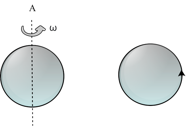
Ans: Option (a)
Explanation: Because Lenz's law applies to our situation, we'll start with Lenz's law. The direction of induced emf/induced current is determined by Lenz's law. The direction of induced emf or current in a circuit is such that it opposes the source that creates it, according to this rule. This law is based on the law of energy conservation. When the current in coil B is counter-clockwise (at t= 0), and coil A is regarded above it. The current flow in coil B is counter clockwise, equating to the north pole of the magnet, and magnetic field lines are eliminated upward to coil A. By Lenz's rule, when coil A starts spinning at t = 0, the current in A remains constant in the clockwise direction.
6. With a constant number of turns N, the self-inductance L of a solenoid of length l and cross-section area A grows as
(a) l and A increase
(b) l declines and A increases
(c) l increases and A decreases
(d) both l and A decrease.
Ans: Option (b)
Explanation: A solenoid's self-inductance L is determined by a number of factors, including the shape and magnetic permeability of the core material.
$B = {B_O}\sin (\omega t)\hat k$
n = N/l (number of turns per length unit)
1. Number of turns: The more turns a solenoid has, the higher its self inductance.
2. Cross-sectional area: The greater the cross-sectional area of the solenoid, the higher its self-inductance.
3. The core material permeability. If a solenoid is coiled over an iron core with a relative permeability of r, its self-inductance increases by r time μr
When a long solenoid with A turns and a material of relative permeability (e.g., soft iron with a high value of relative permeability) is filled inside with a material of relative permeability (e.g., soft iron with a high value of relative permeability), its self-inductance is $L{\text{ }} = {\text{ }}\dfrac{{{\mu _r}{\mu _o}{n_2}A}}{l}\;$
Because L is directly proportional to area and inversely proportional to length, the self-inductance L of a solenoid grows as l lowers and A increases. The geometry of the devices, as well as the medium's permittivity/permeability, affect the self and mutual inductance of capacitance and resistance.
MCQ - 2
7. The temperature of a metal plate is rising. It might be because
(a) the plate is conducting a direct current
(b) it is in a time-varying magnetic field
(c) it is in a space-varying magnetic field that does not vary with time.
(d) the plate has a current flowing through it (direct or alternating).
Ans: Options (a),(b) and (c)
Explanation: When a changing magnetic flux is applied to a bulk piece of conducting material, eddy currents, or circulating currents, are produced in the material. Eddy currents have huge magnitudes and heat up the conductor since the bulk conductor's resistance is generally low.
(1) These are circulating currents, similar to water eddies.
(2) Foucault provided the experimental notion, thus the term "Foucault current."
(3) In a metallic block, the generation of eddy currents results in the loss of electric energy in the form of heat.
(4) The resistance route for eddy current circulation is increased by lamination and slotting procedures, weakening them and minimising losses caused by them.
8. A coil that is not linked to an external voltage source produces an emf. This might be because
(a) the coil is in a time-varying magnetic field
(b) the coil is moving in a time-varying magnetic field
(c) the coil is moving in a constant magnetic field
(d) the coil is stationary in an external spatially changing magnetic field that does not change with time.
Ans: Options (a), (b) and (c)
Explanation: As we all know, when the quantity of magnetic lines of force (magnetic flux) travelling through a circuit varies, an induced emf is created in the circuit. Only as long as there is a shift or cutting of flow does the induced emf remain. When the isolated coil is put in the region of a time varying magnetic field, whether the coil is travelling in a constant magnetic field or in a time varying magnetic field, the magnetic flux associated with the coil varies.
9. The mutual inductance ${{\bf{M}}_{{\bf{21}}}}$ of coil 1 with respect to coil 2
(a) rises as they get closer
(b) is dependent on the current running through the coils
(c) increases as one of them is rotated about an axis
(d) is like ${{\bf{M}}_{{\bf{21}}}}$ of coil 2 with respect to coil 1.
Ans: Options (a) and (d)
Explanation: Mutual induction is described as a characteristic of coils that allows them to resist current changes in another coil. When the current of one coil changes, the flow changes as well, causing EMF in the other coil. Mutual induction is the term for this occurrence. An inductor is a circuit component that represents inductance, and Oliver Heaviside coined the word inductance in 1886.
10. In the presence of a magnetic field, a circular coil extends radially but produces no electromotive force. This could be because
(a) the magnetic field is constant
(b) the magnetic field is in the same plane as the circular coil and may or may not vary
(c) the magnetic field has a perpendicular (to the plane of the coil) component whose magnitude is decreasing suitably
(d) there is a constant magnetic field in the perpendicular (to the plane of the coil) direction.
Ans: (b) The magnetic field is in the same plane as the circular coil and may or may not vary
(c) The magnetic field has a perpendicular (to the plane of the coil) component whose magnitude is decreasing suitably.
Explanation: When the number of magnetic lines of force (magnetic flux) travelling through a circuit varies, an induced emf is generated in the circuit. Only as long as there is a shift or cutting of flow does the induced emf remain.
The induced emf is calculated from the rate of change of magnetic flux in the circuit.
i.e.,
The coil produces no electromotive force, according to the issue. The different arrangements must then be conceived in such a way that the magnetic flux associated with the coil remains constant even when the coil is put and extended in a magnetic field.
When a circular coil expands radially in a region of magnetic field, the magnetic field is in the same plane as the circular coil, or we can say that the magnetic field's direction is perpendicular to the area's direction (increasing), their dot product is always zero, and thus the change in magnetic flux is also zero.
Very Short Answer Type s (VSA)
11. Consider a magnet enclosed by a wire and controlled by an on/off switch S. (figure). Will a current flow in the circuit if the switch is thrown from the off position (open circuit) to the on position (closed circuit)? Explain
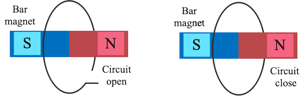
Ans: There will be no current induced since there is no change in the magnet or the circuit area. In addition, the angle remains unchanged. When the number of magnetic lines of force (magnetic flux) travelling through a circuit varies, an induced emf is generated in the circuit. Only as long as there is a shift or cutting of flow does the induced emf remain. The induced emf is calculated from the rate of change of magnetic flux in the circuit.
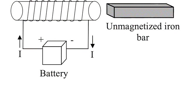
12. A current is carried via a wire in the shape of a tightly wound solenoid that is linked to a DC source. Will the current rise or decrease if the coil is extended so that gaps appear between consecutive sections of the spiral coil? Explain.
Ans: The magnet flux will leak through the spaces between two turns as the coil is stretched. The e.m.f is formed in a neighbouring coil, which opposes the rise or reduction in flux in the coil, according to Lenz's law. As a result, as the coil is stretched, the current increases. The number of turns per unit length (n) decreases as the coil is stretched. As a result, L or reactance drops, causing current to rise.
13. A solenoid is linked to a battery and receives a constant current. Will the current rise or decrease if an iron core is introduced into the solenoid? Explain.
Ans: This problem is based on Lenz's rule, which states that induced emf or current in a circuit should be directed in the opposite direction of the cause that creates it. The magnetic field increases when the iron core is introduced in the current carrying solenoid owing to the magnetisation of the iron core, and therefore the flux increases. As a result, the induced emf in the coil must fight this rise in flux, and the current in the coil must be induced in such a way that it opposes the growing magnetic field, which may be accomplished by reducing current. As a result, the current will drop.
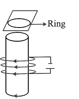
14. Consider a metal ring that is frequently kept on top of a fixed solenoid (for example, on a piece of cardboard) (figure). The axis of the solenoid is parallel to the centre of the ring. The metal ring bounces up when the current is suddenly turned on. Explain.

Ans : This problem is based on Lenz's rule, which states that induced emf or current in a circuit should be directed in the opposite direction of the cause that creates it.
There is no flux associated with the ring at first, or we may say that flux through the ring is 0 at first. When the switch is closed, current flows through the circuit, and magnetic flux passes through the ring. As a result, the flow increases. This rise will be resisted, according to Lenz's law, and this can happen if the ring travels away from the solenoid. This occurs because the flux increases produce an anticlockwise current (as viewed from the top of the ring in figure. ), i.e The current in the solenoid will flow in the other direction.
15. Consider a metal ring on top of a fixed solenoid carrying a current I, which is supported by a cardboard. The axis of the solenoid is parallel to the centre of the ring. What will happen to the ring if the solenoid's current is turned off?\
Ans: When the switch is flipped on, current in the solenoid circuit stops flowing. When the current in the circuit is turned off, the magnetic flux associated with the solenoid falls to zero, or we might say the magnetic flux associated with the ring diminishes. This decrease in flux will be resisted by Lenz's law, and the ring will suffer downward push towards the solenoid. This occurs because when the current I decreases, the decreasing flux is increased by a clockwise current (as seen from the top of the ring in figure). This is possible if the induced magnetic field's direction is the same as the solenoids. When viewed from the bottom of the ring, this creates the opposite feeling of current flow in the ring, with the solenoid creating opposing magnetic poles in front of each other. As a result, they'll -attract each other, but because the ring is on the cardboard, it won't be able to go lower.
16. Let us take a metallic pipe with an inner radius of 1 cm. When a cylindrical bar magnet with a radius of 0.8cm is put through a metallic pipe, it takes longer to come down than when an identical unmagnetized cylindrical iron bar is dropped through the pipe. Explain.
Ans: The direction of induced emf/induced current is determined by this law. The direction of induced emf or current in a circuit is such that it opposes the source that creates it, according to this rule. This law is based on the law of energy conservation.
Eddy Current is a term used to describe a current that is When a changing magnetic flux is given to a large piece of conducting material, it induces circling currents known as eddy currents. Eddy currents have huge magnitudes and heat up the conductor since the bulk conductor's resistance is generally low.
When a cylindrical bar magnet is dropped into a metallic pipe, the flux associated with the cylinder varies, resulting in eddy currents in the pipe. According to Lenz's law, these currents will resist the magnet's motion, resulting in induction.
17. ${\bf{B}} = {\text{ }}{{\bf{B}}_{\bf{o}}}{\bf{cos}}{\text{ }}{\bf{\omega t}}$ k determines the magnetic field in a specific area and in the magnetic field, a coil of radius a with resistance R is positioned in the x-y plane with its centre at the (a, 0, 0). Determine the current's size and direction at ${\bf{t}}{\text{ }} = \dfrac{{{\bf{\pi }}{\text{ }}}}{{2{\bf{\omega }}}},{\text{ }}{\bf{t}}{\text{ }} = \dfrac{{{\bf{\pi }}{\text{ }}}}{{{\bf{\omega }}{\text{ }}}}{\bf{and}}{\text{ }}{\bf{t}}{\text{ }} = \dfrac{{{\bf{3\pi }}}}{{{\bf{\omega }}{\text{ }}}}$
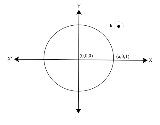
Ans: The direction of the magnetic field is along the z-axis.
Φ = B.A = BA cos θ
Using electromagnetic induction as defined by Faraday's law
$I = \dfrac{{{B_O}(\pi {a^2}){\bf{\omega }}\sin {\bf{\omega }}t}}{R}$
As a result, current at ${\bf{t}}{\text{ }} = \dfrac{{{\bf{\pi }}{\text{ }}}}{{2{\bf{\omega }}}}$ is $I = \dfrac{{{B_O}(\pi {a^2}){\bf{\omega }}}}{R}$ along Ĵ because when we substitute the value of t in $\sin {\bf{\omega }}t$ we get $\sin ({\bf{\omega }} \times \dfrac{\pi }{{2{\bf{\omega }}}}) = \sin \dfrac{\pi }{2} = 1$ current at ${\bf{t}}{\text{ }} = \dfrac{{{\bf{\pi }}{\text{ }}}}{{\bf{\omega }}}$ is $I = \dfrac{{{B_O}(\pi {a^2}){\bf{\omega }} \times 0}}{R}$ because when we substitute the value of t in $\sin {\bf{\omega }}t$ we get $\sin ({\bf{\omega }} \times \dfrac{\pi }{{\bf{\omega }}}) = \sin \pi = 0$ current at ${\bf{t}}{\text{ }} = \dfrac{{3{\bf{\pi }}{\text{ }}}}{{\bf{\omega }}}$ is $I = \dfrac{{{B_O}(\pi {a^2}){\bf{\omega }}}}{R}$ along - Ĵ because when we substitute the value of t in $\sin {\bf{\omega }}t$ we get $\sin ({\bf{\omega }} \times \dfrac{{3\pi }}{{2{\bf{\omega }}}}) = \sin \dfrac{{3\pi }}{2} = 0$
18. Consider the case of a closed loop. C in the presence of a magnetic field. Using the formula $\phi = {B_1}{\text{.d}}{{\text{A}}_1} + {B_2}{\text{.d}}{{\text{A}}_2} + ......$ the flux travelling through the loop is specified by selecting a surface whose edge corresponds with the loop. Would we obtain the same result for flux if we choose two other surfaces S1 and S2 with C as their edge? Justify your response.
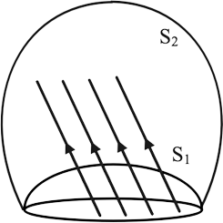
Ans: For magnetic flux, we'd obtain the same response. Let's take a closer look at the cause behind this. The number of magnetic field lines travelling through the surface might be regarded as the magnetic flux associated with the surface. Assume that $\;d\phi {\text{ }} = {\text{ }}B.dA$ Magnetic lines in the area A to B are represented by dA. Magnetic field lines have no beginning or end in space, and this attribute is founded on the idea of continuity. As a result, the number of lines that pass-through surface S1 must equal the number of lines that pass-through surface S2. As a result, we receive the same magnetic flux in both circumstances.
19. Calculate the current in the wire. The resistance of wire PQ is minimal. B, the paper's magnetic field is escaping. PQ travels smoothly over two conducting parallel wires separated by a distance d, resulting in a constant angle. For the setup indicated in the diagram
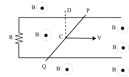
Ans: Because of the motion along Cd, the motional electric field E is
$\;E = v \times B$.
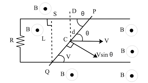
E will have a direction that is perpendicular to both v and B.
As we know $F = q{\text{ }} \times {\text{ }}B$
F is the force acting on PQ's free charge particle.
So, the motional e.m.f $\varepsilon = {\text{ }}E{\text{ }}along{\text{ }}PQ \times {\text{ }}effective{\text{ }}length{\text{ }}PQ$
Electric field will be along$\;PQ = v \times B = v{\text{ }}sin\;\theta $ $B = v{\text{ B}}sin\;\theta $
$\varepsilon = (vB\sin \theta )\left( {\dfrac{d}{{\sin \theta }}} \right)$
$\varepsilon \; = {\text{ }}v{\text{ }} \times B \times {\text{ }}d$
Therefore, the Induced current will be
$\dfrac{\varepsilon }{R} = \dfrac{{vBd}}{R}$
So, we can see that it can be independent of q
20. Figure shows a graph of current travelling through a solenoid (current vs time). When does the back electromotive force (u) reach its maximum? Find the back emf at t = 3s, 15s, and 40s if the back emf at t = 3s is e. Straight line segments are OA, AB, and BC.
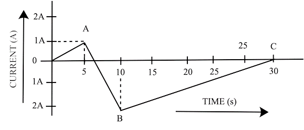
Ans: We may deduce from the graph that when the rate of change of magnetic flux reaches its highest, the electromagnetic force, which is proportional to the rate of change of current, reaches its maximum. When the time axis reaches its maximum angle at AB, the present rate will be at its highest.
As a result, when t = 3 seconds, s = OA slope
As a result, the present rate of change at $\;t{\text{ }} = {\text{ }}3{\text{ }} = \dfrac{1}{4}{\text{ }}A/s$
As a result, the electromotive force is equal to L/5.
It is -3e when the emf is between 5 to 10 seconds. It is$\dfrac{{ + 1}}{{2e}}$ when the emf is between 10 to 30 seconds and when the emf is at 40 seconds, $\dfrac{{dl}}{{dt}}$= 0
21. There are two coils A and B separated by some distance. If a current of 2 A flows through A, a magnetic flux of ${10^{ - 2}}$ Wb passes through B (no current through B). If no current passes through A and a current of 1 A passes through B, what is the flux through A?
Ans: Let's say ${{\bf{I}}_A}$current is flowing through coil A, which has mutual inductance ${M_{{\bf{A}}B}}$ with coil B.
${N_A}$denotes the number of turns in coil A.
${N_B}$denotes the number of turns in coil B.
${\phi _A}$ is the flux associated with coil A as a result of coil B
${\phi _B}$ is the flux associated with coil B as a result of coil A
Then, ${M_{{\bf{A}}B}}$=Mutual inductance of coil B in relation to coil A
So, the total flux that passes through B is
$B = {M_2}{\phi _2} = {M_{BA}}{I_1}$ and ${10^{ - 2}} = {M_{BA}} \times 2$
${M_{BA}} = \dfrac{{{{10}^{ - 2}}}}{2} = 5mH$
So, the total flux that passes through B is
$B = {M_A}{\phi _A} = {M_{AB}}{I_2}\;$
As we know ${M_{AB}} = {M_{BA}}$
Hence, we have flux through A $ = 5{\text{ }}mH{\text{ }} \times {\text{ }}1{\text{ }}Wb = {\text{ }}5mW$
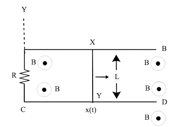
22.A magnetic field $B = {B_O}\sin (\omega {\text{ }}t)\hat k$ spans a vast area when a wire AB moves smoothly over two parallel conductors separated by d.The wires are arranged in an x-y plane. The resistance of the wire AB (of length d) is R, whereas the resistance of the parallel wires is insignificant. What is the current in the circuit if AB moves at velocity v? What force is required to maintain the wire travelling at a constant speed?
Ans: Long parallel conducting wires CA and OB are linked by d and conductor CO in the diagram. ACOB has a minimal resistance. At t=0, wire AB should be at x=0, i.e. on the Y-axis. AB is now moving with velocity v$\hat i$. Let the location of conductor AB be x(t) =v$\hat i$t at any time t. Motional e.m.f. across AB
${V_{AB}} = \dfrac{{{W_{AB}}}}{q} = \dfrac{{F.d}}{q} = \dfrac{{qv\hat i \times B}}{q}.d$
${V_{AB}} = v\hat i \times {B_0}\;sin{\text{ }}\omega t.\hat k \times {\text{ }}d$
${\varepsilon _1} = {B_O}\sin \omega tv(\hat i \times \hat k)d = {B_O}dv\sin \omega t( - \hat j)$
${\varepsilon _1} = - {B_O}\sin \omega t( - \hat j)$ (along –ve Y direction in AB)
when AB is at t=1, e.m.f. due to change in magnetic field from t=0 to t=1 (x,0)
${\varepsilon _2} = \dfrac{{ - d\phi }}{{dt}} = \dfrac{{ - d}}{{dt}}\vec B.\vec A = \dfrac{{ - d}}{{dt}}[{B_O}\sin \omega t\hat k.(x.d)\hat k]$
Area vector A is along $\hat k$
${\varepsilon _2} = \dfrac{{ - d}}{{dt}}({B_o}\sin \omega txd)$
${\varepsilon _2} = - {B_o}xd\omega \cos \omega txd$
${\varepsilon _2} = - {B_o}xd\omega \cos \omega t$
Total magnitude of e.m.f =$ - {B_o}vd\sin \omega t - {B_o}xd\sin \omega t$
$\varepsilon = - {B_o}d[v\sin \omega t + x\omega \cos \omega t]$
According to the Fleming Right Hand Rule, electric induced current flows clockwise in a loop from (A to B).
$I = \dfrac{\varepsilon }{R} = \dfrac{{{B_O}d}}{R}[v\sin \omega t + \omega x\cos \omega t]$
F is the force acting on the conductor. $AB = BIdsin\theta $
$\theta $ is angle between B($ - \hat i$) and I($ - \hat j$)=90°
$F = I \times Bdl$
$ = I( - \hat j) \times B(\hat k)d\sin \theta $
$ = IB(\hat j \times \hat k)d\sin {90^0} = - IB(\hat i)d$
$F = - \hat iIBd$
It demonstrates that the force on AB is directed toward –x, which may be verified using Fleming's left-hand rule.
$\;\left| F \right| = I{\text{ }}Bd$
It will be in the positive x direction +I opposite to maintain the wire moving at a steady speed. to the force of electromagnetic
$F = B.dI = |B|.d\dfrac{\varepsilon }{R}$
$F = \dfrac{{B.d{B_O}d}}{R}[v\sin \omega t + \omega x\cos \omega t]$
$ = \dfrac{{{B_o}\sin \omega t{B_O}{d^2}}}{R}[v\sin \omega t + \omega x\cos \omega t]$
$F = \dfrac{{{B_o}^2{d^2}\sin \omega t}}{R}[v\sin \omega t + \omega x\cos \omega t]$
23.As illustrated in Figure, a conducting wire XY with mass m and negligible resistance moves easily between two parallel conducting wires. Due to the AC, the closed circuit has a resistance R. The conductors AB and CD are ideal.$\;B\; = Bt\left( {\hat k} \right)$ .There is a magnetic field.
(i) Write down the equation for the wire XY's acceleration.
Ans: At t=0, let wire XY be at x=0.
And x=x is at t=t (t)
The magnetic flux is a time-dependent quantity.
$\phi \left( t \right) = B\left( t \right) \times A$
$\phi \left( t \right) = B\left( t \right)\left[ {l.x\left( t \right)} \right]$
$\varepsilon = - \dfrac{{d\phi (t)}}{{dt}} = - \dfrac{{dB(t)}}{{dt}}l.x(t) - B(t)l.\dfrac{{dx(t)}}{{dt}}$
$\varepsilon = - \dfrac{{dB(t)}}{{dt}}l.x(t) - B(t)lv(t)$
In loop XYAX, the direction of induced current determined by Fleming's Right Hand Rule or Lenz's rule is clockwise.
$\varepsilon = \dfrac{\varepsilon }{R} = \dfrac{{ - l}}{R}\left[ {x(t)\dfrac{{db(t)}}{{dt}} + B(t)v(t)} \right].............(1)$
The conductor is being acted upon by a force.
$\;F = B\left( t \right){\text{ }}I{\text{ }}l{\text{ }}sin{\text{ }}90^\circ $
$\;F = B\left( t \right){\text{ }}I{\text{ }}l{\text{ }}$
$\;F = \dfrac{{B\left( t \right){\text{ }}I{\text{ }}l{\text{ }}}}{R} = \dfrac{{ - B(t){l^2}}}{R}\left[ { - \dfrac{{dB}}{{dt}}.x(t) - B(t).v(t)} \right]$
$\dfrac{{\;m{d^2}x}}{{d{t^2}}} = \dfrac{{ - B(t){l^2}}}{R}\left[ { - \dfrac{{dB}}{{dt}}.x(t) - B(t).v(t)} \right]............(2)$
(ii) Assuming$v{\text{ }}\left( 0 \right){\text{ }} = {\text{ }}{u_o}$, find v(t) if B is time independent.
Ans: B is now time independent, i.e., it does not vary with time or remains constant.
$\dfrac{{dB}}{{dt}} = 0$, B(t)=B and v(t)=v ……...(3)
Putting (3) in (2) we get
$\dfrac{{\;{d^2}x}}{{d{t^2}}} = \dfrac{{ - {l^2}}}{{mR}}\left[ {0 + B.v} \right]$
$\dfrac{{\;{d^2}x}}{{d{t^2}}} + \dfrac{{{B^2}{l^2}}}{{mR}}\dfrac{{\;dx}}{{dt}} = 0$
$\dfrac{{\;dv}}{{dt}} + \dfrac{{{B^2}{l^2}}}{{mR}}v = 0$
We can integrate using a variable separable from a differential equation.
$v = A\exp \left( {\dfrac{{ - {l^2}{B^2}t}}{{mR}}} \right)$ at t=0, v=u
$v(t) = u\exp \left( {\dfrac{{ - {l^2}{B^2}t}}{{mR}}} \right)............(4)$
(iii) For (b), prove that the kinetic energy of XY decreases by the same amount as the heat lost in R.
Ans: Power consumption is represented as $P = {I^2}R$
As a result, the energy spent during the time interval dt is expressed as $ = {\text{ }}\dfrac{m}{{2{\text{ }}{u_o}^2}}\;--{\text{ }}\dfrac{m}{{2{\text{ }}{v^2}\left( t \right)}}$
The kinetic energy is decreasing, as shown by the equation above.
Therefore, energy consumed in time interval dt is given as \[\dfrac{m}{2}u_{0}^{2}-\dfrac{m}{2}{{v}^{2}}\left( t \right)\]
The above equation shows that there is a decrease in the kinetic energy.
24. ODBAC is a stationary rectangular conductor with low resistance (CO is disconnected), whereas OP is a conductor that spins clockwise with an angular velocity ω. The whole system is surrounded by a homogeneous magnetic field B that runs parallel to the surface of the rectangular conductor ABDC. ABDC is in electric contact with the conductor OP. The resistance of the revolving conductor is λ per unit length. Determine the current in the revolving conductor, which spins 180 degrees.
Ans: (i) Allowing the rotating of the conductor to come into touch with BD at Q, forming an angle. $0^\circ < \theta < 45^\circ $

In ΔODQ magnetic flux is $\phi $
$\phi = B.A$
The angles of B and A are either 0 degrees or 180 degrees.
$Q = B \times \dfrac{1}{2}l \times QD$
$\phi = B.A\cos 0 = BA = B\dfrac{1}{2} \times l.l\tan \theta $
$\phi = \dfrac{1}{2}B{l^2}\tan \theta $, here $\theta = \omega t$
By using Faraday's law of EMI, the magnitude of the induced emf may be calculated.
$|\varepsilon | = \left| {\dfrac{{d\phi }}{{dt}}} \right| = \dfrac{1}{2}B{l^2}\omega {\sec ^2}\omega t$
Where R is the resistance of the rod in contact, the current produced in the circuit will be $I = \dfrac{\varepsilon }{R}$
$R = \lambda x = \dfrac{{\lambda l}}{{\cos \omega t}}$
$I = \dfrac{1}{2}\dfrac{{B{l^2}\omega }}{{\lambda l}}{\sec ^2}\omega t\cos \omega t = \dfrac{{Bl\omega }}{{2\lambda \cos \omega t}}$
(ii) Now, allow the OP rod to make contact with the AB side. And after some time interval t, the length of the contact's OQ, which is$\dfrac{\pi }{{4\omega }} < t < \dfrac{{3\pi }}{{4\omega }}or\dfrac{T}{8} < t < \dfrac{{3T}}{8}$ let it be x. The flux in the OQBD region is high.
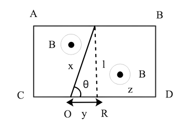
$\phi = \left( {{l^2} + \dfrac{1}{2}\dfrac{{{l^2}}}{{\tan \theta }}} \right)B$, here $\theta = \omega t$
As a result, the amplitude of induced emf in the loop is $|\varepsilon | = \left| {\dfrac{{d\phi }}{{dt}}} \right| = \dfrac{{B{l^2}\omega {{\sec }^2}\omega t}}{{2{{\tan }^2}\omega t}}$The induced current in the circuit is $I = \dfrac{{Bl\omega }}{{2\lambda \cos \omega t}}$
(iii) Now, allow the OP rod to make contact with the AB side. And after some time interval t, the length of the contact's OQ, which is$\dfrac{{3\pi }}{{4\omega }} < t < \dfrac{\pi }{\omega }or\dfrac{{3T}}{8} < t < \dfrac{T}{2}$ let it be x. The flux in the OQBD region is high

$\phi = \left( {2{l^2} + \dfrac{1}{2}\dfrac{{{l^2}}}{{\tan \theta }}} \right)B$
As a result, the amplitude of induced emf in the loop is $|\varepsilon | = \left| {\dfrac{{d\phi }}{{dt}}} \right| = \dfrac{{B{l^2}\omega {{\sec }^2}\omega t}}{{2{{\tan }^2}\omega t}}$
The induced current in the circuit is $I = \dfrac{{Bl\omega }}{{2\lambda \sin \omega t}}$
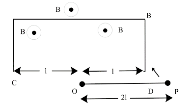
25. Considering an infinitely long wire carrying a current I (t) with $\dfrac{{dI}}{{dt}} = \lambda = {\text{constant}}$ If the resistance of wire ABCD is R, calculate the current generated in the rectangular loop.
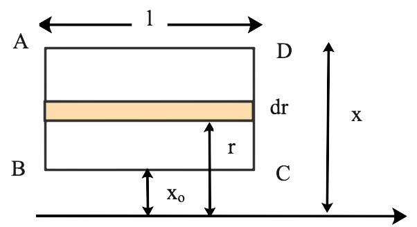
Ans: Consider a strip with a width of dr and a length of l inside a rectangle at a distance of r from the current carrying conductor surface. The magnetic field is perpendicular to the paper above and runs the length of the strip.
$l = B(r) = \dfrac{{{\mu _o}I}}{{2\pi r}}l.B(r)$
The flux in the strip $\phi = \dfrac{{{\mu _o}I}}{{2\pi }}l\int\limits_{{x_o}}^x {\dfrac{{dr}}{r}} $
$\phi = \dfrac{{{\mu _o}Il}}{{2\pi }}{\log _e}\dfrac{x}{{{x_o}}}$
$\varepsilon = \dfrac{{ - d\phi }}{{dt}}$
$IR = \dfrac{{ - d\phi }}{{dt}}$
$I = \dfrac{1}{R}\dfrac{d}{{dt}}\left[ {\dfrac{{{\mu _o}Il}}{{2\pi }}{{\log }_e}\dfrac{x}{{{x_o}}}} \right] = \dfrac{{{\mu _o}Il}}{{2\pi R}}{\log _e}\dfrac{x}{{{x_o}}}\dfrac{{dI}}{{dt}}$
$I = \dfrac{{{\mu _o}\lambda l}}{{2\pi R}}{\log _e}\dfrac{x}{{{x_o}}}(because\dfrac{{dI}}{{dt}} = \lambda )$
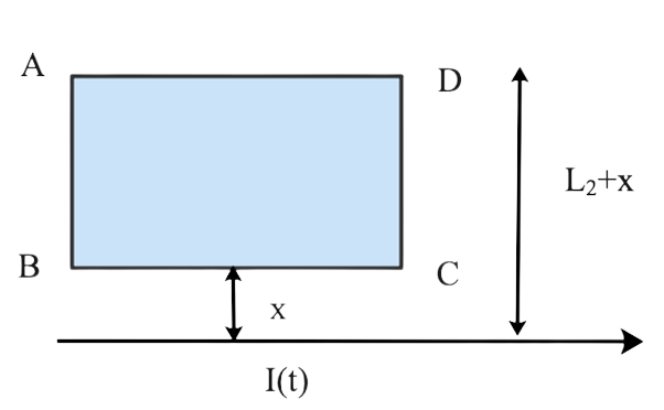
26. For 0 t T and I (0) = 0 for t > T, a rectangular loop of wire ABCD is kept near to an infinitely long wire carrying a current $I(t) = {I_O}\left( {1 - \dfrac{t}{T}} \right)$. In time T, calculate the total charge travelling through a particular point in the loop. The loop has a resistance of R.
Ans: If t is the instantaneous current then,
$I\left( t \right){\text{ }} = {\text{ }}\dfrac{1}{R}{\text{ }}\dfrac{{d\phi }}{{dt}}$
If q is the charge passing in time t
$I\left( t \right){\text{ }} = {\text{ }}\dfrac{{dQ}}{{dt}}$
${\text{ }}\dfrac{{dQ}}{{dt}}{\text{ = }}\dfrac{1}{R}{\text{ }}\dfrac{{d\phi }}{{dt}}$
Integrating the equation we get,
$\int\limits_{{Q_1}}^{{Q_2}} {dQ = \dfrac{1}{R}\int\limits_{\phi {}_1}^{{\phi _2}} {d\phi } } $
${Q_2}(t) - {Q_1}(t) = \dfrac{1}{R}{\phi _2}(t) - {\phi _1}(t)$
Magnetic flux owing to current carrying wire at a distance x' for magnetic flux in rectangle
$Q(t) = \dfrac{{{\mu _o}I(t)}}{{2\pi x'}}$
If length of strip is L1 so total flux on strip of length at distance x’ is
$Q(t) = \dfrac{{{\mu _o}I(t)}}{{2\pi x'}}{L_1}$
$Q(t) = \dfrac{{{\mu _o}{L_1}}}{{R2\pi }}{\log _e}\left( {\dfrac{{{L_2} + x}}{x}} \right)(I - 0)$
$Q(t) = \dfrac{{{\mu _o}{L_1}{I_1}}}{{R2\pi }}\log \left( {\dfrac{{{L_2} + x}}{x}} \right)$
27. A magnetic field B is restricted to a circular area r a and points out of the paper (the z-axis), with r = 0 at the centre. In the x–y plane, a charged ring (charge = Q) with radius b, b > a, and mass m has its centre at the origin. The ring is at rest and free to spin. In time $\Delta $ t, the magnetic field is brought to zero.After the field has vanished, calculate the angular velocity $\omega $ of the ring.
Ans: The magnetic flux related to the ring decreases from maximum to zero when the magnetic field is decreased to zero in time. The e.m.f. is caused by a change in magnetic flux across the conducting ring. The electric field across the ring is caused by the induced e.m.f.
The induced e.m.f. in metallic ring=(E×2πb) (V=Ed) …….(1)

Faraday's law of electromotive force (e.m.f.)
The induced e.m.f. is the rate at which magnetic flux changes $ = \dfrac{{B\pi {a^2}}}{{\Delta t}}...........(2)$
From (1) and (2) we get
$2\pi bE = \dfrac{{B\pi {a^2}}}{{\Delta t}}$
Because the charged ring is subjected to an electric force=QE
This electric force tries to spin the ring that has been provided by
=Force × Perpendicular distance
$ = QE \times 2b = Qb\dfrac{{B\pi {a^2}}}{{2\pi b\Delta t}}$
Torque on ring$ = Q\dfrac{{B{a^2}}}{{2\Delta t}}$
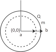
Angular momentum shifts $ = Q\dfrac{{B{a^2}}}{2}$
Because the ring's initial momentum was zero.
As a result, the ring's ultimate momentum$ = Q\dfrac{{B{a^2}}}{2}$
$\omega = \dfrac{{QB{a^2}}}{{2m{b^2}}}$
28. A rod with mass m and resistance R travels smoothly across two parallel perfectly conducting wires that are maintained slanted at an angle theta to the horizontal. The circuit is completed at the top by a perfect conductor. Along the vertical axis, there is a constant magnetic field B. Find the rod's velocity as a function of time if it is originally at rest.
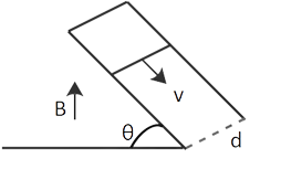
Ans: Induced current flows as a result of this.
$i = \dfrac{{v(B\cos \theta )d}}{R}$
where R is the rod's resistance. The current-carrying rod is now subjected to a magnetic force generated by${F_m} = iBd$
(in a backwards horizontal direction)
The magnetic force component is now parallel to the inclined plane in the upward direction.${F_{||}} = {F_m}\cos \theta = iBd\cos \theta = \dfrac{{v(B\cos \theta )d}}{R}Bd\cos \theta $
Where, V=dx/dt
In addition, the component of weight (mg) that is parallel to the inclined plane and moves downward $ = mg\sin \theta $
Newton's second law of motion now applies.
$m\dfrac{{{d^2}x}}{{dt{}^2}} = mg\sin \theta - \dfrac{{B\cos \theta d}}{R}\dfrac{{dx}}{{dt}}.BD\cos \theta $
$\dfrac{{dv}}{{dt}} + \dfrac{{{B^2}{d^2}}}{{mR}}{(\cos \theta )^2}v = g\sin \theta $
This, however, is a linear differential equation.
When we solve the problem, we obtain
$v = \dfrac{{g\sin \theta }}{{\dfrac{{{B^2}{d^2}{{(\cos \theta )}^2}}}{{mR}}}} = A\exp (\dfrac{{{B^2}{d^2}{{(\cos \theta )}^2}t}}{{mR}})$
Initial circumstances will decide the value of A.
The needed velocity as a function of time expression is provided by$v = \dfrac{{mgR\sin \theta }}{{{B^2}{d^2}{{(\cos \theta )}^2}}}(1 - \exp (\dfrac{{{B^2}{d^2}{{(\cos \theta )}^2}t}}{{mR}}))$
29. For the configuration, get the current in the sliding rod AB (resistance = R). B remains steady and is no longer on the page. There is no resistance in parallel cables. V is a constant value. At time t = 0, switch S is closed.
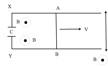
Ans. The induced current in the loop is
$It{\text{ }} = {\text{ }}\dfrac{\varepsilon }{R}$
$It{\text{ }} = {\text{ }}\dfrac{1}{R}.\dfrac{d}{{dt{\text{ }}BA}}$
$It{\text{ }} = {\text{ }}\dfrac{{vBd}}{R}$
The angle formed by B and A is equal to zero.
Charge across the capacitor is $Q\left( t \right){\text{ }} = {\text{ }}Cv$
As the switch S is closed at t = 0
current across the capacitor =$I\left( c \right){\text{ }} = {\text{ }}\dfrac{{Q\left( t \right)}}{{RC}}$
We can compute the current across the circuit using the preceding information as
$I{\text{ }} = \dfrac{{BvdC}}{{RC{\text{ }}e{\;^{--t/RC}}}}$
30. For the arrangement B is constant and out of the paper, get the current in the sliding rod AB (resistance = R). There is no resistance in parallel cables. V is a constant value. At time t = 0, switch S is closed.
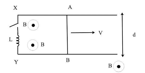
Ans: The angle formed by B and A is zero. Fleming's right hand rule directs I from point A to point B.
At t=0, switch S is closed.
The capacitor will be charged by the current from the first equation. Let Q(t) be the capacitor's charge.
As a result, the emf is Bvd.
$\dfrac{{ - LdI\left( t \right)}}{{dt}}{\text{ }} + {\text{ }}Bvd{\text{ }} = {\text{ }}IR$
$\dfrac{{LdI\left( t \right)}}{{dt}}{\text{ }} + {\text{ }}RI{\text{ }}\left( t \right){\text{ }} = {\text{ }}Bvd$
solving the equation, we get
$I{\text{ }} = {\text{ }}\dfrac{{Bvd}}{{R{\text{ }}[1 - {e^{ - Rt/2}}]}}$
31. In a location with a magnetic field, a metallic ring of mass m and radius l (ring being horizontal) is falling under gravity. The z-component of a magnetic field is ${B_z}\; = \;{B_o}\;\left( {{\bf{1}} + {\bf{\lambda }}\;z} \right)$if z is the vertical direction. Find the energy lost in the resistance if R is the ring's resistance and v is the ring's velocity.
Ans: Magnetic flux in an area with a magnetic field throughout a ring of mass'm' and radius 'l' falling under gravity$.{B_z} = {B_0}\left( {1 + \lambda z} \right){\text{ }}$
$.{B_z} = {B_0}\left( {1 + \lambda z} \right){\text{ }}$
$\phi = {B_z}A = {B_0}\left( {1 + \lambda z} \right){\text{ }}\pi {{\text{l}}^2}$
The angle between B and A is zero degree
$\varepsilon = \dfrac{d}{{dt}}[{B_0}\left( {1 + \lambda z} \right){\text{] }}\pi {{\text{l}}^2}$
$IR = {B_0}\pi {{\text{l}}^2}\left[ {0 + \lambda \dfrac{{dz}}{{dt}}} \right]$
$I = \dfrac{{{B_0}\pi {{\text{l}}^2}}}{R}\left[ {\dfrac{{dz}}{{dt}}} \right] = \dfrac{{{B_0}\pi {{\text{l}}^2}}}{R}v$
Loss in energy =$\dfrac{{{B_0}^2{\pi ^2}{\lambda ^2}{{\text{l}}^4}{v^2}}}{R}$
$v{\text{ }} = {\text{ }}\dfrac{{mgR}}{{B{0^2}{\pi ^2}{\lambda ^2}{l^4}}}$
32. A long solenoid 'S' with diameter 'a' has n turns per metre. A smaller coil with 'N' turns and diameter 'b' (where b a) is placed in the centre of this coil. What is the induced emf occurring in the smaller coil if the current in the solenoid grows linearly with time? If current fluctuates as a function of ${\bf{m}}{{\bf{t}}^2}{\text{ }} + {\text{ }}{\bf{C}}$, plot a graph to demonstrate the nature of the variation in emf.
Ans: The solenoid's fluctuating magnetic field is represented as:
${B_1}\left( t \right){\text{ }} = {\text{ }}\mu onI\left( t \right)$
The flux in the smaller coil is changed by the fluctuating magnetic field.
The second coil's magnetic flux is
${\Phi _2}{\text{ }} = {\text{ }}\mu onI\left( t \right).\pi {b^2}$
As a result of the solenoid's fluctuating magnetic field, the induced emf in the second coil is $\mu oNn{\text{ }}\pi {b^2}2mt{\text{ }}$.
NCERT Exemplar for Class 12 Physics - Electromagnetic Induction
Students appearing for the class 12 board examination or preparing for the graduate entrance examination at the national level will immensely benefit from the NCERT Exemplar for Class 12 Physics - Electromagnetic Induction provided by Vedantu.
Chapter 6 - Electromagnetic Induction is considered as one of the most crucial chapters a class 12 student can learn to score good marks in the class 12 board examination for physics.
This chapter is made up of various concepts that are important for a class 12 student to understand:
Introduction of Electricity and Magnetism
The Experiments of Faraday and Henry
Magic Flux
Faraday's Law of Induction
Lenz's Law and Conservation of Energy
Emotional Electromotive Force
Energy Consideration: A Quantitative Study
Eddy Currents
Inductance
AC Generator
Students of class 12 are expected to acquire a deeper understanding of these concepts to score good marks in the Class 12 board examination for Physics. And one of the best ways to do that is by studying Vednatu's NCERT Exemplar for Class 12 Physics - Electromagnetic Induction.

FAQs on NCERT Exemplar for Class 12 Physics - Electromagnetic Induction - Free PDF Download
1. Is Vedantu's NCERT Exemplar for Class 12 Physics Chapter 6 - Electromagnetic Induction precise?
Yes. Talking about the relevancy of Vedantu's NCERT Exemplar for Class 12 Physics - Electromagnetic Induction, the quality of solutions students can get from it is guaranteed. That is because these solutions are prepared by physics experts working at Vedantu who have thorough and relevant experience in this field. Students can directly download this study material and start reading as it is available in a PDF format completely free of cost. Students of class 12 can also check out Vedantu's NCERT Exemplars for class 12 for all subjects on Vedantu's website. Or they can download Vedantu App for more convenience.
2. What topics are covered in Vedantu's NCERT Exemplar for Class 12 Physics Chapter 6 - Electromagnetic Induction?
Chapter 6 - Electromagnetic Induction is looked upon as one of the most important chapters in class 12 physics from the examination point of view. There are numerous topics like Introduction of Electricity and Magnetism, The Experiments of Faraday and Henry, Magic Flux and much more in chapter 6. And Vedantu's NCERT Exemplar for Class 12 Physics Chapter 6 - Electromagnetic Induction covers all of them. To put it simply, no important topic is ignored by Vedantu physics experts while creating this study material.
3. Is the Class 12 Physics Chapter 6 - Electromagnetic Induction crucial?
The short answer is Yes. The class 12 physics chapter 6 - Electromagnetic Induction is extremely important from the examination point of view. Students are expected to learn this chapter thoroughly as it contains some highly crucial topics. That is why experts at Vedantu have performed thorough research on Class 12 Physics Chapter 6 - Electromagnetic Induction and created the NCERT Exemplar for Class 12 Physics Chapter 6 - Electromagnetic Induction. Class 12 students will benefit from this precisely created study material.
4. How to use Vedantu's NCERT Exemplar for Class 12 Physics Chapter 6 - Electromagnetic Induction?
Students of class 12 are expected to use Vedantu's NCERT Exemplar for Class 12 Physics Chapter 6 - Electromagnetic Induction like a citation when studying chapter 6 (Electromagnetic Induction) problems. Also, class 12 students must get a deeper understanding of the pattern that is acceptable and desirable by the CBSE board from the examination point of view. By taking full advantage of this study material, class 12 students have a higher chance of scoring good marks in the class 12 physics examination.
5. How many questions are solved in Vedantu's NCERT Exemplar for Class 12 Physics Chapter 6 - Electromagnetic Induction?
Vedantu's NCERT Exemplar for Class 12 Physics Chapter 6 - Electromagnetic Induction contains all of the 32 questions that are provided in the exercise part of the chapter. These questions are thoroughly solved by the physics experts working at Vedantu. These experts are highly qualified and have deeper insights on the topic. They also possess a thorough knowledge of the CBSE paper pattern and marking scheme. Students can benefit from the expertise of these experts by studying the solutions provided by them.