


Free PDF Download of Solutions Available on Vedantu
MULTIPLE CHOICE QUESTIONS-1
1. If the rms current in a \[50\] Hz ac circuit is $5$ A, the value of the current $\dfrac{1}{{300}}$ seconds after its value becomes zero is:
a) $5\sqrt 2 A$
b) \[5\sqrt {\dfrac{3}{2}} A\]
c) $\dfrac{5}{6}A$
d) $\dfrac{5}{{\sqrt 2 }}A$
Ans: Option b
We are given ${I_{rms}} = 5A$.
We know that ${I_{rms}} = \dfrac{{{I_0}}}{{\sqrt 2 }} = 5A$
$ \Rightarrow {I_0} = 5\sqrt 2 A$
Now, $I = {I_0}\sin \omega t = {I_0}\sin 2\pi \nu t$.
Substituting the known values at $t = \dfrac{1}{{300}}s$, we get,
$ \Rightarrow I = 5\sqrt 2 \sin \left[ {2\pi \left( {50} \right)\left( {\dfrac{1}{{300}}} \right)} \right]$
$ \Rightarrow I = 5\sqrt 2 \sin \left( {\dfrac{\pi }{3}} \right)$
Putting the value of sine, we get,
$ \Rightarrow I = 5\sqrt {\dfrac{3}{2}} A$
Hence, option (b) is the correct answer.
2. An alternating current generator has an internal resistance \[{R_g}\]and an internal reactance \[{X_g}\] . It is used to supply power to a passive load consisting of a resistance \[{R_g}\] and a reactance \[{X_L}\]. For maximum power to be delivered from the generator to the load, the value of \[{X_L}\] is equal to:
a) zero
b) \[{X_g}\]
c) \[ - {X_g}\]
d) \[{R_g}\]
Ans: Option c
We are given that the internal resistance of the generator is equal to the external resistance of the circuit \[{R_g}\]. For maximum power to be delivered from the generator to the load, the internal reactance of the generator should be equal to the reactance in the external circuit. Hence, the value of \[{X_L}\] is equal to \[ - {X_g}\]. Therefore, option (c) is the correct answer.
3. When a voltage measuring device is connected to AC mains, the meter shows the steady input voltage of\[220V\]. This means:
(a) input voltage cannot be AC voltage, but a DC voltage.
(b) maximum input voltage is \[200V\].
(c) the meter reads not$\nu $ but$\left\langle {{\nu ^2}} \right\rangle $ and is calibrated to read $\sqrt {\left\langle {{\nu ^2}} \right\rangle } $.
(d) the pointer of the meter is stuck by some mechanical defect.
Ans: Option d
The voltmeter in the AC circuit reads the value as $\sqrt {\left\langle {{\nu ^2}} \right\rangle } $ and the meter, on the other hand, is calibrated to rms value $\left\langle {{\nu ^2}} \right\rangle $ which is multiplied by $\sqrt 2 $ to get ${\nu _{rms}}$.
4. To reduce the resonant frequency in an LCR series circuit with a generator
(a) the generator frequency should be reduced.
(b) another capacitor should be added in parallel to the first.
(c) the iron core of the inductor should be removed.
(d) dielectric in the capacitor should be removed.
Ans: Option b
The formula for resonant frequency is ${\nu _0} = \dfrac{1}{{2\pi \sqrt {LC} }}$. So, to reduce the resonant frequency, we have to increase the capacitance of inductance. Capacitance can be increased by adding another capacitor in parallel to the first one. Hence, option (b) is the correct answer.
5. Which of the following combinations should be selected for better tuning of an LCR circuit used for communication?
a) $R = 20\Omega $, $L = 1.5H$, $C = 35\mu F$
b)$R = 25\Omega $, $L = 2.5H$, $C = 45\mu F$
c)$R = 15\Omega $, $L = 3.5H$, $C = 30\mu F$
d) $R = 25\Omega $, $L = 1.5H$, $C = 45\mu F$
Ans: Option c
The quality factor should be higher for better communication. We know the formula for quality factor as $Q = \dfrac{1}{R}\sqrt {\dfrac{L}{C}} $.
So, for higher Q, L has to be large and value of C and R have to be small.
This is satisfied in option c. Hence, option (c) is the correct answer.
6. An inductor of reactance \[1\Omega \] and a resistor of \[2\Omega \] are connected in series to the terminals of a \[6V\](rms) a.c. source. The power dissipated in the circuit is:
a) $8W$
b) $12W$
c) $14.4W$
d) $18W$
Ans: Option c
Formula for average power is${P_{av}} = {E_{rms}}{I_{rms}}\cos \phi $.
Now, $Z = \sqrt {{X_R}^2 + {X_L}^2} = \sqrt {{2^2} + {1^2}} = \sqrt 5 $
So, ${I_{rms}} = \dfrac{{{E_{rms}}}}{Z} = \dfrac{6}{{\sqrt 5 }}$
$\cos \phi = \dfrac{R}{Z} = \dfrac{2}{{\sqrt 5 }}$
Substituting the known values in the formula for average power.
${P_{av}} = \left( 6 \right)\left( {\dfrac{6}{{\sqrt 5 }}} \right)\left( {\dfrac{2}{{\sqrt 5 }}} \right) = \dfrac{{72}}{5} = 14.4W$
7. The output of a step-down transformer is measured to be \[24\] V when connected to a \[12\]watt light bulb. The value of the peak current is
a) $\dfrac{1}{{\sqrt 2 }}A$
b) $\sqrt 2 A$
c) $2A$
d) \[2\sqrt 2 A\]
Ans: Option a
So, we are given the rms value of voltage as \[24\].
Now, Power \[ = {V_{rms}} \times {I_{rms}} = 12W\].
So, we get,
\[ \Rightarrow 24 \times {I_{rms}} = 12\]
\[ \Rightarrow {I_{rms}} = \dfrac{1}{2}\]
Now, the peak value of current $ = {I_0} = \sqrt 2 {I_{rms}}$
$ \Rightarrow {I_0} = \sqrt 2 \left( {\dfrac{1}{2}A} \right)$
$ \Rightarrow {I_0} = \dfrac{1}{{\sqrt 2 }}A$
MULTIPLE CHOICE QUESTIONS-II
MORE THAN ONE OPTION
8. As the frequency of an AC circuit increases, the current first increases and then decreases. What combination of circuit elements is most likely to comprise the circuit?
(a) Inductor and capacitor.
(b) Resistor and inductor.
(c) Resistor and capacitor.
(d) Resistor, inductor and capacitor
Ans: The current in a circuit will be maximum when the reactance will be minimum.
The formula for impedance in LCR circuit is $Z = \sqrt {{R^2} + {{\left( {{X_L} - {X_C}} \right)}^2}} $. So, ${X_L}$ should be equal to ${X_C}$ for reactance or impedance to be minimum. So, an inductor and capacitor must be in a circuit. Hence, options (a) and (d) are the correct answers.
9. In an alternating current circuit consisting of elements in series, the current increases on increasing the frequency of supply. Which of the following elements are likely to constitute the circuit?
(a) Only resistor.
(b) Resistor and an inductor.
(c) Resistor and a capacitor.
(d) Only a capacitor.
Ans: It is given in the question that the current increases on increasing the frequency of the supply. We know that resistance does not depend upon frequency and capacitive reactance of a circuit decreases with time. So, ${X_C}$ decreases to increase the current in the circuit. Hence, options (c) and (d) are correct.
10. Electrical energy is transmitted over large distances at high alternating voltages. Which of the following statements is (are) correct?
(a) For a given power level, there is a lower current.
(b) Lower current implies less power loss.
(c) Transmission lines can be made thinner.
(d) It is easy to reduce the voltage at the receiving end using step-down transformers.
Ans: options (a), (b) and (d) are correct
We know the formula \[P = {V_{rms}} \times {I_{rms}} = {\left( {{I_{rms}}} \right)^2}R\]. So, to reduce the power loss, \[{I_{rms}}\] and R must be lower. To decrease \[{I_{rms}}\], \[{V_{rms}}\] must be increased by a step up transformer so that the same power is derived from the step up transformer.
Now, ${V_s}{I_s} = {V_p}{I_p}$. Since, ${V_s} > {V_p}$. So, ${I_p} > > {I_s}$.
This makes the loss of power during transmission low. We reduce the voltage again by using a step down transformer.
Hence, options (a), (b) and (d) options are correct.
11. For an LCR circuit, the power transferred from the driving source to the driven oscillator is $P = {I^2}Z\cos \phi $.
a) Here, the power factor $\cos \phi \geqslant 0$ and $P \geqslant 0$
b) The driving force can give no energy to the oscillator $P = 0$ in some cases.
c) The driving force cannot syphon out $P < 0$ the energy out of the oscillator.
d) The driving force can take away energy out of the oscillator.
Ans: We are given that $P = {I^2}Z\cos \phi $.
The power factor $\cos \phi $ is equal to $\left( {\dfrac{R}{Z}} \right)$. Since R and Z are both non-negative.
So, $\cos \phi = \left( {\dfrac{R}{Z}} \right) \geqslant 0$
Therefore, the power factor $\cos \phi \geqslant 0$ and $P \geqslant 0$.
Also, $P = 0$ in some cases where $\cos \phi = \left( {\dfrac{R}{Z}} \right) = 0$. But $P < 0$ is not possible since the expression ${I^2}Z\cos \phi $ cannot be negative.
12. When an AC voltage of $220$ V is applied to the capacitor C,
(a) The maximum voltage between plates is $220$ V.
(b) the current is in phase with the applied voltage.
(c) the charge on the plates is in phase with the applied voltage.
(d) power delivered to the capacitor is zero.
Ans: The plate of capacitor connected to the positive terminal will be at a higher potential than the plate which is connected at a lower potential.

Now, the formula for power applied to the circuit is \[P = {V_{rms}}{I_{rms}}\cos \phi \]. Now, \[\phi \] for a purely capacitive circuit is equal to \[{90^ \circ }\].
Hence, \[P = {V_{rms}}{I_{rms}}\cos {90^ \circ } = 0\]. Therefore, options (c) and (d) are the correct answers.
13. The line that draws power supply to your house from street has
(a) zero average current.
(b) $220$ V average voltage.
(c) voltage and current out of phase by \[{90^ \circ }\].
(d) voltage and current possibly differing in phase such that $\left| \phi \right| < \dfrac{\pi }{2}$.
Ans: In Household circuits, capacitors and inductors are connected. So, the impedance of the circuit cannot be equal to the resistance.
So, Power factor is $\cos \phi = \dfrac{R}{Z} \ne 0$
So, $\phi \ne \dfrac{\pi }{2}$. Hence, $\phi < \dfrac{\pi }{2}$.
Also, the average current value over a cycle of AC is zero.
Therefore, options (a) and (d) are correct choices.
VERY SHORT ANSWER TYPE QUESTIONS
14. If a L-C circuit is considered analogous to a harmonically oscillating spring block system, which energy of the L-C circuit would be analogous to potential energy and which one analogous to kinetic energy?
Ans: If we consider a LC circuit to be analogous to a harmonically oscillating spring block system, then the energy due to motion of the charged particles which refers to the magnetic energy $\dfrac{1}{2}L{I^2}$ is analogous to the kinetic energy. The potential energy is analogous to the electrostatic energy due to the charging of capacitor $\dfrac{1}{2}C{V^2}$.
15. Draw the effective equivalent circuit of the circuit shown in Fig 7.1, at very high frequencies and find the effective impedance.

Ans: As frequency is very high and we know that inductance is equal to ${X_L} = 2\pi \nu L$. So, the inductor can be considered as open circuit. Similarly, ${X_C} = \dfrac{1}{{2\pi \nu C}}$. So at high frequencies, ${X_C}$ will be very low. So, reactance of capacitance is considered as negligible and capacitor can be considered as short circuited.
So, we get the circuit as below:

Now, simplifying the circuit further, we get,

So, the total impedance of the circuit $ = Z = {R_1} + {R_3}$.
16. Study the circuits (a) and (b) shown in Fig 7.2 and answer the following questions. Fig. 7.2

(a) Under which conditions would the rms currents in the two circuits be the same?
Ans: So, we have to calculate the rms currents in both circuits.
\[{I_{rms}}\] in circuit (a) \[ = \dfrac{{{V_{rms}}}}{R}\]
\[{I_{rms}}\] in circuit (b) \[ = \dfrac{{{V_{rms}}}}{Z}\] where $Z = \sqrt {{R^2} + {{\left( {{X_L} - {X_C}} \right)}^2}} $
So, \[{I_{rms}} = \dfrac{{{V_{rms}}}}{{\sqrt {{R^2} + {{\left( {{X_L} - {X_C}} \right)}^2}} }}\]
Equating the values of rms currents in both circuits. So, we ge,
\[{R^2} + {\left( {{X_L} - {X_C}} \right)^2} = {R^2}\]
\[ \Rightarrow {X_L} = {X_C}\]
Hence, rms currents in the two circuits are the same if \[{X_L} = {X_C}\].
(b) Can the rms current in circuit (b) be larger than that in (a)?
Ans: So, we have, \[\dfrac{{{V_{rms}}}}{{\sqrt {{R^2} + {{\left( {{X_L} - {X_C}} \right)}^2}} }} > \dfrac{{{V_{rms}}}}{R}\].
\[ \Rightarrow \sqrt {{R^2} + {{\left( {{X_L} - {X_C}} \right)}^2}} < R\]
Squaring both sides, we get,
\[ \Rightarrow {R^2} + {\left( {{X_L} - {X_C}} \right)^2} < {R^2}\]
\[ \Rightarrow {\left( {{X_L} - {X_C}} \right)^2} < 0\]
Since the square of any number cannot be negative. So, this is not possible.
Hence, rms current in circuit (b) cannot be larger than that in (a).
17. Can the instantaneous power output of an ac source ever be negative? Can the average power output be negative?
Ans: Let us suppose the emf to be $E = {E_0}\sin \left( {\omega t} \right)$
Let the phase difference in current and emf be $\phi $.
$I = {I_0}\sin \left( {\omega t - \phi } \right)$
Now, power $ = P = {E_0}{I_0}\sin \left( {\omega t - \phi } \right)\sin \left( {\omega t} \right)$
Expanding the sine of difference of two angles,
$ \Rightarrow P = {E_0}{I_0}\left( {\sin \left( {\omega t} \right)\cos \phi - \cos \left( {\omega t} \right)\sin \phi } \right)\sin \left( {\omega t} \right)$
$ \Rightarrow P = {E_0}{I_0}\left( {{{\sin }^2}\left( {\omega t} \right)\cos \phi - \sin \left( {\omega t} \right)\cos \left( {\omega t} \right)\sin \phi } \right)$
$ \Rightarrow P = {E_0}{I_0}\left( {\dfrac{{1 - \cos \left( {2\omega t} \right)}}{2}\cos \phi - \dfrac{1}{2}\sin \left( {2\omega t} \right)\sin \phi } \right)$
\[ \Rightarrow P = \dfrac{{{E_0}{I_0}}}{2}\left( {\cos \phi - \cos \left( {2\omega t} \right)\cos \phi - \sin \left( {2\omega t} \right)\sin \phi } \right)\]
\[ \Rightarrow P = \dfrac{{{E_0}{I_0}}}{2}\left( {\cos \phi - \left( {\cos \left( {2\omega t} \right)\cos \phi + \sin \left( {2\omega t} \right)\sin \phi } \right)} \right)\]
\[ \Rightarrow P = \dfrac{{{E_0}{I_0}}}{2}\left( {\cos \phi - \cos \left( {2\omega t - \phi } \right)} \right)\]
So, instantaneous power \[P = \dfrac{{{E_0}{I_0}}}{2}\left( {\cos \phi - \cos \left( {2\omega t - \phi } \right)} \right)\] as \[\cos \phi = \dfrac{R}{Z}\] where R and Z can never be negative. Also, the value of \[\cos \left( {2\omega t - \phi } \right)\] can vary between $ - 1$ to $1$. Hence, P cannot be negative in any case.
Also, average power $ = {P_{av}} = \dfrac{{{E_0}{I_0}}}{2}\cos \phi $.
Since \[\cos \phi = \dfrac{R}{Z}\] is positive. So, ${P_{av}}$ can never be positive.
18. In the series LCR circuit, the plot of \[{\operatorname{I} _{\max }}\,vs\,\omega \] is shown in Fig 7.3. Find the bandwidth and mark in the figure.

Ans: We know that bandwidth $\left( {{\omega _2} - {\omega _1}} \right)$, where ${\omega _1}$ and ${\omega _2}$ are two frequencies where the current amplitude of LCR circuit becomes $\dfrac{1}{{\sqrt 2 }}$ times, the value of current is maximum at resonant frequency.
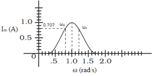
$I = \dfrac{{{E_0}}}{{\sqrt 2 }} = \dfrac{1}{{\sqrt 2 }} = 0.707A$
From the graph, we have two frequencies ${\omega _1}$ and ${\omega _2}$ for which current is $0.707A$ as ${\omega _1} = 0.8\dfrac{{rad}}{s}$and${\omega _2} = 1.2\dfrac{{rad}}{s}$.
Therefore, ${\omega _2} - {\omega _1} = 0.4\dfrac{{rad}}{s}$
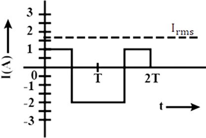
19. The alternating current in a circuit is described by the graph shown in Fig 7.4. Show rms current in this graph.

Ans: ${I_{rms}} = \sqrt {\dfrac{{{1^2} + {2^2}}}{2}} = \sqrt {\dfrac{5}{2}} = 1.6A$ (approximately)
Hence, the graph showing rms current is shown below by dotted line:
20. How does the sign of the phase angle $\phi $, by which the supply voltage leads the current in an LCR series circuit, change as the supply frequency is gradually increased from very low to very high values.
Ans:The phase angle by which voltage leads the current in LCR circuit is $\phi $.
Now, ${X_L} > {X_C}$.
So, \[\tan \phi = \dfrac{{{X_L} - {X_C}}}{R}\]
Putting the values of \[{X_C}\] and \[{X_L}\], we get,
\[\tan \phi = \dfrac{{2\pi \nu L - \dfrac{1}{{2\pi \nu C}}}}{R}\]
If \[\nu \] is small, \[{X_C} > {X_L}\]. So, \[\left( {2\pi \nu L - \dfrac{1}{{2\pi \nu C}}} \right)\] is negative. So, \[\tan \phi < 0\].
Now, for larger \[\nu \], we have, \[{X_L} > {X_C}\]. So, \[{X_L} - {X_C}\] is positive. Hence, the phase angle $\phi $ changes from negative to zero and then zero to positive.
SHORT ANSWER TYPE QUESTIONS
7.21 A device ‘X’ is connected to an a.c source. The variation of voltage, current and power in one complete cycle is shown in Fig 7.5.

(a) Which curve shows power consumption over a full cycle?
Ans: Because P=VI, the power amplitude will be equal to the multiplication of V and I, hence it must be the highest amplitude when compared to V and I. As a result, curve A depicts the power use throughout the course of a cycle. When either V=0 or I=0, or both, the power of a circuit will be zero, as shown in graph 'A is zero (on dotted lines) at these places.
(b) What is the average power consumption over a cycle?
Ans. A represents the graph of power. The graph 'A' is symmetric with respect to the X-axis, which means that the area of the graph on the positive and negative sides is equal. As a result, the net area of the power graph is zero. As a result, the circuit's power consumption is zero, which corresponds to the average power of an A.C. circuit across a cycle being zero.
(c) Identify the device ‘X’.
Ans. The average power of the device sums up to zero. The power factor will be given by $cos\varphi = 0$ that is $\varphi = 9{0^o}$ . Either an inductor or a capacitor may change the phase of current and voltage. As a result, the device can be either a capacitor or an inductor, or a blend of both.
7.22 Both alternating current and direct current are measured in amperes. But how is the ampere defined for an alternating current?
Ans:'One Ampere' is equal to one coulomb charge flowing every second in direct current. Current switches direction in an AC at a time equal to half of the AC's time period. As a result, the charge vibrates back and forth at the same frequency as AC. As a result, the charge's net force is zero. As a result, the AC current in ampere must be described in terms of a characteristic that is independent of charge or current direction. Such a feature is Joule's heating effect, which is why Joule's heating rule is used to describe one ampere current in AC. One ampere current in AC is the current that may create the same amount of heat per second as direct current in a one-ohm resistance, according to Joule's heating effect.
7.23 A coil of 0.01 henry inductance and 1 ohm resistance is connected to 200 volt, 50 Hz ac supply. Find the impedance of the circuit and time lag between maximum alternating voltage and current.

Impedance of the circuit
Ans:Given:
\[R = 1\Omega \] , L=0.01H, V=200 V, v=50 Hz
$Z = \sqrt {{R^2} + {X_L}^2} = \sqrt {{R^2} + \left( {2\pi \nu {L^2}} \right)} $
$ = \sqrt {{{\left( 1 \right)}^2} + {{\left( {2 \times 3.14 \times 50 \times 0.01} \right)}^2}} $
$ = \sqrt {1 + 9.86} $
$ = \sqrt {10.86} $
$ = 3.3\Omega $
Now,
Phase angle is the ratio of Z to R.
\[\tan \phi = \dfrac{Z}{R}\]
\[\tan \phi = \dfrac{{{X_L}}}{R} = \dfrac{{2\pi vL}}{R} = \dfrac{{2 \times 3.14 \times 50 \times 0.01}}{1} = 3.14\]
\[\phi = {\tan ^{ - 1}}3.14 = {72^o}\]
\[\phi = \dfrac{{72 \times \pi }}{{{{180}^o}}}rad = 1.20radian\]
The time lag between alternating voltage and current is given by
\[\phi = \omega t\]
\[t = \dfrac{\phi }{\omega } = \dfrac{{72 \times \pi }}{{180 \times \pi \times 2 \times 50}} = \dfrac{1}{{250}}\sec \]
7.24. A 60 W load is connected to the secondary of a transformer whose primary draws line voltage. If a current of 0.54 A flows in the load, what is the current in the primary coil? Comment on the type of transformer being used.
Ans: Given: \[{P_S} = 60W\] , \[{I_S} = 0.54A\]
\[{P_S} = {I_S} \times {V_S}\]
\[{V_S} = \dfrac{{{P_S}}}{{{I_S}}}\]
\[{V_S} = \dfrac{{60W}}{{0.54A}} = 111.10Volt\]
It will approximately be equal to,
\[{V_S} \approx 110Volt\]
Now,
Ratio factor of transformer (r) = \[\dfrac{{Output\,voltage}}{{Input\,voltage}} = \dfrac{{{V_s}}}{{{V_P}}} = \dfrac{{110V}}{{220V}} = \dfrac{1}{2} = 0.5\]
As ‘r’ is less than 1, the transformer is a stepdown transformer.
In this transformer Output power is equal to input power.
\[\therefore {I_S}{V_S} = {I_P}{V_P}\]
\[\therefore {I_P} = \dfrac{{{I_S}{V_S}}}{{{V_P}}} = \dfrac{{0.54 \times 110}}{{220}} = 0.27A\]
The input power = 0.27A.
7.25 Explain why the reactance provided by a capacitor to an alternating current decreases with increasing frequency.
Ans: When an alternating current (AC) is applied over a capacitor plate, the plates charge and discharge periodically. The charging and discharging of the capacitor by AC voltage or current results in current flowing through the capacitor. A capacitor will not enable a zero-frequency direct current to flow from it. However, if the frequency of current rises, the capacitor will transfer more current through it, as charging and discharging occurs at a faster pace. It means that when the frequency increases, the capacitor's reactance drops.
Thus, the reactance of capacitor is given by ${X_c} = \dfrac{1}{{\omega C}}$
7.26 Explain why the reactance offered by an inductor increases with increasing frequency of an alternating voltage.
Ans: When the current inside an inductor changes, the direction of induced e.m.f. opposes the change in current in the inductor, as per Lenz's law. The magnetic flux created by altering the e.m.f. or current in the coil will be in the reverse direction, and vice versa. An inductor generates increased reactance to current flow because the induced e.m.f is exactly proportional to the rate of change of current. When a direct current runs through an inductor, the inductor's reactance is zero.
As a result, when an AC current is applied, the reactance grows as the frequency of the AC increases. So, the reactance and the frequency are in direct proportion with each other. Thus, the reactance of the inductor is given by ${X_L} = 2\pi vL = \omega L$.
LONG ANSWER TYPE QUESTIONS
7.27 An electrical device draws 2kW power from AC mains [Voltage 223V (rms) = $\sqrt {50000} V$ ]. The current differs (lags) in phase by \[\left( {\tan \phi = \dfrac{{ - 3}}{4}} \right)\] as compared to voltage. Find (i) R, (ii) \[{X_C}--{X_L}\] and (iii) ${I_M}$. Another device has twice the values for R, \[{X_C}\,{\text{and}}\,{X_L}\]. How are the answers affected?
Ans: Power = 2000W
V= $\sqrt {50000} V$
$\therefore {V^2} = 50000V$
Now,
$P = \dfrac{{{V^2}}}{Z}$
$Z = \dfrac{{{V^2}}}{P} = \dfrac{{50000}}{{2000}} = 25\Omega $
\[Z = \sqrt {{R^2} + {{\left( {{X_C}--{X_L}} \right)}^2}} \]
\[25 = \sqrt {{R^2} + {{\left( {{X_C}--{X_L}} \right)}^2}} \]
\[{\left( {25} \right)^2} = {R^2} + {\left( {{X_C}--{X_L}} \right)^2}\]
\[{R^2} + {\left( {{X_C}--{X_L}} \right)^2} = 625\] (i)
Now,
\[\left( {\tan \phi = \dfrac{{ - 3}}{4}} \right)\]
\[\dfrac{{{X_C}--{X_L}}}{R} = \dfrac{{ - 3}}{4}\]
\[{X_C}--{X_L} = \dfrac{{ - 3}}{4}R\]
\[{\left( {{X_C}--{X_L}} \right)^2} = {\left( {\dfrac{{ - 3}}{4}R} \right)^2} = \dfrac{9}{{16}}{R^2}\] (ii)
From (i) and (ii) we get,
\[625 = \dfrac{9}{{16}}{R^2} + {R^2}\]
\[625 = \dfrac{{25}}{{16}}{R^2}\]
$\therefore R = 25\Omega $
Also,
\[{X_C}--{X_L} = \dfrac{{ - 3}}{4}R = \dfrac{{ - 3}}{4} \times 20 = 15\Omega \]
${I_{rms}} = \dfrac{V}{Z} = \dfrac{{223}}{{25}} = 8.92 \approx 9A$
${I_o} = \sqrt 2 {I_{rms}} = \sqrt 2 \times 9 = 1.44 \times 9 = 12.96A$
For another device if
(i) R, \[{X_C}\] and \[{X_L}\] are doubled then, \[\tan \phi \] remains the same.
(ii) Z is doubled; the current will be half its value as V remains unchanged.
(iii) Power will be halved if the current also is reduced to half.
7.28 1MW power is to be delivered from a power station to a town 10 km away. One uses a pair of Cu wires of radius 0.5 cm for this purpose. Calculate the fraction of ohmic losses to power transmitted if
(i) power is transmitted at 220V. Comment on the feasibility of doing this.
Ans. Given: \[{\rho _{Cu}}{\text{ = 1}}{\text{.7}} \times {10^{ - 8}}{\text{SI}}\,{\text{unit }}\]
Resistance = $\dfrac{{\rho l}}{A} = \dfrac{{\rho l}}{{\pi {r^2}}} = \dfrac{{1.7 \times {{10}^{ - 8}} \times 20000m}}{{3.14 \times {{\left( {5 \times {{10}^{ - 3}}m} \right)}^2}}} = \dfrac{{170 \times 800}}{{314 \times 100}} = \dfrac{{680}}{{157}} = 4.33 \approx 4\Omega $
Now,
Power loss = ${I^2}R = {\left( {\dfrac{P}{V}} \right)^2}R = \left( {\dfrac{{1000000}}{{220}}} \right) \times 4 = \dfrac{{50000}}{{11}} \times 4 = 8.26 \times {10^7}MW$
Power loss is greater than 1 $\left( {8.26 \times {{10}^7} > 1} \right)$
So, this method is not correct to transfer the power.
(ii) a step-up transformer is used to boost the voltage to 11000 V, power transmitted, then a step-down transformer is used to bring voltage to 220 V. (\[{\rho _{Cu}}{\text{ = 1}}{\text{.7}} \times {10^{ - 8}}{\text{SI}}\,{\text{unit }}\])
Ans. When transmission of power is at V = 11000V
P = VI
Here,
P= 1000000W
$I = \dfrac{P}{V} = \dfrac{{1000000}}{{11000}} = \dfrac{{1000}}{{11}}$
Power loss = ${I^2}R = {\left( {\dfrac{P}{V}} \right)^2}R = {\left( {\dfrac{{1000}}{{11}}} \right)^2} \times 4 = \dfrac{{40000}}{{121}} \times 4 = 3.3 \times {10^4}W$
Fractional power loss = $\dfrac{{3.3 \times {{10}^4}W}}{{{{10}^6}}} = 0.033$
Power loss in percent = 3.3%.
7.29 Consider the LCR circuit shown in Fig 7.6. Find the net current i and the phase of i. Show that $I = \dfrac{V}{Z}$. Find the impedance Z for this circuit.
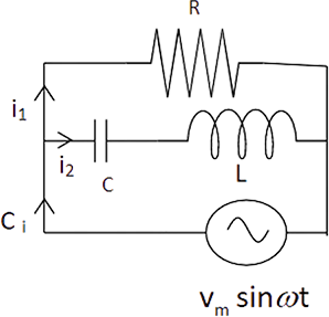
Ans: Total current $i$ from the source ${V_m}\sin \omega t$ is divided at B in two parts. Part ${i_1}$ current through capacitor and inductor and part ${i_2}$ current through resistance.
Potential across R = Potential of source
Potential difference across R = ${V_m}\sin \omega t$
$ \Rightarrow {i_2}R = {V_m}\sin \omega t$
$ \Rightarrow {i_2} = \dfrac{{{V_m}\sin \omega t}}{R}......\left( i \right)$

${q_1}$ is charged on the capacitor at any time $t$, then for series combination of C, L applying Kirchhoff’s voltage law in loop ABEFA.
$ \Rightarrow {V_C} + {V_L} = {V_m}\sin \omega t$
$ \Rightarrow \dfrac{{{q_1}}}{C} + L\dfrac{{d{i_1}}}{{dt}} = {V_m}\sin \omega t$
$ \Rightarrow \dfrac{{{q_1}}}{C} + L\dfrac{{{d^2}{q_1}}}{{d{t^2}}} = {V_m}\sin \omega t......\left( {ii} \right)$
Let ${q_1} = {q_m}\sin \left( {\omega t + \phi } \right)........\left( {iii} \right)$
$ \Rightarrow i = \dfrac{{d{q_1}}}{{dt}}{q_m}\omega \cos \left( {\omega t + \phi } \right)..........\left( {iv} \right)$
$\dfrac{{{d^2}{q_1}}}{{d{t^2}}} = - {q_m}{\omega ^2}\sin \left( {\omega t + \phi } \right)......\left( v \right)$
Now, substitute the values of equations $\left( {iii} \right)$ and $\left( v \right)$ in equation $\left( {ii} \right)$
$ \Rightarrow \dfrac{{{q_m}\sin \left( {\omega t + \phi } \right)}}{C} - L{q_m}{\omega ^2}\sin \left( {\omega t + \phi } \right) = {V_m}\sin \omega t$
$ \Rightarrow {q_m}\sin \left( {\omega t + \phi } \right)\left[ {\dfrac{1}{C} - L{\omega ^2}} \right] = {V_m}\sin \omega t$
At $\phi = 0$,
$ \Rightarrow {q_m}\sin \left( {\omega t + 0} \right)\left[ {\dfrac{1}{C} - L{\omega ^2}} \right] = {V_m}\sin \omega t$
$ \Rightarrow {q_m}\left[ {\dfrac{1}{C} - L{\omega ^2}} \right]\sin \omega t = {V_m}\sin \omega t$
$ \Rightarrow {q_m}\left[ {\dfrac{1}{C} - L{\omega ^2}} \right] = {V_m}$
$ \Rightarrow {q_m} = \dfrac{{{V_m}}}{{\left[ {\dfrac{1}{C} - L{\omega ^2}} \right]}}..........\left( {vi} \right)$
Now, we will apply Kirchhoff’s junction rule at junction B, $i = {i_2} + {i_1}$ using relation $\left( i \right)$, $\left( {iv} \right)$.
$ \Rightarrow i = \dfrac{{{V_m}\sin \omega t}}{R} + {q_m}\omega \cos \left( {\omega t + \phi } \right)$
Now, using relation $\left( {vi} \right)$ from ${q_m}$ and at $\phi = 0$, we get
$ \Rightarrow i = \dfrac{{{V_m}\sin \omega t}}{R} + \dfrac{{{V_m}\omega \cos \omega t}}{{\omega \left[ {\dfrac{1}{{\omega C}} - L\omega } \right]}}$
$ \Rightarrow i = \dfrac{{{V_m}}}{R}\sin \omega t + \dfrac{{{V_m}}}{{\left[ {\dfrac{1}{{\omega C}} - L\omega } \right]}}\cos \omega t$
Let $A = \dfrac{{{V_m}}}{R} = C\cos \phi ......\left( {vii} \right)$
And, $B = \dfrac{{{V_m}}}{{\left[ {\dfrac{1}{{\omega C}} - L\omega } \right]}} = C\sin \phi ........\left( {viii} \right)$
$ \Rightarrow i = C\cos \phi \sin \omega t + C\sin \phi .\cos \omega t$
\[ \Rightarrow i = C\left( {\cos \phi .\sin \omega t + \sin \phi .\cos \omega t} \right)\]
\[ \Rightarrow i = C\sin \left( {\omega t + \phi } \right)\]
On squaring and adding $\left( {vii} \right)$ and $\left( {viii} \right)$, we get
\[ \Rightarrow {A^2} + {B^2} = {C^2}{\cos ^2}\phi + {C^2}{\sin ^2}\phi \]
\[ \Rightarrow {A^2} + {B^2} = {C^2}\left( {{{\cos }^2}\phi + {{\sin }^2}\phi } \right)\]
\[ \Rightarrow {A^2} + {B^2} = {C^2}\]
\[ \Rightarrow C = \sqrt {{A^2} + {B^2}} \]
$\therefore \phi = {\tan ^{ - 1}}\dfrac{B}{A} = {\tan ^{ - 1}}\dfrac{{\dfrac{{{V_m}}}{{\left[ {\dfrac{1}{{\omega C}} - L\omega } \right]}}}}{{\dfrac{{{V_m}}}{R}}}$
$ \Rightarrow \phi = {\tan ^{ - 1}}\left( {\dfrac{1}{{\left[ {\dfrac{1}{{\omega C}} - L\omega } \right]}} \times \dfrac{R}{1}} \right)$
$\therefore \tan \phi = \dfrac{R}{{\left[ {\dfrac{1}{{\omega C}} - L\omega } \right]}}$
\[\because {C^2} = {A^2} + {B^2} = \dfrac{{V_m^2}}{{{R^2}}} + \dfrac{{V_m^2}}{{{{\left[ {\dfrac{1}{{\omega C}} - L\omega } \right]}^2}}}\]
\[ \Rightarrow C = {\left( {\dfrac{{V_m^2}}{{{R^2}}} + \dfrac{{V_m^2}}{{{{\left[ {\dfrac{1}{{\omega C}} - L\omega } \right]}^2}}}} \right)^{\dfrac{1}{2}}}\]
\[\therefore i = {\left( {\dfrac{{V_m^2}}{{{R^2}}} + \dfrac{{V_m^2}}{{{{\left[ {\dfrac{1}{{\omega C}} - L\omega } \right]}^2}}}} \right)^{\dfrac{1}{2}}}\sin \left( {\omega t + \phi } \right)\]
\[\therefore i = {V_m}{\left( {\dfrac{1}{{{R^2}}} + \dfrac{1}{{{{\left[ {\dfrac{1}{{\omega C}} - L\omega } \right]}^2}}}} \right)^{\dfrac{1}{2}}}\sin \left( {\omega t + \phi } \right)......\left( {ix} \right)\]
We have, $\phi = {\tan ^{ - 1}}\dfrac{R}{{\left[ {\dfrac{1}{{\omega C}} - L\omega } \right]}}$
$\because I = \dfrac{V}{R}$ or $i = \dfrac{V}{Z}$
For AC, $i = \dfrac{V}{Z}\sin \left( {\omega t + \phi } \right)......\left( x \right)$
On comparing $\left( {ix} \right)$ and $\left( x \right)$, we get
$ \Rightarrow \dfrac{1}{Z} = {\left( {\dfrac{1}{{{R^2}}} + \dfrac{1}{{{{\left[ {\dfrac{1}{{\omega C}} - L\omega } \right]}^2}}}} \right)^{\dfrac{1}{2}}}$
This is the impedance $Z$ for the circuit.
7.30 For an LCR circuit driven at frequency $\omega $, the equation reads $L\dfrac{{di}}{{dt}} + Ri + \dfrac{q}{C} = {V_i} = {V_m}\sin \omega t$.
(a) Multiply the equation by $i$ and simplify where possible.
Ans. Consider LCR series circuit with AC supply
$ \Rightarrow V = {V_m}\sin \omega t$
Applying voltage Kirchhoff’s law over the circuit
$\therefore {V_L} + {V_C} + {V_R} = {V_m}\sin \omega t$
Given, $L\dfrac{{di}}{{dt}} + Ri + \dfrac{q}{C} = {V_i} = {V_m}\sin \omega t$

Given that, $L\dfrac{{di}}{{dt}} + Ri + \dfrac{q}{C} = {V_i} = {V_m}\sin \omega t$
Multiply the above equation by $i$ on both the sides.
$ \Rightarrow Li\dfrac{{di}}{{dt}} + R{i^2} + i\dfrac{q}{C} = {V_m}i\sin \omega t$
Multiply the above equation by $\dfrac{1}{2}$ on both sides.
$ \Rightarrow \dfrac{1}{2}Li\dfrac{{di}}{{dt}} + \dfrac{1}{2}R{i^2} + i\dfrac{q}{{2C}} = \dfrac{1}{2}{V_m}i\sin \omega t$
We know that $i = \dfrac{{dq}}{{dt}}$. Therefore, we get.
$ \Rightarrow \dfrac{{d\left( {\dfrac{1}{2}L{i^2}} \right)}}{{dt}} + \dfrac{1}{{2C}}\dfrac{{d{q^2}}}{{dt}} + \dfrac{{R{i^2}}}{2} = \dfrac{1}{2}{V_m}i\sin \omega t.......\left( i \right)$
(b) Interpret each term physically.
Ans. (i) $\dfrac{{d\left( {\dfrac{1}{2}L{i^2}} \right)}}{{dt}}$ represents the rate of change of potential energy in inductance L.
(ii) $\dfrac{d}{{dt}}\dfrac{{{q^2}}}{{2C}}$ represents the energy stored in the capacitor in time $dt$.
(iii) ${i^2}R$ represents Joules heating loss.
(iv) $\dfrac{1}{2}{V_m}i\sin \omega t$ represents the rate at which the driving force pours in energy. It goes into ohmic loss and increase of stored energy in capacitor and inductor.
(c) Cast the equation in the form of a conservation of energy statement.
Ans. Here, equation $\left( i \right)$ is in the form of conservation of energy.
(d) Integrate the equation over one cycle to find that the phase difference between $\nu $ and $i$ must be acute.
Ans. On integrating the equation $\left( i \right)$ both sides with respect to $dt$ over a cycle, we get
$ \Rightarrow \int_0^T {\dfrac{{d\left( {\dfrac{1}{2}L{i^2}} \right)}}{{dt}}} dt + \int_0^T {\dfrac{{d{q^2}}}{{dt2C}}} dt + \int_0^T {\dfrac{{{i^2}R}}{2}} dt = \dfrac{1}{2}\int_0^T {{V_m}} i\sin \omega tdt$
$ \Rightarrow \int_0^T {\dfrac{d}{{dt}}\left[ {\dfrac{1}{2}L{i^2} + \dfrac{{{q^2}}}{{2C}}} \right]dt} + \dfrac{1}{2}\int_0^T {{i^2}R} dt = \dfrac{1}{2}\int_0^T V idt$
$ \Rightarrow 0 + \dfrac{1}{2}\int_0^T {{i^2}R} dt = \dfrac{1}{2}\int_0^T V idt$
$ \Rightarrow {i^2}RT = \int_0^T V idt$
We know that ${i^2}$, R and T can never be negative; it means ${i^2}RT$ is positive. So, $\int_0^T V idt$ is positive which is only possible if the phase difference $\phi $ is constant and the angle is acute.
7.31 In the LCR circuit shown in Fig 7.7, the ac driving voltage is $V = {V_m}\sin \omega t$.

(a) Write down the equation of motion for $q\left( t \right)$.
Ans: Consider LCR series circuit and tapping key K to short circuit R. Let the current in circuit be $i$. Then, by Kirchhoff’s voltage law, when key K is open,

$ \Rightarrow {V_R} + {V_L} + {V_C} = {V_m}\sin \omega t$
$iR + L\dfrac{{di\left( t \right)}}{{dt}} + \dfrac{{q\left( t \right)}}{C} - {V_m}\sin \omega t = 0$
As, charge $q\left( t \right)$ changes in circuit with time in AC, then $i = \dfrac{{dq\left( t \right)}}{{dt}}$
On differentiating, we get
$ \Rightarrow \dfrac{{di}}{{dt}} = \dfrac{{{d^2}q\left( t \right)}}{{d{t^2}}}$
$ \Rightarrow R\dfrac{{dq\left( t \right)}}{{dt}} + L\dfrac{{{d^2}q\left( t \right)}}{{d{t^2}}} + \dfrac{{q\left( t \right)}}{C} = {V_m}\sin \omega t$
$ \Rightarrow L\dfrac{{{d^2}q\left( t \right)}}{{d{t^2}}} + R\dfrac{{dq\left( t \right)}}{{dt}} + \dfrac{{q\left( t \right)}}{C} = {V_m}\sin \omega t$
This is the equation for variation of motion of charge with respect to time.
(b) At $t = {t_0}$, the voltage source stops and $R$ is short circuited. Now write down how much energy is stored in each of $L$ and $C$.
Ans.Let time dependent charge in circuit is at phase angle with voltage then $q = {q_m}\cos \left( {\omega t + \phi } \right)$
$ \Rightarrow i = \dfrac{{dq}}{{dt}} = \omega {q_m}\sin \left( {\omega t + \phi } \right)......\left( i \right)$
$ \Rightarrow {i_m} = \dfrac{{{V_m}}}{Z} = \dfrac{{{V_m}}}{{\sqrt {{R^2} + {{\left( {{X_C} - {X_L}} \right)}^2}} }}.......\left( {ii} \right)$
$\tan \phi = \dfrac{{\left( {{X_C} - {X_L}} \right)}}{R}$
At $t = {t_0}$, R is short circuited, then energy store in L and C, when K is closed will be,
$ \Rightarrow {U_L} = \dfrac{1}{2}L{i^2}......\left( {iii} \right)$
At $t = {t_0}$,
$i = {i_m}\sin \left( {\omega {t_0} + \phi } \right)........\left( {iv} \right)$
From $\left( {ii} \right)$,
$ \Rightarrow i = \dfrac{{{V_m}}}{{\sqrt {{R^2} + {{\left( {{X_C} - {X_L}} \right)}^2}} }}\sin \left( {\omega {t_0} + \phi } \right).......\left( v \right)$
$ \Rightarrow {U_L} = \dfrac{1}{2}{\left[ {\dfrac{{{V_m}}}{{\sqrt {{R^2} + {{\left( {{X_C} - {X_L}} \right)}^2}} }}} \right]^2}{\sin ^2}\left( {\omega {t_0} + \phi } \right)$
${U_C} = \dfrac{{{q^2}}}{{2C}} = \dfrac{1}{{2C}}\left[ {q_m^2{{\cos }^2}\left( {\omega t + \phi } \right)} \right]$
On comparing $\left( {iv} \right)$ and $\left( i \right)$, we get
$ \Rightarrow {i_m} = {q_m}\omega $
$\therefore {q_m} = \dfrac{{{i_m}}}{\omega }$
$\therefore {U_C} = \dfrac{1}{{2C}}.\dfrac{{i_m^2}}{{{\omega ^2}}}{\cos ^2}\left( {\omega t + \phi } \right)$
$ \Rightarrow {U_C} = \dfrac{{i_m^2}}{{2C{\omega ^2}}}{\cos ^2}\left( {\omega t + \phi } \right)$
Using equation $\left( {ii} \right)$, we get
$ \Rightarrow {U_C} = \dfrac{1}{{2C{\omega ^2}}}{\left[ {\dfrac{{{V_m}}}{{\sqrt {{R^2} + {{\left( {{X_C} - {X_L}} \right)}^2}} }}} \right]^2}{\cos ^2}\left( {\omega t + \phi } \right)$
(c) Describe subsequent motion of charges.
Ans.The circuit becomes an L-C oscillator when R is short circuited. The capacitor will go on discharging and all the energy will transfer to L, and back and forth. Hence, there is oscillation of energy from electrostatic to magnetic and vice versa.
The NCERT Exemplar for Class 12 Physics Chapter 7 - Alternating Current Contains Various Forms of Questions Such as:
MCQs,
Match the pairs
Fill in the blanks
Numerical questions, and other exercises.
All of these questions are extremely crucial for students of the class 12 CBSE board to study and revise repeatedly. These questions follow the guidelines and structure followed by the CBSE board for setting the question papers for class 12 physics board exams. Students can score better marks and higher ranks if they practice solutions given in Vedantu's NCERT Exemplar for Class 12 Physics Chapter 7 - Alternating Current.
The class 12 chapter 7 - Alternating Current in the NCERT textbook focuses on the origins and applications of the AC (Alternating Current). This chapter describes the advantage Ac (Alternating Current) has on DC (Direct Current). It's also specified in the chapter that Alternate Current is used more commonly in our everyday lives. The questions from this chapter hold a crucial place in the CBSE class 12 Physics board examination.
Some former students of CBSE class 12 have admitted that this chapter is the easiest to learn and is considered as one of the most scoring chapters. That's why students are advised to download the NCERT Exemplar for Class 12 Physics Chapter 7 - Alternating Current and start studying the solutions provided in them right away.

FAQs on NCERT Exemplar for Class 12 Physics - Alternating Current - Free PDF Download
1. What is included in Vedantu's NCERT Exemplar for Class 12 Physics Chapter 7 - Alternate Current?
The NCERT Exemplar for Class 12 Physics Chapter 7 - Alternating Current provided by Vedantu has all of the questions from the 'exercise' part of the chapter. These questions are solved by the physics experts at Vedantu. Students can study these questions to improve their understanding of chapter 7 - Alternating Currents. Students can download this, and other study materials for class 12 from Vedantu's website and mobile application.
2. Does Class 12 Physics Chapter 7 - Alternate Current have good weightage in the exam?
Yes. Chapter 7 - Alternating Currents of the class 7 physics is extremely important from the examination point of view. This chapter is based on Ac (Alternating Current) which has an application in almost everything we encounter daily. Also, some experts in physics say that every topic introduced in this chapter is important for a class 12 CBSE student to learn to score good marks in the board examination. Students can download Vedantu's NCERT Exemplar for Class 12 Physics Chapter 7 - Alternating Current from the given link and start studying right away.
3. Is Vedantu's NCERT Exemplar for Class 12 Physics Chapter 7 - Alternate Current beneficial?
The simple explanation for this query is yes, it is incredibly valuable and beneficial for the class 12 students who are appearing for the class 12 board examination. The problems in Vedantu's NCERT Exemplar for Class 12 Physics Chapter 7 - Alternating Current are carefully solved. Also, the solutions provided are of prime quality and are created on the basis of guidelines given and paper pattern followed by CBSE. Class 12 students appearing for the board examination can study these study materials.
4. Where to find NCERT Exemplar for Class 12 Physics Chapter 7 - Alternate Current?
The only means to obtain Vedantu's NCERT Exemplar for Class 12 Physics Chapter 7 - Alternating Current is by clicking on the download link given on the very page. Students have to sign in with their google accounts before accessing the examination gear. Students can also access Vedantu's NCERT Exemplar for Class 12 Physics Chapter 7 - Alternating Current by downloading Vedantu's mobile application. Once downloaded, students can begin studying the questions and explanations provided in the study gear.
5. Is Vedantu's NCERT Exemplar for Class 12 Physics Chapter 7 - Alternate Current free?
Yes. Vedantu's NCERT Exemplar for Class 12 Physics Chapter 7 - Alternating Current is completely free to download. Students who are studying in CBSE class 12, and want to get deeper insights into the physics subject should definitely download and take advantage of this study guide. The process of accessing the NCERT Exemplar for Class 12 Physics Chapter 7 is simple, students should just have to click the given link and sign in on the website. No card information or payment is required.