


NCERT Exemplar for Class 10 Science - Electricity - Free PDF Download
Multiple Choice Questions
1. A cell, a resistor, a key, and ammeter are arranged as shown in the circuit diagrams of Figure 12.1. The current recorded in the ammeter will be
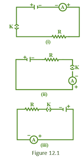
(a) maximum in (i)
(b) maximum in (ii)
(c) maximum in (iii)
(d) the same in all the cases
Ans: (d) the same in all the cases
Explanation: In none of the circuits, the conditions change. As a result, the current in all circuits would be the same.
2. In the following circuits (Figure 12.2), heat produced in the resistor or combination of resistors connected to a 12 V battery will be
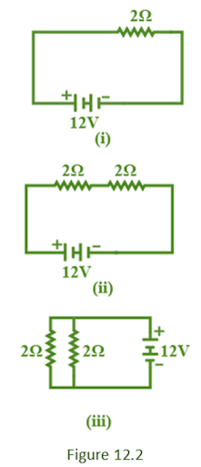
(a) same in all the cases
(b) minimum in case (i)
(c) maximum in case (ii)
(d) maximum in case (iii)
Ans: (c) maximum in case (ii)
Explanation: Two resistors are connected in series in this scenario. As a result, their total will match their arithmetic total. Because the individual resistances are connected in parallel, the overall resistance in figure (iii) will be less than the individual resistances. Option(c) is correct since a larger resistance produces more heat.
3. Electrical resistivity of a given metallic wire depends upon
(a) its length
(b) its thickness
(c) its shape
(d) nature of the material
Ans: (d) nature of the material
Explanation: The resistivity of a metallic wire is determined by the nature of the wire's substance rather than its geometry. As a result, option (D) is correct.
4. A current of 1 A is drawn by a filament of an electric bulb. Number of electrons passing through a cross-section of the filament in 16 seconds would be roughly
(a) \[10^{20}\]
(b) \[10^{16}\]
(c) \[10^{18}\]
(d) \[10^{23}\]
Ans: (a) \[10^{20}\]
Explanation: We know:
\[ {\text{I}} = \frac{{\text{Q}}}{{\text{t}}}\;or\;1{\text{A}} = \frac{{\text{Q}}}{{16\;{\text{s}}}}or\;{\text{Q}} = \;16{\text{C}} \]
Charge contained in 1 electron \[ = \;1.6 \times {10^{ - 19}}\;{\text{C}} \]
So, 16 C charge is contained in the following number of electrons;
\[ \frac{1}{{1.6 \times {{10}^{ - 19}}}} \times 16 = {10^{20}} \]
5. Identify the circuit (Figure 12.3) in which the electrical components have been properly connected.
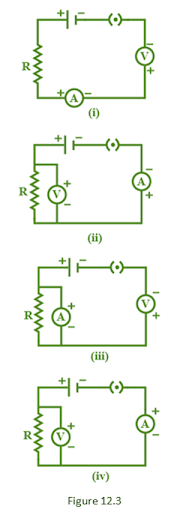
(a) (i)
(b) (ii)
(c) (iii)
(d) (iv)
Ans: (b) (ii)
Explanation: The positive terminal of the ammeter is linked to the negative terminal of the cell in circuit (iv). As a result, it is improper. In contrast, all of the terminals in circuit (ii) are properly connected. As a result, option (B) is the proper choice.
6. What is the maximum resistance which can be made using five resistors each of 1/5 Ω?
(a)1/5 Ω
(b)10 Ω
(c)5 Ω
(d)1 Ω
Ans: (d)1 Ω
Explanation: Combining resistances in parallel lowers equivalent resistance while combining resistances in series raises equivalent resistance, as we all know. To acquire the highest possible resistance, connect all five resistors in series.
\[ {{\text{R}}_{\max }}={{\text{R}}_{1}}+{{\text{R}}_{2}}+{{\text{R}}_{3}}+{{\text{R}}_{4}}+{{\text{R}}_{5}}{{\text{R}}_{\max }}=\text{R}+\text{R}+\text{R}+\text{R}+\text{R}=5\text{R}{{\text{R}}_{\max }}=5~\times \frac{1}{5}=1\text{ }\!\!\Omega\!\!\text{ } \]
7. What is the minimum resistance which can be made using five resistors each of 1/5 Ω?
(a)1/5 Ω
(b)1/25 Ω
(c)1/10 Ω
(d)25 Ω
Ans: (b)1/25 Ω
Explanation: When resistors are connected in parallel then we get the minimum resistance out of the combination. When given resistors are connected in parallel, the resistance of the combination can be calculated as follows:
\[ \frac{1}{\text{R}}=5+5+5+5+5=25\text{ }\!\!\Omega\!\!\text{ }or~\text{R}~=~\frac{1}{25}~\text{Q} \]
8. The proper representation of series combination of cells (Figure12.4) obtaining maximum potential is
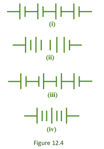
(a) (i)
(b) (ii)
(c) (iii)
(d) (iv)
Ans: (a) (i)
Explanation: The positive terminal of the following cell is near to the negative terminal of the preceding cell in this combination.
9. Which of the following represents voltage?
(a) \[ \frac{~Work~done~}{~Current~\times ~Time~} \]
(b) \[ ~Work~done~\times ~Charge~ \]
(c) \[ \frac{{Work\;done\; \times \;Time}}{{Current}} \]
(d) \[ ~Workdone~\times ~Charge~\times ~Time~ \]
Ans: (a) \[ \frac{~Work~done~}{~Current~\times ~Time~} \]
10. A cylindrical conductor of length l and uniform area of cross-section A has resistance R. Another conductor of length 2l and resistance R of the same material has area of cross-section
(a) A/2
(b) 3A/2
(c) 2A
(d) 3A
Ans: (c) 2A
Explanation: Both the conductors are of same material hence their resistivity is same
\[ \text{ }\!\!\rho\!\!\text{ =}\frac{RA}{\text{l}}For~double~the~length;~or,~\text{p}=\frac{RA'}{2\text{l}}~or,~\frac{RA'}{2\text{l}}=\frac{RA}{\text{l}}~or,~\text{A}'=2\text{A} \]
11. A student carries out an experiment and plots the V-I graph of three samples of nichrome wire with resistances \[R_{1}, R_{2}, and R_{3}\] respectively (Figure.12.5). Which of the following is true?
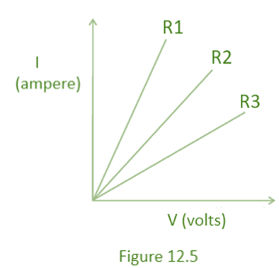
(a) \[R_{1} = R_{2} = R_{3}\]
(b) \[R_{1} > R_{2} > R_{3}\]
(c) \[R_{3} > R_{2} > R_{1}\]
(d) \[R_{2} > R > R_{1}\]
Ans: (c) \[R_{3} > R_{2} > R_{1}\]
Explanation: Resistance is inversely proportional to current. As a result, increased resistance allows less current to pass, as demonstrated by resistance \[R_{3}\].
12. If the current I through a resistor is increased by 100% (assume that temperature remains unchanged), the increase in power dissipated will be
(a) 100 %
(b) 200 %
(c) 300 %
(d) 400 %
Ans: (c) 300 %
Explanation: The heat produced by a resistor is proportional to the square of the current. As a result, when current doubles, heat dissipation multiplies by 22=4. This indicates there will be a 300% increase.
13. The resistivity does not change if
(a) the material is changed
(b) the temperature is changed
(c) the shape of the resistor is changed
(d) both material and temperature are changed
Ans: (c) the shape of the resistor is changed
Explanation: Resistivity of a material is determined by the nature of the wire's material rather than its geometry. As a result, changing the shape of the resistor has no effect on the material's resistance. The correct answer is option C.
14. In an electrical circuit three incandescent bulbs A, B and C of rating40 W, 60 W and 100 W respectively are connected in parallel to an electric source. Which of the following is likely to happen regarding their brightness?
(a) Brightness of all the bulbs will be the same
(b) Brightness of bulb A will be the maximum
(c) Brightness of bulb B will be more than that of A
(d) Brightness of bulb C will be less than that of B
Ans: (c) Brightness of bulb B will be more than that of A
Explanation: Because the bulbs are connected in parallel, the combined resistance is less than the arithmetic total of all the bulbs' resistance. As a result, there will be no detrimental impact on current flow. As a result, bulbs would glow in a wattage-dependent manner.
15. In an electrical circuit, two resistors of 2 Ω and 4 Ω respectively are connected in series to a 6 V battery. The heat dissipated by the 4 Ω resistor in 5 s will be
(a) 5 J
(b) 10 J
(c) 20 J
(d) 30 J
Ans: (c) 20 J
Explanation: Total resistance of combination= \[ 2\text{ }\!\!\Omega\!\!\text{ }+4\text{ }\!\!\Omega\!\!\text{ }=6\text{ }\!\!\Omega\!\!\text{ } \]
Current through the circuit can be calculated as follows: \[ \text{I}=\frac{\text{V}}{\text{R}}=\frac{6\text{V}}{6\text{ }\!\!\Omega\!\!\text{ }}=1\text{A} \]
Heat dissipation by 4Ω can be calculated as follows:
\[ \text{H}={{\text{I}}^{2}}Rt={{\left( 1\text{A} \right)}^{2}}\times 4\text{ }\!\!\Omega\!\!\text{ }~\text{ }\!\!~\!\!\text{ }\times 5\text{s}=~20\text{J} \]
16. An electric kettle consumes 1 kW of electric power when operated at 220 V. A fuse wire of what rating must be used for it?
(a) 1 A
(b) 2 A
(c) 4 A
(d) 5 A
Ans: (c) 4 A
Explanation: Power= \[ 1kW=1000\text{W} \]
Current flowing through the kettle can be calculated as follows: \[ \text{P}=\text{V}\times \text{I} \]
or \[ 1000~\text{W}=220\text{V}\times \text{I} \]
or \[ \text{I}=\frac{1000\text{W}}{220\text{V}}=4.54\text{V} \]
So, required rating off use wire = 5A
17. Two resistors of resistance 2 Ω and 4 Ω when connected to a battery will have
(a) same current flowing through them when connected in parallel
(b) same current flowing through them when connected in series
(c) same potential difference across them when connected in series
(d) different potential difference across them when connected in parallel
Ans: (b) same current flowing through them when connected in series
Explanation: Because each resistor receives the same current in a series combination, current does not change. To put it another way, the current is not separated into branches.
18. Unit of electric power may also be expressed as
(a) volt ampere
(b) kilowatt hour
(c) watt second
(d) joule second
Ans: (b) kilowatt hour
Short Answer Questions
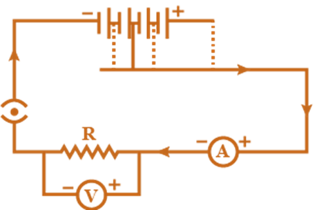
19. A child has drawn the electric circuit to study Ohm’s law as shown in Figure 12.6. His teacher told that the circuit diagram needs correction. Study the circuit diagram and redraw it after making all corrections.
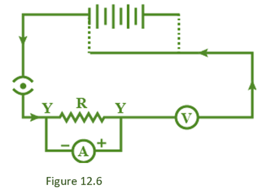
Ans: Correct diagram is as follows:
20. Three 2 Ω resistors, A, B, and C, are connected as shown in Figure 12.7. Each of them dissipates energy and can with stand a maximum power of 18W without melting. Find the maximum current that can flow through the three resistors?
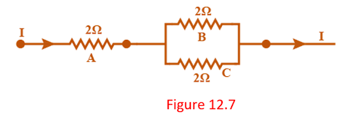
Ans: \[ \text{P}={{\text{I}}^{2}}\text{R}\text{ }\!\!~\!\!\text{ or}\text{, }\!\!~\!\!\text{ }18\text{W}={{\text{I}}^{2}}~\times ~2\text{ }\!\!\Omega\!\!\text{ }\text{ }\!\!~\!\!\text{ or}\text{, }\!\!~\!\!\text{ }{{\text{I}}^{2}}=\frac{18\text{W}}{2\text{ }\!\!\Omega\!\!\text{ }}=9\text{ }\!\!~\!\!\text{ or}\text{, }\!\!~\!\!\text{ I}=3\text{A} \]
This is the maximum current that can flow through the given resistors.
21. Should the resistance of an ammeter be low or high? Give a reason.
Ans: Because an ammeter is connected in series in a circuit, its resistance should be low. If the resistance is large, no current will pass through the circuit.
22. Draw a circuit diagram of an electric circuit containing a cell, a key, an ammeter, a resistor of 2 Ω in series with a combination of two resistors (4 Ω each) in parallel and a voltmeter across the parallel combination. Will the potential difference across the 2 Ω resistor be the same as that across the parallel combination of4Ω resistors? Give reason.
Ans:
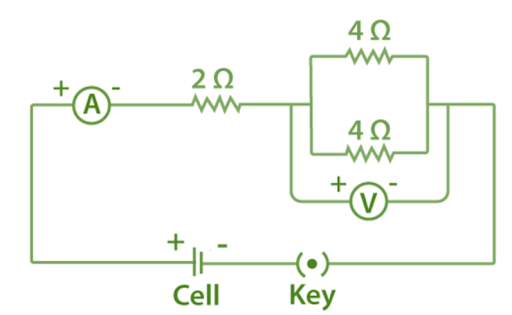
\[ Total~resistance~for~parallel~combination~of~4\text{ }\!\!\Omega\!\!\text{ }~resistors~can~be~calculated~as~follows\frac{1}{R}=\frac{1}{4}+\frac{1}{4}=\frac{1}{2}or,~\text{R}~=~2~\text{ }\!\!\Omega\!\!\text{ } \]
Thus, the resistance of a parallel combination equals the resistance of a series of resistors. As a result, the potential difference across a 2-ohm resistance will be the same as the potential difference across the other two resistors linked in parallel.
23. How does the use of a fuse wire protect electrical appliances?
Ans: The fuse in electrical appliances is used to protect the equipment from excessive current flow. When there is a large current flow, the fuse melts and the current in the appliance stops flowing.
24. What is electrical resistivity? In a series electrical circuit comprising a resistor made up of a metallic wire, the ammeter reads 5 A. The reading of the ammeter decreases to half when the length of the wire is doubled. Why?
Ans: The property of a conductor that causes it to resist the flow of electric current is known as resistivity. The resistivity of a given substance is one-of-a-kind.
The resistance of a conductor is proportional to its length.
The resistance has an inverse relationship with current.
As a result, when the wire's length is twice, its resistance is also doubled. When the resistance is doubled, the current is cut in half.
This explains why when the wire length is doubled, the ammeter value drops to half.
25. What is the commercial unit of electrical energy? Represent it in terms of joules.
Ans: The kilowatt hour is a commercial unit of electrical energy.
\[ 1kWh=11000Wh \]
\[ 1000Wh=\left( 1000\text{ }\!\!~\!\!\text{ Joule/second }\!\!~\!\!\text{ } \right)\times \text{ }\!\!~\!\!\text{ hour }\!\!~\!\!\text{ } \]
\[ 1000\times \frac{\text{J}}{\text{S}}\times 60\times 60\text{s} \]
\[ = 3600\; \times \;1000\;J \]
\[ =3.6\times {{10}^{6}}\text{J} \]
26. A current of 1 ampere flows in a series circuit containing an electric lamp and a conductor of 5 Ω when connected to a 10 V battery. Calculate the resistance of the electric lamp. Now if a resistance of 10 Ω is connected in parallel with this series combination, what change (if any) in current flowing through5 Ω conductor and potential difference across the lamp will take place? Give reason.
Ans: Total resistance of a circuit can be calculated as follows:
\[ \text{R}=\frac{\text{V}}{\text{I}}=\frac{10\text{V}}{1\text{A}}=10\text{ }\!\!\Omega\!\!\text{ } \]
Since lamp and conductor are in series so resistance of lamp
\[ =10\text{ }\!\!\Omega\!\!\text{ }-5\text{ }\!\!\Omega\!\!\text{ }=5\text{ }\!\!\Omega\!\!\text{ } \]
The new resistance in parallel to earlier combination has same value, i.e. 10 Ω as the resistance of series combination. This means that the amount of current would be equally divided into two branches. Hence, 0.5A current will flow through 5 Ω conductor. Now, resistance remains the same but current has become half. Using Ohm formula, potential difference across the lamp can be calculated as follows:
\[ \text{ }\!\!~\!\!\text{ V}=IR=0.5\text{A}\times 5\text{ }\!\!\Omega\!\!\text{ }=2.5\text{V} \]
27. Why is parallel arrangement used in domestic wiring?
Ans: The total resistance of the circuit is smaller than the arithmetic sum of the resistors in the wiring in a parallel design. This reduces the amount of strain on the wiring. Each appliance in a parallel layout can have its own switch. A flaw in one section will not affect the rest of the system. Parallel wiring is great for household wiring because of these benefits.
28. \[B_{1}, B_{2}, and B_{3}\] are three identical bulbs connected as shown in Figure 12.8. When all the three bulbs glow, a current of 3A is recorded by the ammeter A.
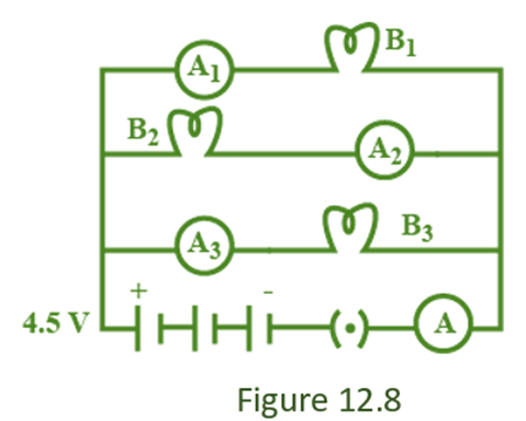
(i) What happens to the glow of the other two bulbs when the bulb \[B_{1} \] gets fused?
Ans: The potential difference in a parallel circuit is not split. As a result, when bulb \[B_{1} \] is fused, the glow of the other bulbs will not be altered.
(ii) What happens to the reading of \[A_{1}, A_{2}, A_{3}, and A\] when the bulb \[B_{2}\] gets fused?
Ans: The reading on ammeter A is 3A. This indicates that each of the \[A_{1}, A_{2}, and A_{3} \] has a 1A reading. When bulb \[B_{2}\] has blown, there is no current flowing through it. As a result, the remaining two bulbs receive an equal share of the current. As a result, ammeters \[A_{1}, and A_{2}\] will each show 3/2 = 1.5A current. The current on the ammeter \[ A_{3} \] will be zero.
(iii) How much power is dissipated in the circuit when all the three bulbs glow together?
Ans: For finding power, we need to first calculate the resistance in the circuit.
\[ {\text{R}} = \frac{{\text{V}}}{{\text{I}}} = \frac{{4.5\;{\text{V}}}}{{3\;{\text{A}}}} = 1.5{\text{ }}\Omega {\text{ }} \]
\[ \text{ }\!\!~\!\!\text{ Now}\text{, }\!\!~\!\!\text{ P}={{\text{I}}^{2}}\text{R}={{(3\text{A})}^{2}}\times 1.5\text{ }\!\!\Omega\!\!\text{ }=13.5~\text{W} \]
Long Answer Questions
29. Three incandescent bulbs of 100 W each are connected in series in an electric circuit. In another circuit, another set of three bulbs of the same wattage are connected in parallel to the same source.
(a) Will the bulb in the two circuits glow with the same brightness? Justify your answer.
Ans: Because the voltage is divided in a series combination, the bulbs will glow with less brilliance. Because voltage is not divided in a parallel configuration, bulbs in a parallel configuration will glow brighter.
(b) Now let one bulb in both the circuits get fused. Will the rest of the bulbs continue to glow in each circuit? Give reason.
Ans: If a single component fails in a series combination, the circuit will be broken. As a result, if one of the bulbs becomes fused, the other bulb will continue to glow.
30. State Ohm’s law? How can it be verified experimentally? Does it hold good under all conditions? Comment.
Ans: Ohm’s law: At constant temperature, the potential difference across a conductor is proportional to the electric current going through it, according to Ohm's Law. According to Ohm's law, if V is the potential difference and I is the electric current,
\[ {\text{V}} \propto 1{\text{ }}\;{\text{ or}}{\text{, }}\;{\text{ }}\frac{{\text{V}}}{{\text{I}}} = {\text{R}} \]
Where R is the constant of proportionality and it is called resistance.
Verifying Ohm’s law:
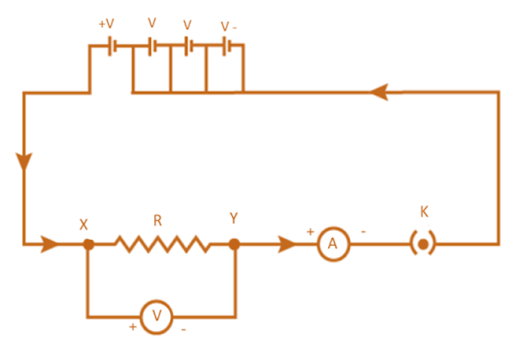
Electric circuit for studying Ohm’s law
(i) As illustrated in the diagram, connect the wires as described.
(ii) To boost the current in the circuit, turn up the rheostat.
(iii) Use the ammeter to determine the current in the circuit, as well as the voltmeter to determine the potential difference.
(iv) Check the brightness of the linked bulb for an increase in current. Calculate the bulb's resistance using everything you've learned so far.
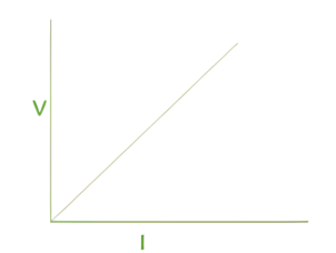
When current in the circuit (I) is shown along the x axis and potential (V) is plotted along the y axis, the graph of Ohm's law is a straight line. The resulting graph is depicted in the diagram below.
Ohm's Law must meet certain conditions in order to be valid.
Under all circumstances, Ohm's law does not apply.
(i) For non-ohmic materials like electrolyte, Ohm's law does not apply.
(ii) Ohm's law does not hold true in fluctuating temperature circumstances.
31. What is electrical resistivity of a material? What is its unit? Describe an experiment to study the factors on which the resistance of conducting wire depends.
Ans: The property of a conductor that causes it to resist the flow of electric current is known as resistivity. The resistivity of a given substance is one-of-a-kind.
The SI unit of resistivity is Ω m (Ohm metre).
Experiment to study the factors on which resistance of conducting wire depends:
(i) Take an ammeter, an electric cell, a plug key, nichrome wire, and other wires.
(ii )Assemble the circuit as shown in the diagram.
(iii) Begin by using nichrome wire in your experiment. Connect it to the circuit and read the ammeter.
(iv) Take an ammeter reading while changing the length of the nichrome wire.
(v) Take ammeter readings while the thickness of the nichrome wire is changed.
(vi) Use copper wire for the experiment after you've completed the instructions above. Take an ammeter reading by connecting a copper wire to the circuit
(vii) Take an ammeter reading while changing the length of copper wire.
(viii )Change the copper wire thickness and take an ammeter measurement.
(ix) Rep the procedures above with wires of various materials.
Observations:
(i) It can be shown that resistance is affected by the conductor's substance.
(ii) Resistance is proportional to conductor length.
(iii) Resistance is proportional to the cross-sectional area.
32. How will you infer with the help of an experiment that the same current flows through every part of the circuit containing three resistances in series connected to a battery?
Ans:
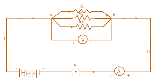
Take a battery, an ammeter, a voltmeter, and some cables, as well as three resistors \[R_{1}, R_{2}, and R_{3}\]. As illustrated in the diagram, complete the circuit.
When all three resistors are connected in parallel, measure the potential difference.
Remove one of the resistors and compare the potential differences of the remaining two parallel resistors.
Remove the second resistor and calculate the potential difference between the remaining resistor and the second resistor.
In all of these situations, the voltmeter displays the same reading. This demonstrates that the same potential difference persists across three resistors wired in parallel.
33. How will you conclude that the same potential difference (voltage)exists across three resistors connected in a parallel arrangement to a battery?
Ans: (i) Connect three resistors \[R_{1}, R_{2}, and R_{3}\] in parallel to form the circuits illustrated in the figure.
(ii) Using a voltmeter, measure the potential difference between three resistors connected in parallel.
(iii) Now, remove resistor R1 and measure the potential difference of the remaining resistor combination.
(iv) Next, remove resistor R2 and measure the potential difference of the remaining resistance.
Observation: The voltmeter readings were identical in each case. This demonstrates that a potential difference occurs between three resistors linked in parallel.
34. What is Joule’s heating effect? How can it be demonstrated experimentally? List its four applications in daily life.
Ans: According to Joule's Law of Heating, the heat produced in a resistor is
(a) directly proportional to the square of current for a given resistor.
(b) Directly proportional to resistance for a given current, and
(c) Directly proportional to the time the current passes through the resistor.
This can be expressed by following equation:
\[ {\text{H}} = {{\text{I}}^2}Rt \]
Here; I is an electric current, R is resistance, t is time and H is a heating effect.
Experiment to Demonstrate Joule's Law of Heating:
(i) In this experiment, we will show the effect of current on heating.
(ii)Take a water heating immersion rod and connect it to a socket which is connected to the regulator. It is important to recall that a regulator controls the amount of current flowing through a device.
(iii)Keep the pointer of the regulator on a minimum and count the time taken by the immersion rod to heat a certain amount of water.
(iv)Increase the pointer of the regulator to the next level. Count the time taken by immersion rod to heat the same amount of water.
(v)Repeat the above step for higher levels on the regulator to count the time.
Observation: It is seen that with an increased amount of electric current, less time is required to heat the same amount of water. This shows Joule's Law of Heating.
Application: Electric toaster, oven, electric kettle and electric heater etc. work on the basis of heating effect of current.
35. Find out the following in the electric circuit given in Figure 12.9
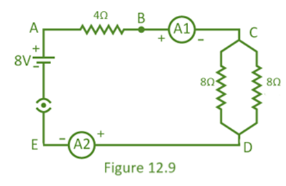
(a) Effective resistance of two 8 Ω resistors in the combination
Ans: These resistors are in parallel, so effective resistance can be calculated as follows:
\[\frac{1}{{\text{R}}} = \frac{1}{{8\Omega }} + \frac{1}{{8\Omega }} = \frac{{1 + 1}}{8}\Omega = \frac{2}{8}\Omega = \frac{1}{4}\Omega {\text{ or R}} = 4\Omega \]
(b) Current flowing through 4 Ω resistor
Ans: For this, we first need to find effective resistance in the circuit,
\[ = 4{\text{ }}\Omega {\text{ }} + 4{\text{ }}\Omega {\text{ }} = 8{\text{ }}\Omega {\text{ }} \]
\[ \frac{{\text{V}}}{1} = {\text{R }}\;{\text{ or }}\;{\text{ I}} = \frac{{\text{V}}}{{\text{R}}} = \frac{{8{\text{V}}}}{{8{\text{ }}\Omega {\text{ }}}} = 1{\text{A}} \]
(c) Potential difference across 4 Ω resistance
Ans: Potential difference is getting divided into two resistance of 4 Ω each. Hence, the potential difference across
\[ 4~\text{ }\!\!\Omega\!\!\text{ }~=~\frac{8\text{V}}{2}=~4~\text{V} \]
(d) Power dissipated in 4 Ω resistor
Ans: \[ \text{P}={{\text{I}}^{2}}\text{R}={{(1\text{A})}^{2}}\times 4\text{ }\!\!\Omega\!\!\text{ }=4\text{W} \]
(e)Difference in ammeter readings, if any.
Ans: Because the resistors are connected in series, the ammeter reading will be the same.
Vedantu’s Class 10 Science NCERT Exemplar for Chapter 12- Electricity - Free PDF Download
Vedantu’s Class 10 Science NCERT Exemplar Solutions for Class 10 Science Chapter 12 Electricity is a study material that is essential for Class 10 students to understand the concepts in the "Electricity" Chapter. It is important for the students to get connected with this chapter that will help them to score good marks in their CBSE Class 10 science examination. This solution set helps in a proper way with answers to the questions provided in NCERT Class 10 science textbook.
How is Vedantu Helpful?
Vedantu is offering a free NCERT Exemplar for Class 10 Science Chapter 12 to help students to understand all the concepts in detail. These exemplars will help students to get the correct answers to all the questions given on the end page of the chapter. These NCERT Exemplars are prepared by professional science teachers at Vedantu and these can also be used as an effective learning tool.
NCERT exemplar Solutions for Class 10 Science PDF includes NCERT textbook solutions. NCERT Solutions for CBSE Class 10 Science have a total of 16 chapters including Chapter 12 “Electricity”. Vedantu’s Class 10 Science NCERT Exemplar Solutions for Class 10 Science Chapter 12 Electricity with the latest modifications and as per the latest CBSE syllabus are only available on Vedantu.


FAQs on NCERT Exemplar for Class 10 Science Chapter 12 - Electricity (Book Solutions)
Vedantu’s Chapter 8 of NCERT Exemplar Solutions for Class 10 Science covers some topics. They are listed below:
Introduction to electricity
Current
The potential difference – Definition of volt and voltmeter
Ohm’s law – Ohm and resistance
Factors on which the resistance of the conductor depends – Resistivity
Resistors in series – Total/resultant/ overall and voltage across each resistor
Resistors in parallel
The advantage of parallel combination over the series combination
Heating effect of an electric circuit – Joule’s law of the heating effect of electric current, electric fuse, electric power.
Experiment to test Joule's law of heating:
- The first step is to take a water heating immersion rod and connect it to a socket that is connected to the regulator. It Is important to remember that a regulator controls the current flowing through that device.
- Put the regulator pointer at zero and count the time taken by the immersion rod to heat a certain amount of water. and note down the water quantity.
- Slightly start Increasing the pointer of the regulator to the next level from zero.
- Again Count the time taken by the immersion rod to heat the same amount of water.
- Repeat the above step for higher levels on the regulator to count the time till it is proven.
3. How is Vedantu's NCERT Exemplar Solutions for Class 10 Science Chapter 12 the best study material for the students?