


NCERT Exemplar for Class 12 Physics - Wave Optics - Free PDF Download
MULTIPLE CHOICE QUESTIONS-I
10.1 Consider a light beam incident from air to a glass slab at Brewster’s angle as shown in Fig. 10.1. A polaroid is placed in the path of the emergent ray at point P and rotated about an axis passing through the centre and perpendicular to the plane of the polaroid.
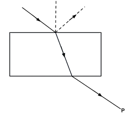
(a) For a particular orientation there shall be darkness as observed through the polaoid.
(b) The intensity of light as seen through the Polaroid shall be independent of the rotation.
(c) The intensity of light as seen through the Polaroid shall go through a minimum but not zero for two orientations of the polaroid.
(d) The intensity of light as seen through the polaroid shall go through a minimum for four orientations of the polaroid.
Ans: (c): When ray ABCD of light passes through prism in such a way that angle between reflected ray BE and refracted ray BC is \[{90^ \circ }\] then only reflected ray is plane polarized. So Polaroid rotated in the way of CD the intensity will never be zero but varies in one complete rotation so, it verifies answer (c).
10.2 Consider sunlight incident on a slit of width \[{10^4}A\] . The image seen through the slit shall
(a) Be a fine sharp slit white in colour at the center.
(b) A bright slit white at the center diffusing to zero intensities at the edges.
(c) A bright slit white at the center diffusing to regions of different colours.
(d) Only be a diffused slit white in colour.
Ans: (a): Width of slit \[{\mathbf{1}}{{\mathbf{0}}^4}\mathop A\limits^ \circ \; = {\mathbf{10}},{\mathbf{000}}\mathop A\limits^ \circ \] .
Wavelength of visible light varies from \[4000\] to $8000\mathop A\limits^ \circ $ . As the width of slit \[10000\mathop A\limits^ \circ \] is comparable to that of wavelength of visible light i.e. $8000\mathop A\limits^ \circ $ . Hence the diffraction occurs with maxima at the centre. So at the centre all colours appear i.e. white colour at the centre appear.
10.3 Consider a ray of light incident from air onto a slab of glass (refractive index \[{\mathbf{n}}\] ) of width \[{\mathbf{d}}\] , at an angle \[{\mathbf{\theta }}\] . The phase difference between the ray reflected by the top surface of the glass and the bottom surface is
(a) $\dfrac{{2\pi \mu d}}{\lambda }{\left[ {1 - \dfrac{1}{{{n^2}}}{{\sin }^2}\theta } \right]^{\dfrac{1}{2}}} + \pi $
(b) $\dfrac{{4\pi d}}{\lambda }{\left[ {1 - \dfrac{1}{{{n^2}}}{{\sin }^2}\theta } \right]^{\dfrac{1}{2}}}$
(c) $\dfrac{{4\pi d}}{\lambda }{\left[ {1 - \dfrac{1}{{{n^2}}}{{\sin }^2}\theta } \right]^{\dfrac{1}{2}}} + \dfrac{\pi }{2}$
(d) \[\dfrac{{4\pi d}}{\lambda }{\left[ {1 - \dfrac{1}{{{n^2}}}{{\sin }^2}\theta } \right]^{\dfrac{1}{2}}} + 2\pi \]
Ans: (a): Consider a ray of light ABCD through prism, and reflected rays BE and CF from incidence points B and C as shown in figure.
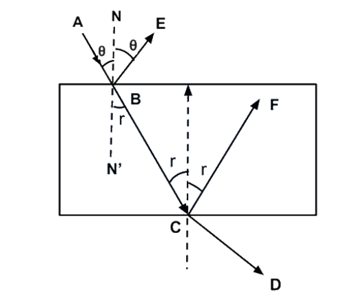
The time difference between two reflected ray BE and CF is equal to the time taken by ray to travel from B to C.
$\therefore $ Time difference \[dt\] between two reflected rays BE and CF are
$dt = \dfrac{{BC}}{{{v_g}}}\,.....\left( I \right)$
$\because \mu = \dfrac{{{v_a}}}{{{v_g}}}$
${v_a} = c$
$\therefore {v_g} = \dfrac{c}{\mu }\,...\left( {II} \right)$
$\cos r = \dfrac{d}{{BC}}$
$BC = \dfrac{d}{{\cos r}}\,....\left( {III} \right)$
$dt = \dfrac{{\dfrac{d}{{\cos r}}}}{{\dfrac{c}{\mu }}}\,...\left( {IV} \right)$
$\mu = \dfrac{{\sin \theta }}{{\sin r}}$
$or,\,\sin r = \dfrac{{\sin \theta }}{\mu }$
$\cos r = \sqrt {1 - {{\sin }^2}r} = \sqrt {1 - \dfrac{{{{\sin }^2}\theta }}{{{\mu ^2}}}} $
Substitute (I) and (II) in (III)
$t = \dfrac{{\dfrac{d}{{\cos r}}}}{{\dfrac{c}{\mu }}}\,...\left( {IV} \right)$
$\mu = \dfrac{{\sin \theta }}{{\sin r}}$
$or,\,\sin r = \dfrac{{\sin \theta }}{\mu }$
$\cos r = \sqrt {1 - {{\sin }^2}r} = \sqrt {1 - \dfrac{{{{\sin }^2}\theta }}{{{\mu ^2}}}} $
From IV, $dt = \dfrac{{\mu d}}{{c\sqrt {1 - \dfrac{{{{\sin }^2}\theta }}{{{\mu ^2}}}} }} = \dfrac{{\mu d}}{c} = {\left[ {1 - \dfrac{{{{\sin }^2}\theta }}{{{\mu ^2}}}} \right]^{ - \dfrac{1}{2}}}$
Phase difference,
$d{\phi ^,} = \dfrac{{2\pi }}{T}dt = \dfrac{{2\pi \mu d}}{{Tc}}{\left[ {1 - \dfrac{{{{\sin }^2}\theta }}{{{\mu ^2}}}} \right]^{ - \dfrac{1}{2}}}$
$d{\phi ^,} = \dfrac{{2\pi \mu d}}{{\dfrac{1}{v}v\lambda }}{\left[ {1 - \dfrac{1}{{{\mu ^2}}}{{\sin }^2}\theta } \right]^{ - \dfrac{1}{2}}}$
$d{\phi ^,} = \dfrac{{2\pi \mu d}}{\lambda }{\left[ {1 - \dfrac{1}{{{\mu ^2}}}{{\sin }^2}\theta } \right]^{ - \dfrac{1}{2}}}$
The phase difference between ray AB and BC after refraction is $\pi $
$\therefore $ Net phase difference $ = d{\phi ^,} + \pi $
$ = d\phi = \dfrac{{2\pi \mu d}}{\lambda }{\left[ {1 - \dfrac{{{{\sin }^2}\theta }}{{{\mu ^2}}}} \right]^{ - \dfrac{1}{2}}} + \pi $ (It is very near to option (a))
10.4 In a Young’s double slit experiment, the source is white light. One of the holes is covered by a red filter and another by a blue filter. In this case
(a) There shall be alternate interference patterns of red and blue.
(b) There shall be an interference pattern for red distinct from that for blue.
(c) There shall be no interference fringes.
(d) There shall be an interference pattern for red mixing with one for blue.
Ans: (c): For sustained interference, the source must be coherent and should emit the light of same frequency. In this problem one hole is covered with red and other with blue, which has different frequency, so no interference takes place.
10.5 Figure 10.2 shows a standard two slit arrangement with slits \[{S_1},{\text{ }}{S_2}\] . \[{P_1},{\text{ }}{P_2}\] are the two minima points on either side of P (Fig. 10.2). At \[{P_2}\] on the screen, there is a hole and behind \[{P_2}\] is a second screen, 2- slit arrangement with slits \[{S_3}\] and and a second screen behind them.
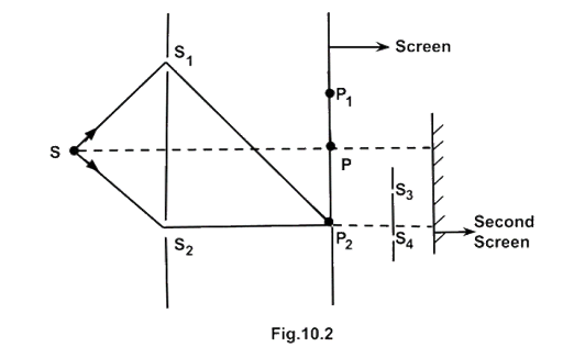
(a) There would be no interference pattern on the second screen but it would be lighted.
(b) The second screen would be totally dark.
(c) There would be a single bright point on the second screen.
(d) There would be a regular two slit pattern on the second screen.
Ans: (d): At \[{P_2}\] is minima due to two wavefronts in opposite phase coming from, two slits \[{S_1}\] and \[{S_2}\] , but there is wavefronts from \[{S_1},{\text{ }}{S_2}\] so \[{P_2}\] will act as a source of secondary wavelets. Wavefront starting from \[{P_2}\] reaches at \[{S_3}\] and \[{S_4}\] slits which will again acts as two monochromatic or coherent sources and will form pattern on second screen.
MULTIPLE CHOICE QUESTIONS-II
MORE THAN ONE OPTION
10.6 Two source \[{{\mathbf{S}}_1}\] and \[{{\mathbf{S}}_{\mathbf{2}}}\] of intensity \[{{\mathbf{I}}_1}\] and \[{{\mathbf{I}}_2}\] are placed in front of a screen [Fig. 10.3 (a)]. The pattern of intensity distribution seen in the central portion is given by Fig. 10.3 (b). In this case which of the following statements are true
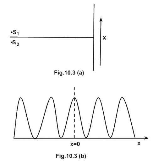
(a) \[{{\mathbf{S}}_1}\] and \[{{\mathbf{S}}_{\mathbf{2}}}\] have the same intensities.
(b) \[{{\mathbf{S}}_1}\] and \[{{\mathbf{S}}_{\mathbf{2}}}\] have a constant phase difference.
(c) \[{{\mathbf{S}}_1}\] and \[{{\mathbf{S}}_{\mathbf{2}}}\] have the same phase.
(d) \[{{\mathbf{S}}_1}\] and \[{{\mathbf{S}}_{\mathbf{2}}}\] have the same wavelength.
Ans: (a), (b) and (c): (i) As the intensity at dark fringe is zero so intensities of \[{S_1}\] and \[{S_2}\] are equal.
(ii) As the graph of maxima and minima is symmetric. So the waves from \[{S_1}\] and \[{S_2}\]are at same phase difference or zero phase difference.
10.7 Consider sunlight incident on a pinhole of width \[{10^3}\mathop A\limits^ \circ \] . The image of the pinhole seen on a screen shall be
(a) A sharp white ring.
(b) Different from a geometrical image.
(c) A diffused central spot, white in colour.
(d) Diffused colored region around a sharp central white spot.
Ans: (b) and (d): The width of pinhole \[{10^3}\mathop A\limits^ \circ = 1000\mathop A\limits^ \circ \] and wavelength of visible light is\[4000\mathop A\limits^ \circ \] to \[8000\mathop A\limits^ \circ \] i.e., size of slit less than (or comparable) with the wavelength of light. So light from pinhole will diffract from the hole. Due to the diffraction pattern of fringes, the shape are quite different from hole.
10.8 Consider the diffraction pattern for a small pinhole. As the size of the hole is increased
(a) The size decreases.
(b) The intensity increases.
(c) The size increases.
(d) The intensity decreases.
Ans: (a) and (b): We know that width \[\left( {{B_0}} \right)\] of central maxima \[{B_0} = \dfrac{{D\lambda }}{d}\] and width of nth secondary maxima \[ = \dfrac{\lambda }{d}\] here distance \[\left( D \right)\] between slit and screen, wavelength \[\lambda \]of source does not change. So on increasing width of hole of pinhole, ‘d’ increase. Hence the size of central maxima decreases verifies the option (a). As the energy passing through hole increased on increasing the size of hole. So the intensity of pattern will increase. Hence verifies the option (b).
10.9 For light diverging from a point source
(a) The wavefront is spherical.
(b) The intensity decreases in proportion to the distance squared.
(c) The wavefront is parabolic.
(d) The intensity at the wavefront does not depend on the distance.
Ans: (a) and (b): light from point source emits in all around the source with same speed so forms a spherical surface of wavefront or spherical wavefront.
As the intensity \[\left( I \right)\] always decreases as the reciprocal of square of distance.
$I = \dfrac{P}{{4\pi {r^2}}}$
\[r = \] radius of spherical wavefront at any time \[\left( {r = vt} \right)\]
VERY SHORT ANSWER TYPE
QUESTIONS
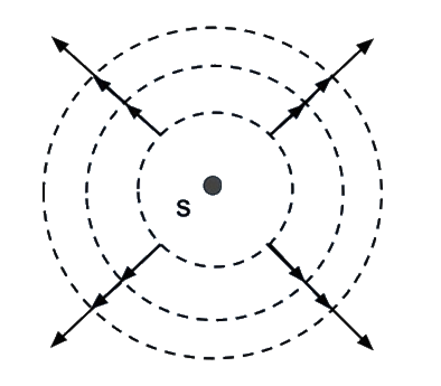
10.10 Is Huygen’s principle valid for longitudinal sound waves?
Ans: Consider a source of sound formed with the compressions and rarefactions forward in all directions with same velocity. So longitudinal waves propagate with spherical symmetry in all directions as the wavefront in light waves. So Huygen’s principle is valid for longitudinal sound waves also.
On a surface of sphere there will be either compression or rarefaction and that part can also behave like a source of sound but with low intensity. On a surface of sphere there will be either compression or rarefaction and that part can also behave like a source of sound but with low intensity.
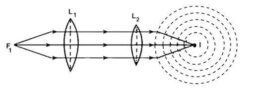
10.11 Consider a point at the focal point of a convergent lens. Another convergent lens of short focal length is placed on the other side. What is the nature of the wavefronts emerging from the final image?
Ans: Consider a point on focus of converging lens \[{L_1}\] . The light rays from \[F\] , becomes parallel after refraction through \[{L_1}\] . When these parallel rays falls on converging lens \[{L_2}\] placed co-axial on the other side of \[F\] of \[{L_1}\] . \[{L_2}\] converges the rays at it’s focus at \[I\] . It now behave like a point source of rays and form a spherical wave front.
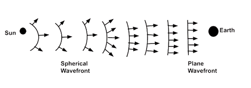
10.12 What is the shape of the wavefront on earth for sunlight?
Ans: As the sun is very-very far from the earth so can be considered at infinity and sun can be considered as a point source which gives spherical wavefront. The size of the earth is very small as compared to distance of sun from earth and size of the sun so the plane wavefront reaches on earth as shown in figure here.
10.13 Why is the diffraction of sound waves more evident in daily experience than that of light wave?
Ans: We know that frequencies of sound waves varies from \[20Hz\] to \[20,000Hz\] , so its corresponding wavelength varies from \[15m\] to \[15mm\] respectively. The size of slit (almost) becomes comparable to wavelength of sound so diffraction of sound wave takes place easily. But the wavelength of visible light varies from \[0.4\] to \[0.7\] micron which is very small. So the size of most of the slits in not comparable with wavelength of visible light, due to this diffraction of light cannot take place.
10.14. The human eye has an approximate angular resolution of \[\phi = {\mathbf{5}}.{\mathbf{8}} \times {\mathbf{1}}{{\mathbf{0}}^{ - {\mathbf{4}}}}{\text{ }}{\mathbf{rad}}\]and a typical photo printer prints a minimum of \[{\mathbf{300dpi}}\] (dots per inch,\[{\mathbf{1}}{\text{ }}{\mathbf{inch}} = {\mathbf{2}}.{\mathbf{54}}{\text{ }}{\mathbf{cm}}\] ). At what minimal distance \[{\mathbf{z}}\] should a printed page be held so that one does not see the individual dots.
Ans: Angular separation \[ = 5.8 \times {10^{ - 4}}{\text{ }}radian\]
The average distance between any two dots $ = \dfrac{{2.54}}{{300}} = 0.85 \times {10^{ - 2}}cm$
At the distance \[z\] cm, angle subtended $ = \dfrac{{arc}}{{rad}} = \dfrac{{0.85 \times {{10}^{ - 2}}}}{z}$
Resolution angle for human $ = 5.8 \times {10^{ - 2}}rad = \dfrac{{0.85 \times {{10}^{ - 2}}}}{z}$
Maximum distance up to which human eye cannot see 2 dots distinctly $ = z = \dfrac{{0.85 \times {{10}^{ - 2}}}}{{5.85 \times {{10}^{ - 2}}}} = 14.5cm$
Which is less than distance of distinct vision. So a normal person cannot see the dots.
10.15. A polaroid (I) is placed in front of a monochromatic source. Another polaroid (II) is placed in front of this polaroid (I) and rotated till no light passes. A third polaroid (III) is now placed in between (I) and (II). In this case, will light emerge from (II). Explain.
Polaroid III is placed between two crossed polaroid’s I and II and no light passes through IInd Polaroid.
Polaroid III is now placed between I, II and now retakes keeping I, II in no rotation. Let angle between Polaroid I and III be \[\theta \] and intensity of plane polarize light after 1st Polaroid is \[{I_0}\] .
Then \[{I_1} = {I_0}\]

${I_3} = {I_0}{\cos ^2}\theta $ is intensity of light after Polaroid III
${I_2} = {I_0}{\cos ^2}\theta .{\cos ^2}\left( {90 - \theta } \right)$
${I_2} = {I_0}{\cos ^2}\theta .{\sin ^2}\theta $
${I_2} = {I_0}{\left( {2\cos \theta \sin \theta } \right)^2} = {I_0}{\left( {\sin 2\theta } \right)^2}$
${I_2} = \dfrac{{{I_0}}}{4}{\sin ^2}2\theta $
$\theta $ is angle between I and III Polaroid.
No light will pass through II Polaroid from above eqn. When
\[{\sin ^2}2\theta = 0\]
\[\sin 2\theta = 0\]
\[\sin 2\theta = \sin 0\]
\[\theta = {0^ \circ }\]
$\therefore $ No light will pass when angle between I and III Polaroid is zero i.e., plane of Polaroid area parallel . In all other cases when III is not parallel to either I or II, right will pass.
SHORT ANSWER TYPE
QUESTIONS
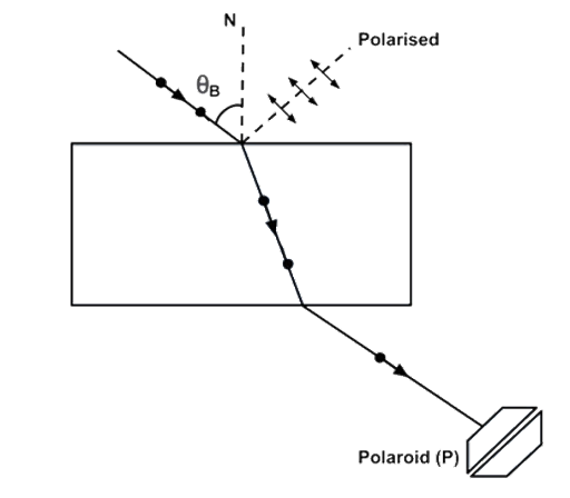
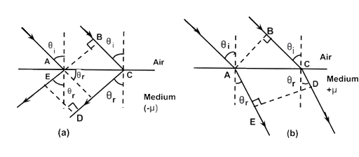
10.16 Can reflection result in plane polarised light if the light is incident on the interface from the side with higher refractive index?
Ans: When a ray of light passes from a medium (air) of refractive index \[{\mu _1}\] to another medium of refractive index ${\mu _2}$ , more than \[{\mu _1}\] with incidence angle is equal to Brewster’s angle \[\left( {{i_B}} \right)\] , then transmitted ray BC will be unpolarised light and the reflected light BD will be plane polarized. Angle DBC between refracted and reflected ray is ${90^ \circ }$ .
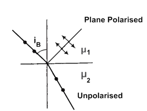
$\angle r + \angle {i_B} + {90^ \circ } = {180^ \circ }$
So, $\angle r + \angle {i_B} + {90^ \circ } = {180^ \circ }$
Or, $\angle r = {90^ \circ } - {i_B}$
By Snell’s law, ${\mu _2} = \dfrac{{\sin {i_B}}}{{\sin r}} = \dfrac{{\sin {i_B}}}{{\cos {i_B}}} = \tan {i_B}$
$\because {\mu _2} > {\mu _1}$
$\therefore \tan {i_{_B}} > 1$
${i_{_B}} > {45^ \circ }$
$\sin {i_c} = \dfrac{1}{{{\mu _2}}}$ when light passes from medium 2 to 1
$\sin {i_c} = \dfrac{{{\mu _1}}}{{{\mu _2}}}\left( {\because {\mu _2} > {\mu _1}} \right)$
Or, ${i_c} < {90^ \circ }$
From I $\tan {i_B} > 1$
From II $1 > \sin {i_c}$
Or, $\tan {i_B} > 1 > \sin {i_c}$
Or, $\left| {\tan {i_B}} \right| > \left| {\sin {i_c}} \right|$
Because $45 < {i_B}$
${i_c} < {90^ \circ }$
So,
${45^ \circ } < {i_B} < {90^ \circ }$
$0 < {i_c} < {90^ \circ }$
So, ${i_B} > {i_c}$
Thus, polarization by reflection takes place.
10.17 For the same objective, find the ratio of the least separation between two points to be distinguished by a microscope for light of\[\]\[5000\mathop A\limits^ \circ \] and electrons accelerated through \[100V\] used as the illuminating substance.
Ans: $\lambda = 5000\mathop A\limits^ \circ = 5000 \times {10^{ - 10}}m$
In microscope, $R.P = \dfrac{1}{d} = \dfrac{{2\sin \beta }}{{1.22\lambda }}$
Limit of resolution by light of \[5000\mathop A\limits^ \circ \]
${d_{\min }} = \dfrac{{1.22\lambda }}{{2\sin \beta }}or,\,{d_{\min }} = \dfrac{{1.22 \times 5000 \times {{10}^{ - 10}}}}{{2\sin \beta }}$
The de Broglie wavelength \[{\lambda _d}\] of illuminated light $ = \dfrac{{1.22}}{{\sqrt V }}nm$
${\lambda _d} = \dfrac{{1.22}}{{\sqrt {100} }}nm = \dfrac{{1.22}}{{10}} \times {10^{ - 10}}m$
The limit of resolution by \[100{\text{ }}V\] light ${d_{\min }} = \dfrac{{1.22{\lambda _d}}}{{2\sin \beta }}$
${d_{\min }} = \dfrac{{1.22 \times 1.22 \times {{10}^{ - 10}}}}{{2\sin \beta }}$
The required ratio$\dfrac{{{d_{\min }}}}{{{d_{\min }}}} = \dfrac{{\dfrac{{1.22 \times 1.22 \times {{10}^{ - 10}}}}{{2\sin \beta }}}}{{\dfrac{{1.22 \times 5000 \times {{10}^{ - 10}}}}{{2\sin \beta }}}} = \dfrac{{1.22}}{{5000}}$
The required ratio$ = \dfrac{{122}}{{500}} \times {10^{ - 3}} = 0.244 \times {10^{ - 3}}$
10.18. Consider a two slit interference arrangements (Fig. 10.4) such that the distance of the screen from the slits is half the distance between the slits. Obtain the value of D in terms of \[\lambda \] such that the first minima on the screen falls at a distance D from the centre O.
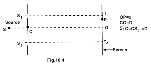
Ans: According to $\theta $ ,
\[X = D\] (Given)…..(I)
$d = 2D$
Path difference $p = \sqrt {{D^2} + {{\left( {x + \dfrac{d}{2}} \right)}^2}} - \sqrt {{D^2} + {{\left( {x - \dfrac{d}{2}} \right)}^2}} $
Substitute the value of \[d\] and \[x\] from I and II
$ = \sqrt {{D^2} + {{\left( {D + D} \right)}^2}} - \sqrt {{D^2} + {{\left( {D - D} \right)}^2}} $
$ = \sqrt {5{D^2}} - \sqrt {{D^2}} $
$p = D\left( {\sqrt 5 - 1} \right)$
The path difference for nth dark fringe from central maxima ‘O’ is $\left( {2n - 1} \right)\dfrac{\lambda }{2}$
$\therefore $ For 1st minima $p = \dfrac{\lambda }{2}$
Put the value of p in (III)
$\dfrac{\lambda }{2} = D\left( {\sqrt 5 - 1} \right)$
$D = \dfrac{\lambda }{{2\left( {\sqrt 5 - 1} \right)}}$
Rationalising the denominator, we get,
$D = \dfrac{\lambda }{{2\left( {\sqrt 5 - 1} \right)}} \times \dfrac{{\left( {\sqrt 5 + 1} \right)}}{{\left( {\sqrt 5 + 1} \right)}} = \dfrac{{\left( {2.236 + 1} \right)}}{{2 \times \left( {5 - 1} \right)}} = \dfrac{{3.236}}{{2 \times 4}}\lambda $
$ = \dfrac{{3.236}}{8}\lambda = 0.404\lambda $
LONG ANSWER TYPE
QUESTIONS
10.19 Figure 10.5 shown a two slit arrangement with a source which emits unpolarised light. P is a polariser with axis whose direction is not given. If \[{I_0}\] is the intensity of the principal maxima when no polariser is present, calculate in the present case, the intensity of the principal maxima as well as of the first minima.
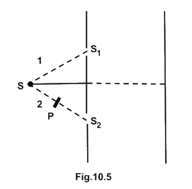
Ans: Let the amplitudes of ray 1 and 2 are and \[{A_1}\] respectively. \[{A_2}\] has constant phase difference $\phi $
${A_1} = A_ \bot ^1 + A_\parallel ^1$
${A_2} = A_ \bot ^2 + A_\parallel ^2$
Where,
\[A_ \bot ^1 = A_ \bot ^0\,\left( {\sin kx - \omega t} \right)\]
\[A_ \bot ^2 = A_ \bot ^0\left( {kx - \omega t + \phi } \right)\]
Maximum amplitude of \[{A_ \bot }\] and ${A_\parallel }$ are same $ = A_ \bot ^0$
$\therefore $Similarly for
$A_\parallel ^1 = A_\parallel ^0\,\sin \left( {kx - \omega t} \right)$
Where $A_\parallel ^2 = A_\parallel ^0\sin \left( {kx - \omega t + ?} \right)$
When ray 2 is polarized by P then it $A_\parallel ^2$ vector stopped.
\[ = {A_ \bot } + {A_\parallel } = \left[ {A_ \bot ^1 + A_ \bot ^2} \right] + \left[ {A_\parallel ^1 + A_\parallel ^2} \right]\]
\[ = \left[ {A_ \bot ^0\sin \left( {\omega t - kx} \right) + A_ \bot ^0\sin \left( {\omega t - kx + \phi } \right)} \right] + \left[ {A_\parallel ^0\sin \left( {\omega t + \phi } \right) + A_\parallel ^0\sin \left( {\omega t - kx + \phi } \right)} \right]....I\]
The amplitudes of \[{S_1}\] , \[{S_2}\] when there is no polarizer then perpendicular and parallel components are equal, as the wavefront is coming form same source \[S\] .
$\therefore A_ \bot ^1 = A_\parallel ^1 = A_ \bot ^2 = A_\parallel ^2 = {A_0}$
Where $A_ \bot ^1$ and $A_\parallel ^1$ are the amplitudes of electric and magnetic field vector respectively and $A_ \bot ^2$and $A_\parallel ^2$ are the amplitude of electric and magnetic field vector, respectively.
From equation I, we have$A = {A_0}\sin \left( {\omega t - kx} \right) + {A_0}\sin \left( {\omega t - kx + \phi } \right) + {A_0}\sin \left( {\omega t - kx} \right) + {A_0}\sin \left( {\omega t - kx + \phi } \right)$
$A = 2{A_0}\left[ {2\sin \omega t - kx + \sin \left( {\omega t - kx + \phi } \right)} \right].$
We know that the intensity of maxima in Young’s double slit experiment
$\therefore I = 2{I_0}\left( {I + \cos \phi } \right) = 2.KA_0^2\left( {1 + \cos \phi } \right)$
For maxima $\cos \phi = 1$
$I = 2kA_0^2\left( {1 + 1} \right) = 4KA_0^2$ Leaving the k (constant) then
$I = 4A_0^2$
Case II: When polariser P is placed in the path of ray 2: Let ${ \bot ^r}$ vector of ray 2 is blocked by polarizer
${A_1} = A_ \bot ^1 + A_\parallel ^1$
${A_2} = A_\parallel ^2\left( {\because A_ \bot ^2\,vector\,blocked} \right)$
$A = A_1^2 + A_2^2$
$I = {\left( {A_\parallel ^1 + A_\parallel ^2} \right)^2} + {\left| {A_ \bot ^1} \right|^2}$
${\left| {A_\parallel ^0} \right|_{a\nu }} = {\left| {A_ \bot ^0} \right|_{a\nu }} = {A_0}$
$I = kA_0^2\left( {1 + \cos } \right) + A_0^2\dfrac{1}{2}....\left( I \right)$
\[ = kA_0^2\left[ {\left( {1 + \cos \phi } \right) + \dfrac{1}{2}} \right]\]
\[ = kA_0^2\left[ {\dfrac{3}{2} + \cos \phi } \right]\left( {\cos \phi = 1\,for\,maxima} \right)\]
\[ = kA_0^2 \times \dfrac{5}{2}.....\left( {II} \right)\]
${I_0} = 4kA_0^2\,$ (When no polarization of ray 2)
$A_0^2 = \dfrac{{{I_0}}}{{4k}}....\left( {III} \right)$
Intensity of principal maxima with polarizer
$I = \dfrac{{{I_0}}}{4}\dfrac{5}{2}$ (From II and III)
$I = \dfrac{5}{8}{I_0}$
Intensity at the 1st minima \[\cos \phi = - 1\]
$\therefore I = {\left| {{A_0}} \right|^2}\left( {1 - 1} \right) + \dfrac{{A_0^2}}{2}$ [From I]
$I = \dfrac{{{I_0}}}{4} \cdot \dfrac{1}{2} = \dfrac{{{I_0}}}{8}$
10.20 A small transparent slab containing material of \[{\mathbf{\mu }} = {\mathbf{1}}.{\mathbf{5}}\] is placed along
\[{\mathbf{A}}{{\mathbf{S}}_2}\] (Fig.10.6). What will be the distance from O of the principal maxima and of the first minima on either side of the principal maxima obtained in the absence of the glass slab.
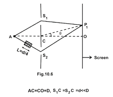
Ans: When ray \[A{S_2}\] passes through glass slab of thickness L and refractive index $\mu $ the path difference caused by slab is \[\left( {\mu \; - 1} \right)L\] and path difference caused by Young’s double slit experiment is \[2d\;\sin \theta \] . Total path difference at \[{P_2}\] is
$\therefore \Delta x = 2d\sin \theta + \left( {\mu - 1} \right)L$
For principal maxima, path difference $\Delta x = 0$
$2d\sin {\theta _0} + \left( {\mu - 1} \right)\,L = 0$ (For central maxima \[\theta = {\theta _0}\] )
$\sin {\theta _0} = \dfrac{{ - \left( {\mu - 1} \right)L}}{{2d}} = \dfrac{{ - (1.5 - 1)L}}{{2 \times 4L}}\left[ {as\,L = \dfrac{d}{4},\,d = 4L} \right]$
$\sin {\theta _0} = \dfrac{{ - 0.5 \cdot L}}{{2 \times 4L}} = \dfrac{{ - 1}}{{16}}$
For central maxima, $OP = D\tan {\theta _0} \approx D\sin {\theta _0} = \dfrac{{ - D}}{{16}}$
For small $\angle {\theta _0},\,\sin {\theta _0} = {\theta _0}\,and\,\tan {\theta _0} = {\theta _0}$
For the first minima the path difference $ = \dfrac{{ + \lambda }}{2}$
\[x_2^ - \] (For both upper and lower side from O]
$\therefore 2d\sin {\theta _1} + \left( {\mu - 1} \right)L = \dfrac{{ \pm \lambda }}{2}$
$2d\sin {\theta _1} = \dfrac{{ \pm \lambda }}{2} - 0.5\left( {\because L = \dfrac{d}{4}} \right)$
$\sin {\theta _1} = \dfrac{{\dfrac{{ \pm \lambda }}{2} - 0.5\dfrac{d}{4}}}{{2d}} = \dfrac{{\dfrac{{ \pm \lambda }}{2} - \dfrac{d}{8}}}{{2d}}$
$\sin {\theta _1} = \dfrac{{\dfrac{{\left( { \pm 4\lambda - d} \right)}}{8}}}{{2d}}$
For diffraction, \[\lambda = d\] (half the slit dist.)
$\therefore \sin {\theta _1} = \dfrac{{\left( { \pm 4\lambda - \lambda } \right)}}{{16\lambda }} = \dfrac{{\left( { \pm 4\lambda - 1} \right)\lambda }}{{16\lambda }}$
$\sin {\theta _1} = \dfrac{{ \pm 4 - 1}}{{16}}$
For positive direction side, \[\sin \theta _1^ + = \dfrac{3}{{16}}\]
For negative direction side, \[\sin \theta _1^ - = \dfrac{{ - 5}}{{16}}\]
The distance of first minima from principal maxima on either side \[x_1^ + \] and \[x_2^ - \] , are
$x_1^ + = D\tan \theta _1^ + = D \cdot \dfrac{{\sin \theta _1^ + }}{{\cos \theta _1^ + }}$
$x_1^ + = D\tan \theta _1^ + = D\dfrac{{\sin \theta _1^ + }}{{\sqrt {\left( {1 - {{\sin }^2}\theta _1^ + } \right)} }} = \dfrac{{D\dfrac{3}{{16}}}}{{\sqrt {1 - \dfrac{{ - 9}}{{256}}} }}$
$x_1^ + = D\tan {\theta _1} = \dfrac{{\dfrac{{3D}}{{16}}}}{{\dfrac{{\sqrt {256 - 9} }}{{16}}}} = \dfrac{{3D}}{{\sqrt {247} }}$ [Above point O on screen]
The first minima starts after the end of central maxima. So the Ist minima starts at distance of \[D = \tan \theta = x_1^ + = \dfrac{{3D}}{{\sqrt {247} }}\] above O in positive direction.
The distance of first minima on the negative side is
$x_1^ - = \dfrac{{D\sin \theta _1^ - }}{{\sqrt {1 - {{\sin }^2}\theta _1^ - } }} = \dfrac{{\dfrac{{ - 5D}}{{16}}}}{{\dfrac{{\sqrt {{{16}^1} - {5^2}} }}{{16}}}}$
$x_1^ - = \dfrac{{ - 5D}}{{\sqrt {256 - 25} }}\dfrac{{ - 5D}}{{\sqrt {231} }}$
10.21 Four identical monochromatic sources A,B,C,D as shown in the (Fig.10.7) produce waves of the same wavelength \[\lambda \] and are coherent. Two receiver \[{R_1}\] and \[{R_2}\]are at great but equal distances from B.
(i) Which of the two receivers picks up the larger signal?
(ii) Which of the two receivers picks up the larger signal when B is turned off?
(iii) Which of the two receivers picks up the larger signal when is turned off?
(iv) Which of the two receivers can distinguish which of the sources B or D has been turned off?
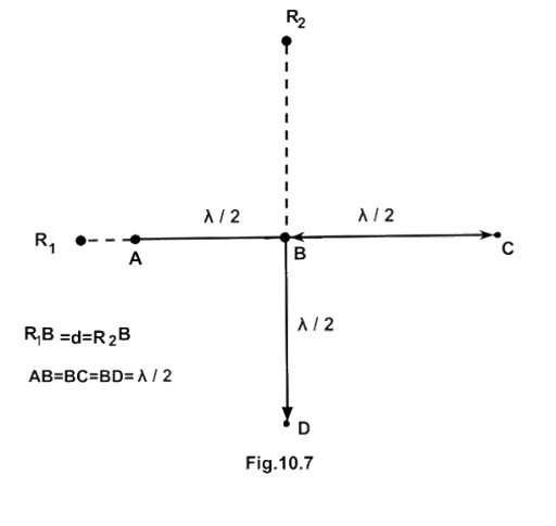
Ans: Consider all the disturbance at ${R_1}$
Let the wave from source A has zero path difference at ${R_1}$
\[\therefore yA = a\,cos\,\omega t\]
Path diff. between A and B is \[\dfrac{\lambda }{2}\] or π so wave of B at ${R_1}$ is \[yB{\text{ }} = - a{\text{ }}cos{\text{ }}\omega t\]
Path difference between wave A and C is $\lambda $ or \[2\pi \] .
So the wave from source C is
${y_c} = a\cos \left( {\omega t - 2\pi } \right)$
$or,{y_c} = a\cos \omega t$
Path difference between A and D $ = {R_1}D - A{R_1}$
$ = \sqrt {{d^2} + {{\left( {\dfrac{\lambda }{2}} \right)}^2}} - \left( {d - \dfrac{\lambda }{2}} \right) = {\left( {{d^2} + \dfrac{{{\lambda ^2}}}{4}} \right)^{\dfrac{1}{2}}} - d + \dfrac{\lambda }{2}$
$ = d{\left[ {1 + \dfrac{{{\lambda ^2}}}{{4{d^2}}}} \right]^{\dfrac{1}{2}}} - d + \dfrac{\lambda }{d} = d\left[ {1 + \dfrac{{{\lambda ^2}}}{{8{d^2}}}} \right] - d + \dfrac{\lambda }{2}$
Neglecting the term $\dfrac{{{\lambda ^2}}}{{8{d^2}}},\left( {\because {\lambda ^2} < < 8{d^2}} \right)$
Path difference between A and D $ = d + 0 - d + \dfrac{\lambda }{2} = \dfrac{\lambda }{2}or\,\pi $
$\therefore {y_D} = a\cos (\omega t - \pi ) = - a\cos \omega t$
$ = a\cos \omega t - a\cos \omega t + a\cos \omega t - a\cos \omega t$
${y_{{R_1}}} = 0\,so\left\langle {{I_{{R_1}}}} \right\rangle \approx 0$
So resultant signal at ${R_1}$ due to A, B, C and D sources is zero or no signal.
(i) New distance \[B{R_2} = d\]
Let the signal picked up by \[{R_2}\] from \[B = {a_1}{\text{ }}cos{\text{ }}\omega t\]
The path diff. between B and D$ = \dfrac{\lambda }{2}$ or \[\pi \] so
\[Path\,\,diference = \sqrt {{d^2} + {{\left( {\dfrac{\lambda }{2}} \right)}^2}} - d\]
\[\Delta x = {\left[ {{d^2} + \dfrac{{{\lambda ^3}}}{4}} \right]^{\dfrac{1}{2}}} - d = d\left[ {1 + \dfrac{\lambda }{{8{d^2}}}} \right] - d\]
\[\therefore \Delta x = d + \dfrac{{d{\lambda ^2}}}{{8{d^2}}} - d = \dfrac{{{\lambda ^2}}}{{8d}}\]
Phase difference $ = \dfrac{{2\pi }}{\lambda }\Delta x = \dfrac{{2\pi }}{\lambda } \cdot \dfrac{{{\lambda ^2}}}{{8d}} = \dfrac{{2\pi \lambda }}{{8d}} = \phi $
So the signals received by \[{R_2}\] from A and C are
${y_A} = a\cos \left( {\omega t - \phi } \right)$
${y_c} = a\cos \left( {\omega t - \phi } \right)$
Signals picked up by \[{{\text{R}}_2}\] from A, B, C and D
${y_{{R_2}}} = {y_A} + {y_B} + {y_C} + {y_D}$
$ = a\cos \left( {\omega t - \phi } \right) + a\cos \omega t + a\cos \left( {\omega t - \phi } \right) - a\cos \omega t$
$ = 2a\cos \left( {\omega t - \phi } \right)\left( {\because \left\langle I \right\rangle = \dfrac{1}{2}{{\left( a \right)}^2}} \right)$
$\left\langle {{I_{{R_2}}}} \right\rangle = \dfrac{1}{2}\left[ {4{a^2}} \right] \Rightarrow \left\langle {{I_{{R_2}}}} \right\rangle = 2{a^2}\left( {\because I = {A^2}} \right)$
Thus, \[{{\text{R}}_2}\] picks up the larger signal than\[{R_1}\] .
(ii) If B is switched off,
(a) signals picked up by
${R_1} = {Y_A} + {Y_C} + {Y_D}$
${R_1} = a\cos \omega t + a\cos \omega t - a\cos \omega t = a\cos \omega t$
$\therefore {\left( {{I_{{R_1}}}} \right)_{a\nu }} = \dfrac{1}{2}{a^2}.....\left( I \right)$
(b) Signals picked up by
\[{R_2} = {y_A} + {y_C} + {y_D}\]
\[ = a\cos \left( {\omega t - \phi } \right) + a\cos \omega t - a\cos \omega t = a\cos \omega t\]
Net signals at
\[{R_2} = 2a\cos \left( {\omega t - \phi } \right) - a\cos \left( {\omega t} \right) = a\left[ {2\cos \left( {\omega t - \phi } \right) - \cos \left( {\omega t} \right)} \right]\]
\[\left\langle {{I_{{R_2}}}} \right\rangle = \dfrac{{{a^2}}}{2}.....\left( {II} \right)\]
\[\left\langle {{I_{{R_1}}}} \right\rangle = \left\langle {{I_{{R_2}}}} \right\rangle \]
So \[{R_1}\] and \[{R_2}\] picks up the signals of the same intensities.
(iii) If D is switched off
(a) Signals picked up by receiver \[{R_1}\]
${R_1} = {y_B} + {y_C} + {y_A} = - a\cos \omega t + a\cos \omega t + a\cos \omega t$
${y_{{R_1}}} = a\cos \omega t$
$\therefore \left\langle {{I_{{R_1}}}} \right\rangle = \dfrac{1}{2}{a^2}$
(b) Signals picked up by receiver \[{R_2}\]
${R_2} = {y_A} + {y_B} + {y_C}$
$ = a\cos \left( {\omega t - \phi } \right) + a\cos \omega t + a\cos \left( {\omega t - \phi } \right)$
$ = 2a\cos \left( {\omega t - \phi } \right) + a\cos \omega t$
$\therefore \dfrac{{2\pi \lambda }}{a} = \phi \,$is very small so can be neglected.
So signal received by
${R_2} = 2a\cos \omega t + a\cos \omega t = 3a\cos \omega t$
$\left\langle {{I_{{R_2}}}} \right\rangle = \dfrac{{9{a^2}}}{2}$
$\left\langle {{I_{{R_1}}}} \right\rangle < \left\langle {{I_{{R_2}}}} \right\rangle $
So \[{R_2}\] picks up larger signal compared to\[{R_1}\] .
(iv) A signal at \[{R_1}\] indicates that B has been switched off.
A signal at \[{R_2}\] indicates that D has been switched off.
10.22 The optical properties of a medium are governed by the relative permittivity $\left( {{\varepsilon _r}} \right)$and relative permeability \[\left( {\mu r} \right)\] . The refractive index is defined as $\sqrt {{\varepsilon _r}{\mu _r}} = \mu $ . For ordinary material \[{\varepsilon _r} > 0\] and \[\mu r > 0\] and the positive sign is taken for the square root. In1964, a Russian scientist V. Veselago postulated the existence of material with \[{\varepsilon _r} < 0\] and \[{\mu _r} < 0\] . Since then such ‘metamaterials’ have been Produced in the laboratories and their optical properties studied. For such materials $\mu = - \sqrt {{\mu _r}{\varepsilon _r}} $ . As light enters a medium of such refractive index the phases travel away from the direction of propagation.
Ans: (i) According to the description above show that if rays of light enter such a medium from air (refractive index =1) at an angle \[\theta \] in 2nd quadrant, them the refracted beam is in the 3rd quadrant.
(ii) Prove that Snell’s law holds for such a medium.
Ans: (i) Let the postulates $ - \sqrt {{\mu _r}{\varepsilon _r}} = \mu $ and $ + \sqrt {{\mu _r}{\varepsilon _r}} = \mu $ are true then two parallel rays would proceed as shown in figure (a) and figure (b) respectively.
Let two parallel rays at incidence angle ${\theta _i}$ from air would proceed in medium as shown in figures above. ED shows a wavefront, then all the points on ED will remain in same phase. All the points with the same optical path length must have the same phase.
So,
$ - \sqrt {{\mu _r}{\varepsilon _r}} AE = BC - \sqrt {{\mu _r}{\varepsilon _r}} CD$
$BC = \sqrt {{\mu _r}{\varepsilon _r}} \left( {CD - AE} \right)$
$BC > 0;CD > AE$
As showing that the postulate is reasonable if however, the light proceeded in the sense it does for ordinary material e.g., refracted rays are in IV quadrant in figure (b) then
$ - \sqrt {{\varepsilon _r}{\mu _r}} AE = BC - \sqrt {{\mu _r}{\varepsilon _r}} CD$
$BC = \sqrt {{\mu _r}{\varepsilon _r}} \left( {CD - AE} \right)$
\[AE > CD\] hence \[BC < {\text{ }}0\]
Figure showing that \[BC < {\text{ }}0\] this is not possible. Hence the given postulate is correct.
(ii) From fig. (a)
$BC = AC\sin {\theta _i}$
$CD - AE = AC\sin {\theta _r}$
$BC = \sqrt {{\mu _r}{\varepsilon _r}} $
$AC\sin {\theta _i} = \sqrt {{\mu _r}{\varepsilon _r}} AC\sin {\theta _r}$
$\dfrac{{\sin {\theta _i}}}{{\sin {\theta _r}}} = \sqrt {{\mu _r}{\varepsilon _r}} $
Which proves the Snell’s law.
10.23 To ensure almost 100 percent transitivity, photographic lenses are often coated with a thin layer of dielectric material. The refractive index of this material is intermediated between that of air and glass (which makes the optical element of the lens). A typically used dielectric film is\[Mg{F_2}\left( {n = 1.38} \right)\]. What should the thickness of the film be so that at the center of the visible spectrum \[\left( {5500\mathop A\limits^ \circ \;} \right)\]there is maximum transmission.
Ans: In the given figure incidence ray IA incident at point A from air to film surface with incident angle i. here at A, it gets partial reflection and refraction, passes through paths
\[A{R_1}\] glass and film interface surface. At C the interface surface of film and air and finally after refraction from C pass-through path \[C{R_2}\] parallel to \[A{R_1}\] . The amplitude (intensity) of wave during refraction and reflection decreases.
If the interference due to two reflected rays \[A{R_1}\] and \[C{R_2}\] is destructive interference, then the reflected rays AR, and \[C{R_2}\] will not dominant.
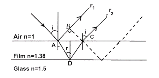
Both reflections are from lower to higher refractive index surfaces So, optical path difference between \[A{R_1}\] and \[C{R_2}\] will be
$\mu \left( {AD + CD} \right) - AB...\left( I \right)$
$AD = AC = \dfrac{d}{{\cos r}}...\left( {II} \right)$
$AB = AC\sin i$
$or,\tan r = \dfrac{{\dfrac{{AC}}{2}}}{d}$
$\therefore d\tan r = \dfrac{{AC}}{2}$
$AC = 2d\tan r$
$or,AB = 2d\tan r\sin i......\left( {III} \right)$
So the optical path difference from (I)
\[ = \mu AD + \mu AD - AB\left( {\because AD = CD} \right)\]
\[ = 2\mu AD - AB\]
\[ = \dfrac{{2\mu d}}{{\cos r}} - 2d\tan r\sin i\] (From II and III)
$2 \cdot \dfrac{{\sin i}}{{\sin r}} \cdot \dfrac{d}{{\cos r}} - 2d\dfrac{{\sin r}}{{\cos r}} \cdot \sin i = \dfrac{{2d\sin i}}{{\cos r}}\left[ {\dfrac{1}{{\sin r}} - \dfrac{{\sin r}}{1}} \right]$
$ = \dfrac{{2d\sin i\left( { - {{\sin }^2}r} \right)}}{{\cos r\sin r}} = \dfrac{{2d\sin i{{\cos }^2}r}}{{\sin r\cos r}}$
Optical path difference between \[A{R_1}\] and \[A{R_2}\]
$2d\mu \cdot \cos r\left( {\because \mu = \dfrac{{\sin i}}{{\sin r}}} \right)$
For two rays \[A{R_1}\] and \[C{R_2}\] to interfere destructively, path difference should be$\therefore 2d\mu \cos r = \dfrac{\lambda }{2}$
$\mu d\cos r = \dfrac{\lambda }{4}$
For photographic lenses the sources are vertical planes i.e., rays incident at very small angle.
So,
$i = r \approx o$
$\therefore \mu d \approx \dfrac{\lambda }{4}\left( {\because \cos 0 = 1} \right)$
$d = \dfrac{\lambda }{{4\mu }} = \dfrac{{5500\mathop A\limits^ \circ }}{{1.38}}$
$d = 1000\mathop A\limits^ \circ $
NCERT Exemplar for Class 12 Physics - Wave Optics
Vedantu's NCERT Exemplar for Class 12 Physics Chapter 10 - Wave Optics is created with only one goal in mind, to help Class 12 students get a deeper understanding of Chapter 10 (Wave Optics). That's because Chapter 10 is one of the most important chapters in the NCERT Physics textbook that students can learn to achieve good grades.
Students who have any weaknesses related to this chapter can be benefited the most from NCERT Exemplar for Class 12 Physics Chapter 10 - Wave Optics. That's because the solutions given in the study material are specifically designed for students who have less interest in this topic. The solutions are simplified and made easier for those students to quickly understand and remember.
Also, the students who are interested in this topic and feel like this topic is easy for them if they can get a good study supply too can find Vedantu's NCERT Exemplar for Class 12 Physics Chapter 10 - Wave Optics valuable and interesting.
Chapter 10 - Wave Optics introduces the study of several phenomena like:
Polarization
Diffraction
Interference, and much more
Introduction to Chapter
This chapter explains the behaviour of light under various phenomena. "Wave optics" is a name given to the characteristics of its waves.
The first part of NCERT Exemplar for Class 12 Physics Chapter 10 - Wave Optics contains 9 questions in total, these questions are in the form of multiple-choice questions. The second part includes similar contents as the first part.
Although from the third part, students are asked questions for which they are expected to give brief answers. In the fourth part, students should answer the questions with short/medium-sized answers. These questions are established on the principle of Huygens'. It also discusses its construction.
DESM (Department of Education in Science and Mathematics) have formulated the questions provided in NCERT Exemplar for Class 12 Physics Chapter 10 - Wave Optics which are designed to test students with several types of difficulty levels. This fact makes these questions extremely important from the examination point of view.


FAQs on NCERT Exemplar for Class 12 Physics Chapter-10 (Book Solutions)
1. Does Vedantu charge for its NCERT Exemplar for Class 12 Physics?
To answer this question in one word, No. Vedantu is trying to make important study material easily accessible to as many students as possible. That's because this is the best way to help young folk learn and prosper. That's why most of the study materials found on Vedantu's website and mobile app are completely free of cost. Students of Class 12 don't have to pay anything to download and access the study materials Vedantu shares. Which contains the NCERT Exemplar for Class 12 Physics Chapter 7 Integrals.
2. Is Chapter 10 (wave optics) in the NCERT Exemplar for Class 12 Physics difficult to grasp?
No, Chapter 10 (Wave Optics) in the NCERT Exemplar for Class 12 Physics is not tough for most of the students. Rather, it is admitted to be one of the most interesting and the easiest chapters by most of the former students. Also, from NCERT's point of view, this chapter holds a great amount of importance in the Class 12 annual examination for Physics. Although some students who might not be interested in this topic can find this a bit tough, they can easily understand it by learning from the NCERT example for Class 12 Physics provided by Vedantu.
3. How is the NCERT Exemplar for Class 12 Physics created?
Vedantu has a board of Physics experts to develop the study materials that students can download and benefit from. These study materials are created by the experts who have a deeper understanding of the paper pattern and regulations CBSE follows for creating their own question papers. These NCERT examples for Class 12 Physics are available free of cost across all of Vedantu's websites and even on the app for mobile and tablet. Students can download them and start studying right away so that they can be prepared for the Class 12 Physics examination.
4. Can Vedantu's NCERT Exemplar for class 12 Physics really help me score well?
Yes. Studying NCERT Exemplar for Class 12 Physics will help students score better in CBSE Class 12 annual examination. That's because you will be ready for any highly crucial question that has considerable odds of coming up in the examination. These solutions are prepared by experts at Vedantu. So studying these will definitely help you focus on the important topics more. Meaning, you can stop wasting time memorizing unimportant topics. Also, practicing these solutions on a regular basis will help students score well in their annual examination by gaining the necessary confidence.
5. How do I start preparing for the CBSE Class 12 Physics annual examination?
You can start preparing for the CBSE Class 12 Physics annual examination by analyzing each chapter deeply. You can even start revising and making notes of the important topics that you think are going to appear in the examination. And lastly, you can download the provided NCERT Exemplar for Class 12 Physics. Doing all of this simultaneously will prepare you for the annual examination in an amazing manner. Consider downloading these free study materials and take full advantage of them to score higher in the annual exams.