


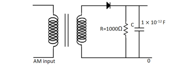
In the given detector circuit, the suitable value of carrier frequency is :-
(A) $ \ll {10^9}Hz$
(B) $ \ll {10^5}Hz$
(C) $ \gg {10^9}Hz$
(D) None of these.
Answer
232.8k+ views
Hint: In this detector circuit, using the values for the resistance and the capacitance, we can find their product. Now using the condition for the carrier frequency in detector circuit that is, $\dfrac{1}{{{f_c}}} \ll RC$, we can find the suitable value of the carrier frequency.
Formula UsedIn this solution we will be using the following formula,
$\dfrac{1}{{{f_c}}} \ll RC$
where ${f_c}$ is the carrier frequency,
$R$ is the resistance and
$C$ is the capacitance
Complete Step by Step Solution
For a detector circuit, the carrier frequency, the resistance and the capacitance are all related by the formula,
$\dfrac{1}{{{f_c}}} \ll RC$
Now we can take reciprocal on both the sides. So we will get,
${f_c} \gg \dfrac{1}{{RC}}$
The inequality sign also gets reversed on taking the reciprocal.
Now we are given in the diagram in the question that the resistance has a value,
$R = 1000\Omega $
And the capacitance is given as,
$C = 1 \times {10^{ - 12}}F$
Therefore, the RHS of the previous equation is the product of the resistance and capacitance. So n doing the product we get,
$R \times C = 1000 \times 1 \times {10^{ - 12}}$
So this gives us a value of,
$R \times C = {10^{ - 9}}$
Therefore, we can substitute this value in the equation and get,
${f_c} \gg \dfrac{1}{{{{10}^{ - 9}}}}$
Hence this becomes,
${f_c} \gg {10^9}Hz$
So the carrier frequency should have a suitable value of $ \gg {10^9}Hz$
So the correct answer is option C.
NoteThe carrier frequency is the frequency of the carrier wave that is modulated to transmit signals.
A carrier signal is used for efficient transmission in order to reduce the wavelength. The carrier signal is usually a simple single frequency sinusoid. A detector circuit is used to extract information from a modulated radio frequency current or voltage.
Recently Updated Pages
Circuit Switching vs Packet Switching: Key Differences Explained
JEE General Topics in Chemistry Important Concepts and Tips
JEE Extractive Metallurgy Important Concepts and Tips for Exam Preparation
JEE Amino Acids and Peptides Important Concepts and Tips for Exam Preparation
JEE Atomic Structure and Chemical Bonding important Concepts and Tips
Electricity and Magnetism Explained: Key Concepts & Applications
Trending doubts
JEE Main 2026: Session 2 Registration Open, City Intimation Slip, Exam Dates, Syllabus & Eligibility
JEE Main 2026 Application Login: Direct Link, Registration, Form Fill, and Steps
JEE Main Marking Scheme 2026- Paper-Wise Marks Distribution and Negative Marking Details
Understanding the Angle of Deviation in a Prism
Hybridisation in Chemistry – Concept, Types & Applications
How to Convert a Galvanometer into an Ammeter or Voltmeter
Other Pages
JEE Advanced Marks vs Ranks 2025: Understanding Category-wise Qualifying Marks and Previous Year Cut-offs
Dual Nature of Radiation and Matter Class 12 Physics Chapter 11 CBSE Notes - 2025-26
Understanding Uniform Acceleration in Physics
Understanding the Electric Field of a Uniformly Charged Ring
JEE Advanced Weightage 2025 Chapter-Wise for Physics, Maths and Chemistry
Derivation of Equation of Trajectory Explained for Students