


Class 10 Science Chapter 12 Questions and Answers with Solutions
Vedantu provides NCERT Solutions for magnetic effects of electric current class 10, a key resource for students who want to navigate the concepts of Science at the 10th-grade level. Students will learn about the concepts related to this chapter, such as magnetic field and field lines, magnetic field due to current carrying conductor, etc.
 Table of Content
Download the FREE PDF of Class 10 Science NCERT Solutions for magnetic effects of electric current class 10 questions and answers, which are prepared by Vedantu master teachers and updated according to the CBSE Class 10 Science Syllabus and exam pattern.
Glance on Class 10 Science Chapter 12 NCERT Solutions
The magnetic effects of electric current class 10 emphasise that electricity and magnetic effect or magnetism are related.
In class 10, magnetic effects of electric current solutions, students will learn about the magnetic field as a quantity with magnitude and directional properties.
Magnetic effects of electric current question answers can help see the direction of a magnetic field.
Topics like magnetic fields and how they are produced by moving charges, such as electric currents, and the concept of magnetic field lines are well discussed.
Students may expect short-answer questions, long-answer type questions, and multiple-choice questions from magnetic effects of electric current NCERT solutions in the CBSE Term II Class 10 Science exam.
The answers to the questions in class 10 science chapter 12 will help you clear your concepts about the topic with easily graspable discussions on why a compass needle deflects when brought near a bar magnet.
NCERT Solutions For Class 10 Science Chapter 12 Magnetic Effects Of Electric Current - 2026-27
Intext Exercise 1
1. Why does a compass needle get deflected when brought near a bar magnet?
Ans: A compass needle is basically a small bar magnet. When it is brought closer to a bar magnet, its magnetic field lines would interact with the bar magnet. Therefore, a compass needle shows a deflection on being brought near the bar magnet.
Intext Exercise 2
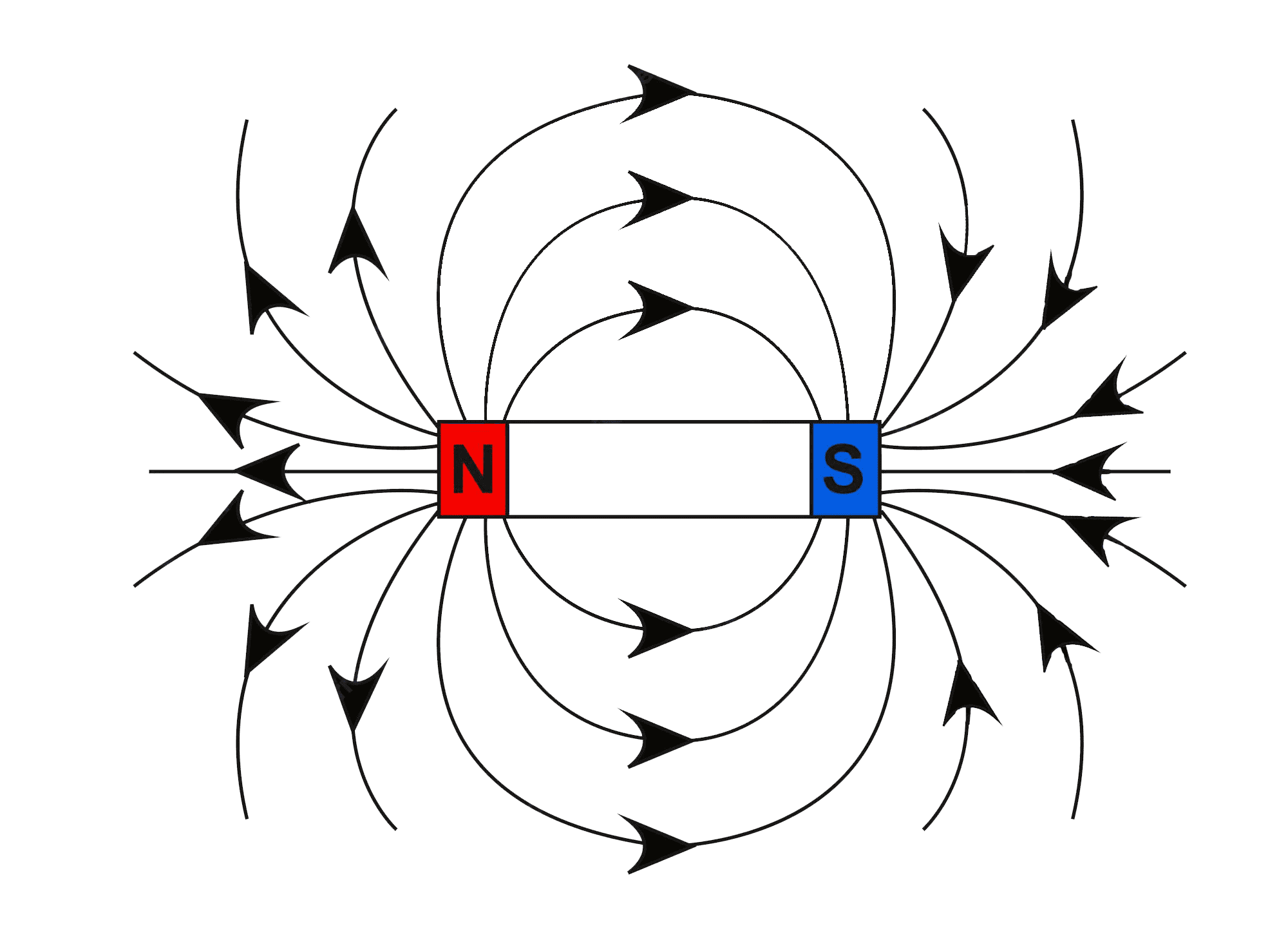
1. Draw magnetic field lines around a bar magnet.
Ans: We know that, magnetic field lines of a bar magnet emerge from the north pole and will terminate at the south pole. And the field lines would emerge from the south pole inside the magnet and would terminate at the north pole, which can be seen in the below figure.
2. List the properties of magnetic lines of force.
Ans: The properties of magnetic lines of force are known to be as follows:
1. Magnetic field lines are known to arise from the north pole.
2. Magnetic field lines will always terminate at the south pole.
3. The direction of field lines inside the magnet is known to be from the south pole to the north pole.
4. Magnetic lines do not intersect each other.
3. Why don’t two magnetic lines of force intersect each other?
Ans: When two field lines of a magnet intersect, the compass needle would point in two different directions at the point of intersection, which we know is impossible. Therefore, we could conclude that the two field lines do not intersect each other.
Intext Exercise 3
1. Consider a circular loop of wire lying in the plane of the table. Let the current pass through the loop clockwise. Apply the right-hand rule to find out the direction of the magnetic field inside and outside the loop.
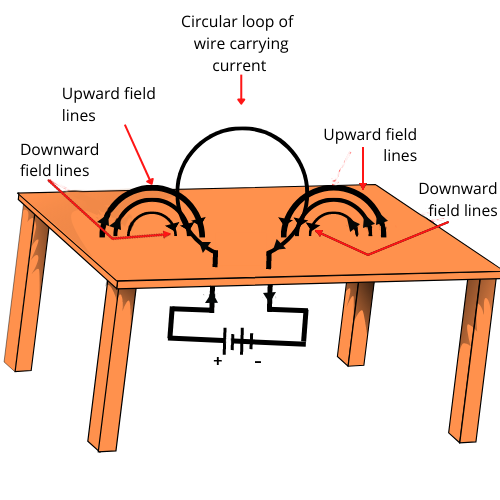
Ans: We can see that, Inside the loop = Pierce inside the table
Outside the loop = Appear to emerge out from the table
For downward direction of current flowing in the circular loop, the direction of magnetic field lines can be seen to be as if they are emerging from the table outside the loop and merging in the table inside the loop. Similarly, for the upward direction of the current flowing through the circular loop, the direction of magnetic field lines can be seen to be as if they are emerging from the table outside the loop and merging in the table inside the loop, as shown in the given figure.
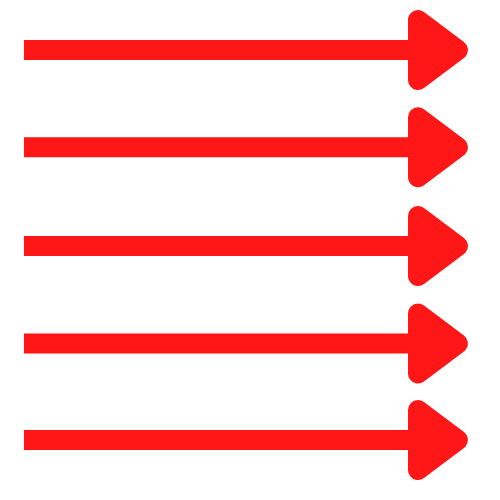
2. The magnetic field in a given region is uniform. Draw a diagram to represent it.
Ans: Uniform magnetic field could be represented by the parallel straight lines.
3. Choose the correct option.
The magnetic field inside a long straight solenoid-carrying current
a. Is zero
b. Ddecreases as we move towards its end
c. Increases as we move towards its end
d. Is the same at all points
Ans: The correct option is (d). The magnetic field inside a long, straight, current-carrying solenoid is found to be uniform. Inside the solenoid it would be the same at all points.
Intext Exercise 4
1.Which of the following properties of a proton can change while it moves freely in a magnetic field? (There may be more than one correct answer.)
a. Mass
b. Speed
c. Velocity
d. Momentum
Ans: The correct options are (c) and (d).
When a proton enters a magnetic field area, it would experience a magnetic force. As a result of this force, the path of the proton would become circular. Therefore, its velocity and momentum would also change.
2. In Activity 13.7 (page: 230), how do we think the displacement of rod AB will be affected if (i) current in rod AB is increased; (ii) a stronger horse-shoe magnet is used; and (iii) length of the rod AB is increased?
Ans: We know that in a magnetic field, a current-carrying conductor would experience a force. The magnitude of this force would increase with the amount of current, the magnetic field strength and the length of the conductor. So, the magnetic force exerted on rod AB and its deflection would increase if:
i. current in rod AB is increased
ii. a stronger horse-shoe magnet is used
iii. length of rod AB is increased
3. A positively-charged particle (alpha-particle) projected towards west is deflected towards north by a magnetic field. The direction of the magnetic field is:
a. Towards South
b. Towards East
c. Downward
d. Upward
Ans: The correct option is (d). Using Fleming's left-hand rule, the direction of the magnetic field could be easily determined. As per this rule, stretch the thumb, forefinger and middle finger of your left hand such that they are mutually perpendicular. If the first finger points in the direction of the magnetic field and the second finger in the direction of current, then the thumb would point in the direction of motion, that is, the direction of the force acting on the conductor.
Since the direction of a positively charged alpha particle is given to be towards west, the direction of current will be the same i.e., towards west. And, the direction of the magnetic force is towards north. Therefore, according to Fleming’s left-hand rule, the magnetic field will be directed upwards
Intext Exercise 5
1. State Fleming’s left-hand rule.
Ans: Fleming’s left hand rule states that: Stretch the thumb, forefinger and middle finger of your left hand such that they are mutually perpendicular. If the first finger points in the direction of the magnetic field and the second finger in the direction of current, then the thumb would point in the direction of motion or the force acting on the conductor.
2. What is the principle of an electric motor?
Ans: An electric motor’s working principle is known to be based on the magnetic effect of current. A current-carrying loop would experience a force and would rotate when placed in a magnetic field. The direction of rotation of the loop could be provided by Fleming's left-hand rule.
3. What is the role of the split ring in an electric motor?
Ans: The split ring keeps the motor rotating in the same direction. The split ring in the electric motor also acts as a commutator. The commutator reverses the direction of current flowing through the coil after each half rotation of the coil. Due to this reversal of the current, the coil would continue to rotate in the same direction.
Intext Exercise 6
1.Explain different ways to induce a current in a coil.
Ans: The different ways to induce a current in a coil are as follows:
(a) An electric current is induced in the coil, if a coil is moved rapidly between the two poles of a horse-shoe magnet.
(b) And if a magnet is moved relative to a coil,
Intext Exercise 7
1. State the principle of an electric generator.
Ans: An electric generator works based on the principle of electromagnetic induction. An electric generator is known to generate electricity by rotating a coil in a magnetic field.
2. Name some sources of direct current.
Ans: Cell, DC generator, etc are some sources of direct current.
3. Which sources produce alternating current?
Ans: AC generators, power plants, etc. can produce alternating current.
4. Choose the correct option.
A rectangular coil of copper wire is rotated in a magnetic field. The direction of the induced current changes once in each
a. Two Revolutions
b. One Revolution
c. Half Revolution
d. One-Fourth Revolution
Ans: The correct option is (c). When a rectangular coil of copper is rotated in a magnetic field, the direction of the induced current in the coil would change once in each half revolution.
Intext Exercise 8
1. Name two safety measures commonly used in electric circuits and appliances.
Ans: Two safety measures commonly used in electric circuits and appliances are listed as follows:
i. An electric fuse must necessarily be connected to each circuit. This would prevent the flow of excessive current through the circuit. When the current passing through the wire exceeds the maximum limit of the fuse element, the fuse would melt to stop the excess flow of current through that circuit, thus protecting the appliances connected to the circuit.
ii. In order to prevent shocks, earthing is considered an important safety measure. Any leakage of current in an electric appliance could be transferred to the ground and people using the appliance do not get the shock.
2. An electric oven of 2 kW is operated in a domestic electric circuit (220 V) that has a current rating of 5 A. What result do you expect? Explain.
Ans: Current drawn by the electric oven could be obtained by the expression,
$P=V\times I$
Where, I is the Current.
We are given: Power of the oven, \[P=2\text{ }kW=2000W\]
Voltage supplied, \[V\text{ }=\text{ }220\text{ }V\]
$\Rightarrow I=\frac{P}{V}=\frac{2000}{220}$
\[\Rightarrow I\text{ = }9.09\text{ }A\]
Hence, the current drawn by the electric oven is found to be 9.09 A, which exceeds the safety limit of the circuit. So, the fuse element of the electric fuse would melt and hence break the circuit.
3. What precautions should be taken to avoid the overloading of domestic electric circuits?
Ans: Following precautions should be taken in order to avoid the overloading of domestic circuits:
i. Too many appliances shouldn’t be connected to a single socket.
ii. Too many appliances shouldn’t be used simultaneously.
iii. Fuse must be connected to the circuit.
iv. Faulty appliances shouldn’t be connected into the circuit.
NCERT Exercise
1.Which of the following correctly describes the magnetic field near a long straight wire?
a. The field consists of straight lines perpendicular to the wire
b. The field consists of straight lines parallel to the wire
c. The field consists of radial lines originating from the wire
d. The field consists of concentric circles centred on the wire
Ans: The correct option is (d). The magnetic field lines, produced around a straight current-carrying conductor, are always in concentric circles. Their centres would lie on the wire.
2. The phenomenon of electromagnetic induction is
a. The process of charging a body
b. The process of generating a magnetic field due to a current passing through a coil.
c. Producing induced current in a coil due to relative motion between the magnet and the coil.
d. The process of rotating a coil of an electric motor
Ans: The correct option is (c). When a straight coil and a magnet are moved relative to each other, a current would be induced in the coil. This phenomenon is known to be electromagnetic induction.
3. The device used for producing electric current is called a
a. Generator
b. Galvanometer
c. Ammeter
d. Motor
Ans: The correct option is (a). An electric current is produced by an electric generator. It would convert mechanical energy into electricity.
4. The essential difference between an AC generator and a DC generator is that:
a. AC generator has an electromagnet while a DC generator has permanent magnet.
b. DC generator will generate a higher voltage.
c. AC generator will generate a higher voltage.
d. AC generator has slip rings while the DC generator has a commutator.
Ans: The correct option is (d). An AC generator has two rings that are called slip rings whereas a DC generator has two half rings called commutators. This is known to be the main difference between both the types of generators.
5. At the time of short circuit, the current in the circuit
a. Reduces Substantially
b. Does not change
c. Increases Heavily
d. Vary Continuously
Ans: The correct option is (c). When two naked wires of an electric circuit touch each other, the amount of current flowing through the circuit would increase abruptly. This would in turn cause a short-circuit.
6. State whether the following statements are true or false.
a. An electric motor converts mechanical energy into electrical energy.
Ans: False; An electric motor would convert electrical energy into mechanical energy.
b. An electric generator works on the principle of electromagnetic induction.
Ans: True; A generator is an electronic device that is known to generate electricity by rotating a coil in a magnetic field. It is known to work on the principle of electromagnetic induction.
c. The field at the centre of a long circular coil carrying current will be parallel straight lines.
Ans: True; A long circular coil is a long solenoid. The magnetic field lines inside the solenoid are known to be parallel lines.
d. A wire with a green insulation is usually the live wire of an electric supply.
Ans: False; Live wire has red insulation cover, whereas earth wire has green insulation colour in the domestic circuits.
7. List three sources of magnetic fields.
Ans: Three sources of magnetic fields are the following:
i. Current-carrying conductors
ii. Permanent magnets
iii. Electromagnets
8. How does a solenoid behave like a magnet? Can you determine the north and south poles of a current-carrying solenoid with the help of a bar magnet? Explain.
Ans: A solenoid is known to be a long coil of insulated copper wire circular loops. When a current flows through it, magnetic field lines are produced around the solenoid. The magnetic field produced by it is very similar to that produced by a bar magnet.
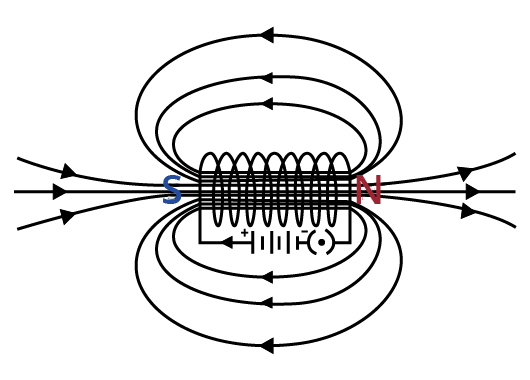
When the north pole of a bar magnet is brought close to the end connected to the negative terminal of the battery, the solenoid repels the bar magnet.
Since we know that like poles repel, we could conclude that they are like poles, that is, the end connected to the -ve end is the north pole. Therefore, the positive end of the solenoid would be the south pole.
9. When is the force experienced by a current-carrying conductor placed in a magnetic field largest?
Ans: The force experienced is found to be maximum when the direction of the current is perpendicular to the direction of the magnetic field.
10. Imagine that you are sitting in a chamber with your back to one wall. An electron beam, moving horizontally from the back wall towards the front wall, is deflected by a strong magnetic field to your right side. What is the direction of magnetic field?
Ans: The direction of the magnetic field could be given by Fleming’s left-hand rule. Magnetic field inside the chamber would be perpendicular to the direction of current (opposite to the direction of electron) and direction of deflection/force i.e., either upward or downward. The direction of current is from the front wall to the back wall as the negatively charged electrons are moving from the back wall to the front wall. Also, the direction of magnetic force is rightward.
Now, by using Fleming’s left-hand rule, it could be concluded that the direction of the magnetic field inside the chamber is downward.
11. Draw a labelled diagram of an electric motor. Explain its principle and working. What is the function of a split ring in an electric motor?
Ans: An electric motor is known to convert electrical energy into mechanical energy. It works based on the principle of the magnetic effect of current. We know that a current-carrying coil rotates in a magnetic field. The following figure shows a simple electric motor.
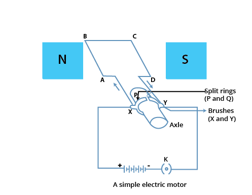
Initially, current is allowed to flow through the coil ABCD by closing the switch. Current in the length AB will flow from A to B and the magnetic field acts from left to right, normal to length AB. Hence, according to Fleming’s left-hand rule, a downward force would act along the length AB and at the same time, an upward force acts along the length CD. As a result, the coil would rotate anti-clockwise.
After half a rotation, the position of AB and CD can be interchanged. The half-ring P comes in contact with brush X and half-ring Q comes in contact with brush Y. Hence, the direction of current in the coil ABCD gets reversed.
The current flows through the coil in the direction DCBA. The reversal of current through the coil ABCD repeats after each half rotation. As a result, the coil rotates unidirectional. The split rings help to reverse the direction of current in the circuit. These are called the commutators.
12. Name some devices in which electric motors are used.
Ans: Water pumps, electric fans, electric mixers and washing machines are some of the devices in which electric motors are used.
13. A coil of insulated copper wire is connected to a galvanometer. What will happen if a bar magnet is:
a. Pushed into the coil?
Ans: If a bar magnet is moved relative to a solenoid, a current would be induced in it. This is known to be the principle of electromagnetic induction.
When a bar magnet is pushed towards a coil of insulated copper wire, a current would be induced momentarily in the coil. As a consequence, the galvanometer’s needle would momentarily deflect in a particular direction.
b. Withdrawn from inside the coil?
Ans: When the bar magnet is withdrawn from inside the coil of insulated copper wire, a current would be again induced momentarily in the coil in the opposite direction. As a result, the galvanometer’s needle would momentarily deflect in the opposite direction.
c. held stationary inside the coil?
Ans: When a bar magnet is held stationary inside the coil, no current can be induced in the coil. Therefore, the galvanometer would not show any deflection.
14. Two circular coils A and B are placed close to each other. If the current in the coil A is changed, will some current be induced in the coil B? Give reason.
Ans: Let two circular coils A and B be placed close to each other. When the current in coil A is changed, the magnetic field associated with it will also change. As a result of this, the magnetic field around coil B would also change. This change in magnetic field lines around coil B would also induce an electric current in it. This is called electromagnetic induction.
15. State the rule to determine the direction of a
a. Magnetic field produced around a straight conductor-carrying current.
Ans: Maxwell’s right-hand thumb rule.
b. Force experienced by a current-carrying straight conductor placed in a magnetic field which is perpendicular to it.
Ans: Fleming’s left-hand rule.
c. Current induced in a coil due to its rotation in a magnetic field.
Ans: Fleming’s right-hand rule.
16. Explain the underlying principle and working of an electric generator by drawing a labelled diagram. What is the function of brushes?
Ans: An electric generator is known to convert mechanical energy into electrical energy. The following figure shows an electric generator:
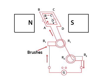
It includes a rotating rectangular coil ABCD that is placed between the two poles of a permanent magnet. The ends of this coil are connected to the two rings ${{R}_{1}}$and ${{R}_{2}}$whose inner sides are insulated. The two conducting stationary brushes ${{B}_{1}}$and ${{B}_{2}}$ are kept pressed separately on the rings ${{R}_{1}}$ and ${{R}_{2}}$.
These rings are also internally attached to an axle. The axle could be mechanically rotated from outside to the coil inside the magnetic field. Outer ends of these brushes are also connected to the galvanometer to show the flow of current into the external circuit. When the axle connected to the two rings is rotated, the arm AB moves up in the magnetic field that is produced by the permanent magnet.
Suppose the coil ABCD is rotated clockwise, on applying Fleming’s right-hand rule, the induced currents are generated in these arms along the directions AB and CD. Hence, an induced current would flow along the direction ABCD. If there are large numbers of turns in the coil, the current that is produced in each turn would add up to give a large current through the coil which means the current flows from ${{B}_{2}}$to ${{B}_{1}}$.
After the half rotation, arm CD would move up and AB would move down. Due to this, the directions of the induced currents in both the arms would change, which in-turn increases the net induced current along the direction DCBA. Now, the current in the external circuit would flow from ${{B}_{1}}$ to ${{B}_{2}}$.
Therefore, after each rotation the polarity of the current in the respective arm would change. Such a current that changes direction after equal intervals of time could be called an alternating current and this device is called an AC generator.
In order to get a direct current, a split-ring type commutator can be used. With this arrangement, one brush at all times in contact with the arm moves up, while the other would move down. Therefore, a unidirectional current would be generated. Hence, the generator could be called a DC generator.
17. When does an electric short circuit occur?
Ans: An electric short circuit is known to occur when:
a. When the resistance of an electric circuit becomes very low and the current that is flowing through the circuit becomes very high. This is caused by connecting too many devices to a single socket or connecting high power rating appliances to the light circuits.
b. When the insulation of live and neutral wires undergoes wear and tear and then they touch each other, the current flowing in the circuit would increase abruptly.
18. What is the function of an earth wire? Why is it necessary to earth metallic appliances?
Ans: Using an earth wire, the metallic body of electric appliances could be connected to the earth so that any electric current leakage is transferred to the ground. This would prevent any electric shock to the user. Therefore, earthing of electrical appliances is very necessary.
Topics Covered in Class 10 Science Chapter 12 - Magnetic Effects of Electric Current
Benefits of NCERT Solutions for Class 10 Science Chapter 12 Magnetic Effects of Electric Current
All class 10 science ch 12 NCERT solutions are per the revised CBSE Term II syllabus and guidelines, ensuring free access.
Class 10 magnetic effects of electric current solutions are prepared by subject matter experts, who help students learn about the concepts easily.
Magnetic effects of electric current class 10 emphasise that electricity and magnetic effect or magnetism are related, providing accurate answers to the questions.
In class 10, magnetic effects of electric current solutions, students will learn about the magnetic field as a quantity with magnitude and directional properties to clarify doubts.
Magnetic effects of electric current question answers are available in chapter-wise PDFs.
Magnetic effects of electric current NCERT solutions are easily accessible both online and offline.
Class 10 science chapter 12 question answers can be downloaded from the website.
Magnetic effects of electric current class 10 NCERT solutions available for zero charges.
Important Study Materials for Class 10 Science Chapter 12
Conclusion
Ch 12 science class 10 NCERT solutions by Vedantu are designed with the main aim of helping students focus on the chapter's important concepts. Every question answer is explained briefly and in an easy-to-understand language to help students improve their conceptual knowledge. The magnetic effects of electric current class 10 questions and answers also contain various shortcut techniques that can be used to remember the concepts effectively. Students can refer to the solutions after reading the complete chapter to improve their understanding.
Other Chapter-wise NCERT Solutions Class 10 Science
You can also access chapter-wise NCERT Solutions for Class 10 Science from the links below and kick-start your preparation for Class 10 Board exams.
Related Links for Class 10 Science


FAQs on NCERT Solutions For Class 10 Science Chapter 12 Magnetic Effects Of Electric Current - 2026-27
1. What is the magnetic effect of electric current?
When electric current flows through a conductor, it produces a magnetic field around it. This phenomenon is called the magnetic effect of electric current. It forms the working principle for devices like electric motors, generators, and electromagnets.
2. Where can I find Class 10 Science Chapter 12 question answers?
Vedantu provides expert-verified NCERT Solutions for Class 10 Science Chapter 12. These solutions cover all in-text and exercise questions, helping students understand concepts accurately and prepare for exams. The answers align with the latest CBSE guidelines.
3. What is Fleming's left-hand rule used for?
Fleming's left-hand rule is used to determine the direction of force experienced by a current-carrying conductor in a magnetic field. It is crucial for understanding the working of an electric motor. The thumb indicates force, the forefinger indicates field, and the middle finger indicates current.
4. Can I download the Magnetic Effects of Electric Current Class 10 NCERT PDF?
Yes, you can download a Free PDF of the NCERT Solutions for this chapter. This allows for easy offline access to all solved questions, diagrams, and step-by-step explanations, making revision convenient before exams.
5. What is electromagnetic induction?
Electromagnetic induction is the process of generating an electric current in a conductor by changing the magnetic field around it. This principle, discovered by Michael Faraday, is the basis for the functioning of electric generators and transformers.
6. How do NCERT solutions for this chapter help in exam preparation?
NCERT Solutions provide clear, step-by-step answers that clarify complex topics like motors and generators. They help students understand the correct format for answering questions, manage time effectively, and revise key concepts to score well in exams.
7. What is the function of an electric motor?
An electric motor is a device that converts electrical energy into mechanical energy. It works on the principle that a current-carrying conductor placed in a magnetic field experiences a force, which causes rotation. Motors are used in fans, washing machines, and refrigerators.
8. What is included in the NCERT Solution for Class 10 Science Chapter 12?
The solutions include detailed answers for all in-text and end-of-chapter exercise questions. They explain concepts like magnetic field lines, solenoids, and domestic electric circuits with diagrams, ensuring a thorough understanding as per the NCERT textbook.
9. What is the difference between overloading and short-circuiting?
Overloading occurs when too many appliances draw excessive current from a single circuit. Short-circuiting happens when the live and neutral wires come into direct contact. Both can cause overheating and potential fires, which are prevented by fuses or MCBs.
10. How can the Magnetic Effects of Electric Current Class 10 NCERT Solutions PDF help with homework?
The NCERT Solutions PDF from Vedantu serves as a reliable reference for completing homework assignments. It offers accurate, structured answers that help students verify their own work, understand the methodology, and clear doubts independently.
11. What is a solenoid and where is it used?
A solenoid is a coil of many circular turns of insulated copper wire wrapped in the shape of a cylinder. When current flows through it, it behaves like a bar magnet. Solenoids are used to make electromagnets for devices like electric bells and circuit breakers.