




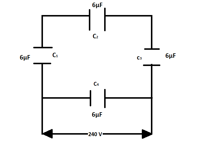
A network of four capacitors of 6μF each is connected to a 240V supply. Determine the charge on each capacitor.
Answer
 Verified
292.5k+ views
Hint: A capacitor is a device used to store an electric charge, consisting of one or more pairs of conductors separated by an insulator.
Capacitors can be added to an electrical circuit either in parallel connection or series connection in both cases the equivalent resistance is calculated in the OPPOSITE way as it is calculated for resistance in series or resistance in parallel.
Complete step by step solution:
Here the capacitors are arranged in a square formation
Or in other words, we can see that capacitors ${C_1},{C_2},{C_3}$ are in series connection and their equivalent conductance will be in parallel connection with capacitor c4
Here this setup is provided a 240 v across it
Now, if capacitors are connected in series connection their equivalent conductance will be given by
\[\dfrac{1}{{C`}} = \dfrac{1}{{{C_1}}} + \dfrac{1}{{{C_2}}} + \dfrac{1}{{{C_3}}}\]
Here in this case capacitors ${C_1},{C_2},{C_3}$ are connected in series connection so their equivalent resistance will be
\[
\dfrac{1}{{C`}} = \dfrac{1}{6} + \dfrac{1}{6} + \dfrac{1}{6} \\
\Rightarrow \dfrac{1}{{C`}} = \dfrac{3}{6} \\
\Rightarrow \dfrac{1}{{C`}} = \dfrac{1}{2} \\
\Rightarrow C` = 2\mu F \\
\]
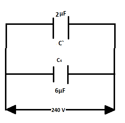
Now our circuit diagram looks like
Now as we can see that the equivalent capacitance $C`$and capacitor ${C_4}$are in parallel connection
If two capacitors are in parallel connection their equivalent capacitance is given by
$C`` = {C_1} + {C_2}$
In this case, the equivalent capacitance will be
$
C`` = C` + {C_4} \\
\therefore C`` = 2 + 6 \\
\Rightarrow C`` = 8\mu F \\
$
So, the total equivalent capacitance of the circuit is $8\mu F$
Now, the amount of charge flowing in the circuit is given by
$q = CV$
Where
$q$ is the charge flowing in the circuit
$C$ is the equivalent capacitance
$V$ is the voltage applied
So the amount of charge flowing across capacitors ${C_1},{C_2},{C_3}$ which are connected in series will be
Given values,
$C = 2\mu F$
Since here capacitance is given in micro Farad we need to convert it into Farad
$
\because 1\mu F = {10^{ - 6}}F \\
\therefore 1\mu F = 2 \times {10^{ - 6}}F \\
$
So,
$ \because q = CV$
$\therefore q = 2 \times {10^{ - 6}} \times 240$
$\Rightarrow q = 4.8 \times {10^{ - 4}}C$
This charge will be flowing across each of the capacitors ${C_1},{C_2},{C_3}$which are in series
Now across capacitor ${C_4}$
Again
$\because q = CV$
$\therefore q = 6 \times {10^{ - 6}} \times 240$
$\Rightarrow q = 1.44 \times {10^{ - 3}}C$
So $1.44 \times {10^{ - 3}}C$ will be the charge flowing across ${C_4}$
The charge flowing across capacitors ${C_1},{C_2},{C_3}$will be $4.8 \times {10^{ - 4}}C$ and the charge flowing across the capacitor ${C_4}$ will be $1.44 \times {10^{ - 3}}C$.
Note: The charge flowing will be divided into two streams one stream will be flowing through capacitors ${C_1},{C_2},{C_3}$ and the other will be flowing across capacitors ${C_4}$ this is the reason why there is a difference between the charges flowing through these capacitors.
Capacitors act as the charge storing devices, in alternating current the store the charge and maintain a positive cycle for AC. Thus saves the change of polarity and helps in the functioning of the electric motors.
Capacitors can be added to an electrical circuit either in parallel connection or series connection in both cases the equivalent resistance is calculated in the OPPOSITE way as it is calculated for resistance in series or resistance in parallel.
Complete step by step solution:
Here the capacitors are arranged in a square formation
Or in other words, we can see that capacitors ${C_1},{C_2},{C_3}$ are in series connection and their equivalent conductance will be in parallel connection with capacitor c4
Here this setup is provided a 240 v across it
Now, if capacitors are connected in series connection their equivalent conductance will be given by
\[\dfrac{1}{{C`}} = \dfrac{1}{{{C_1}}} + \dfrac{1}{{{C_2}}} + \dfrac{1}{{{C_3}}}\]
Here in this case capacitors ${C_1},{C_2},{C_3}$ are connected in series connection so their equivalent resistance will be
\[
\dfrac{1}{{C`}} = \dfrac{1}{6} + \dfrac{1}{6} + \dfrac{1}{6} \\
\Rightarrow \dfrac{1}{{C`}} = \dfrac{3}{6} \\
\Rightarrow \dfrac{1}{{C`}} = \dfrac{1}{2} \\
\Rightarrow C` = 2\mu F \\
\]
Now our circuit diagram looks like
Now as we can see that the equivalent capacitance $C`$and capacitor ${C_4}$are in parallel connection
If two capacitors are in parallel connection their equivalent capacitance is given by
$C`` = {C_1} + {C_2}$
In this case, the equivalent capacitance will be
$
C`` = C` + {C_4} \\
\therefore C`` = 2 + 6 \\
\Rightarrow C`` = 8\mu F \\
$
So, the total equivalent capacitance of the circuit is $8\mu F$
Now, the amount of charge flowing in the circuit is given by
$q = CV$
Where
$q$ is the charge flowing in the circuit
$C$ is the equivalent capacitance
$V$ is the voltage applied
So the amount of charge flowing across capacitors ${C_1},{C_2},{C_3}$ which are connected in series will be
Given values,
$C = 2\mu F$
Since here capacitance is given in micro Farad we need to convert it into Farad
$
\because 1\mu F = {10^{ - 6}}F \\
\therefore 1\mu F = 2 \times {10^{ - 6}}F \\
$
So,
$ \because q = CV$
$\therefore q = 2 \times {10^{ - 6}} \times 240$
$\Rightarrow q = 4.8 \times {10^{ - 4}}C$
This charge will be flowing across each of the capacitors ${C_1},{C_2},{C_3}$which are in series
Now across capacitor ${C_4}$
Again
$\because q = CV$
$\therefore q = 6 \times {10^{ - 6}} \times 240$
$\Rightarrow q = 1.44 \times {10^{ - 3}}C$
So $1.44 \times {10^{ - 3}}C$ will be the charge flowing across ${C_4}$
The charge flowing across capacitors ${C_1},{C_2},{C_3}$will be $4.8 \times {10^{ - 4}}C$ and the charge flowing across the capacitor ${C_4}$ will be $1.44 \times {10^{ - 3}}C$.
Note: The charge flowing will be divided into two streams one stream will be flowing through capacitors ${C_1},{C_2},{C_3}$ and the other will be flowing across capacitors ${C_4}$ this is the reason why there is a difference between the charges flowing through these capacitors.
Capacitors act as the charge storing devices, in alternating current the store the charge and maintain a positive cycle for AC. Thus saves the change of polarity and helps in the functioning of the electric motors.
Recently Updated Pages
JEE Main 2025-26 Electrostatics Mock Test: Free Practice Online

Electrostatics Mock Test 2025: Practice Questions & Answers
JEE Main 2026-27 Kinematics Mock Test – Free Practice Online
JEE Main Mock Test 2025-26: Chapter-Wise Practice Papers
Wheatstone Bridge – Principle, Formula, Diagram & Applications
Kinematics Mock Test 2025: Free Practice Questions & Answers
Trending doubts
JEE Main 2026: Exam Dates, Session 2 Updates, City Slip, Admit Card & Latest News
Understanding the Electric Field of a Uniformly Charged Ring
Understanding Atomic Structure for Beginners
Electron Gain Enthalpy and Electron Affinity Explained
Derivation of Equation of Trajectory Explained for Students
How to Convert a Galvanometer into an Ammeter or Voltmeter
Other Pages
CBSE Class 12 Physics Question Paper 2026: Download SET-wise PDF with Answer Key & Analysis
JEE Advanced Percentile vs Marks 2026: JEE Main Cutoff, AIR & IIT Admission Guide
JEE Advanced 2026 Notification Out with Exam Date, Registration (Extended), Syllabus and More
JEE Advanced Weightage Chapter Wise 2026 for Physics, Chemistry, and Mathematics
Understanding Uniform Acceleration in Physics
What Are Current and Potential Difference in Electricity?