


How do you verify the superposition theorem?
Answer
233.1k+ views
Hint:It is crucial to understand what the superposition theorem is before moving on to the issue. A circuit having several voltage and current sources is equal to the sum of simplified circuits employing just one of the sources, according to the superposition theorem.
Complete step by step solution:
Verification of superposition theorem:
The following experiment can be used to practically validate the superposition theorem.
Circuit diagram:
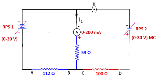
IMAGE: CIRCUIT 1
circuit 2:
circuit 3:
Procedure
1. As seen in the above diagram, connect the circuit.
2. As in circuit 1, set RPS1 and RPS2 to a specific voltage and record the ammeter reading.
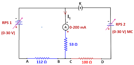
3. Set the voltage to the same level by using RPS1 alone to short RPS2, and then record the ammeter reading as in circuit 2.
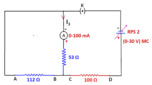
4. As demonstrated in circuit 3, set the same voltage by shorting RPS1 with RPS2 and recording the ammeter measurement.
5. The superposition theorem must be proven.
Verification
Theoretical values
\[{I_1} = {I_2} + {I_3}\] = 140
Practical values
\[{I_1} = {I_2} + {I_3}\] = 90 mA+ 50 mA = 140 mA
Superposition theorem is therefore practically and theoretically verified.
Note :To apply the superposition theorem to circuit currents and voltages, all of the components must be linear. It should be emphasised that since power is not a linear number, the superposition theorem does not apply to it.
Complete step by step solution:
Verification of superposition theorem:
The following experiment can be used to practically validate the superposition theorem.
Circuit diagram:
IMAGE: CIRCUIT 1
circuit 2:
circuit 3:
Procedure
1. As seen in the above diagram, connect the circuit.
2. As in circuit 1, set RPS1 and RPS2 to a specific voltage and record the ammeter reading.
3. Set the voltage to the same level by using RPS1 alone to short RPS2, and then record the ammeter reading as in circuit 2.
4. As demonstrated in circuit 3, set the same voltage by shorting RPS1 with RPS2 and recording the ammeter measurement.
5. The superposition theorem must be proven.
Verification
Theoretical values
| RPS | Ammeter Reading | ||
| 1 | 2 | ||
| Circuit 1 | 20 V | 10 V | \[{I_1} = 140\] |
| Circuit 2 | 20 V | 0 V | \[{I_2} = 90\] |
| Circuit 3 | 0 V | 10 V | \[{I_3} = 50\] |
\[{I_1} = {I_2} + {I_3}\] = 140
Practical values
| RPS | Ammeter reading | ||
| 1 | 2 | ||
| Circuit 1 | 20 V | 10 V | \[{I_1} = 140\] |
| Circuit 2 | 20 V | 0 V | \[{I_2} = 90\] |
| Circuit 3 | 0 V | 10 V | \[{I_3} = 50\] |
\[{I_1} = {I_2} + {I_3}\] = 90 mA+ 50 mA = 140 mA
Superposition theorem is therefore practically and theoretically verified.
Note :To apply the superposition theorem to circuit currents and voltages, all of the components must be linear. It should be emphasised that since power is not a linear number, the superposition theorem does not apply to it.
Recently Updated Pages
JEE Main 2023 April 6 Shift 1 Question Paper with Answer Key
JEE Main 2023 April 6 Shift 2 Question Paper with Answer Key
JEE Main 2023 (January 31 Evening Shift) Question Paper with Solutions [PDF]
JEE Main 2023 January 30 Shift 2 Question Paper with Answer Key
JEE Main 2023 January 25 Shift 1 Question Paper with Answer Key
JEE Main 2023 January 24 Shift 2 Question Paper with Answer Key
Trending doubts
JEE Main 2026: Session 2 Registration Open, City Intimation Slip, Exam Dates, Syllabus & Eligibility
JEE Main 2026 Application Login: Direct Link, Registration, Form Fill, and Steps
Understanding the Angle of Deviation in a Prism
Hybridisation in Chemistry – Concept, Types & Applications
How to Convert a Galvanometer into an Ammeter or Voltmeter
Understanding Uniform Acceleration in Physics
Other Pages
JEE Advanced Marks vs Ranks 2025: Understanding Category-wise Qualifying Marks and Previous Year Cut-offs
Dual Nature of Radiation and Matter Class 12 Physics Chapter 11 CBSE Notes - 2025-26
Understanding the Electric Field of a Uniformly Charged Ring
JEE Advanced Weightage 2025 Chapter-Wise for Physics, Maths and Chemistry
Derivation of Equation of Trajectory Explained for Students
Understanding Electromagnetic Waves and Their Importance