


The phase relationship between current and voltage in a pure resistive circuit is best represented by.
A. 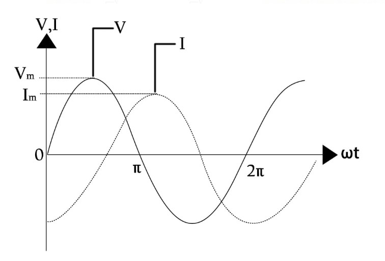
B. 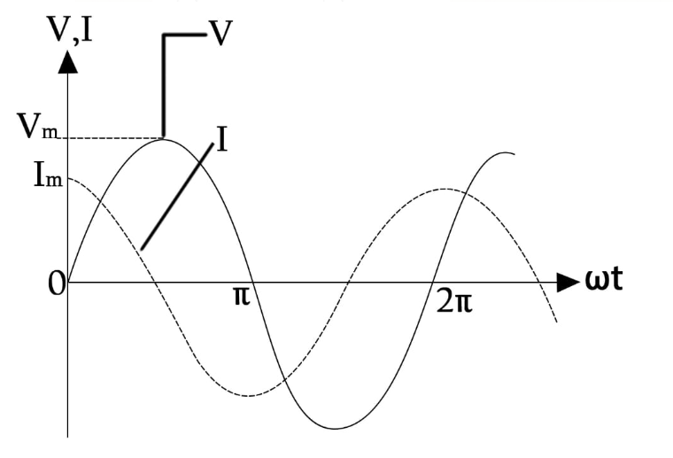
C. 
D . 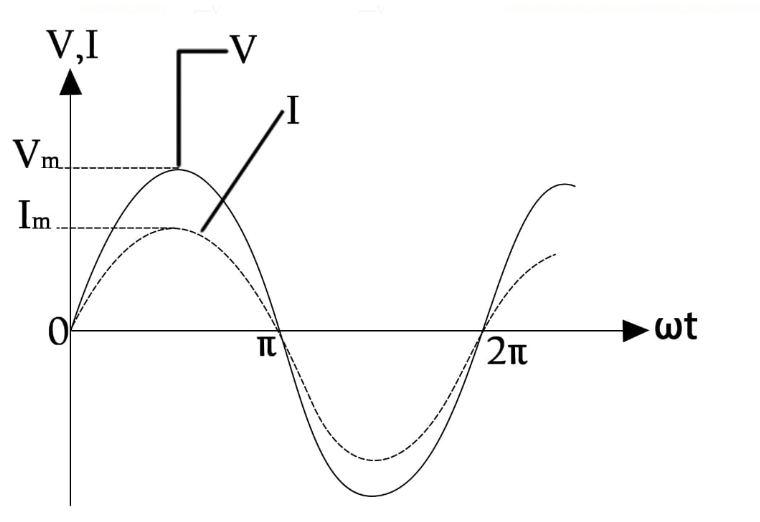
Answer
232.8k+ views
Hint: A pure resistive circuit consists of an AC source and a resistor. There is no phase difference between voltage and current and the current and voltage is said to be in-phase.
Complete step by step answer:
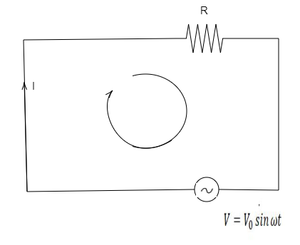
It is given that the circuit is pure resistive which means that there is a resistor in the circuit along with an AC source.
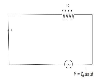
Here ${\text{I}}$ is the current through the circuit and AC source has ${{\text{V}}_{\text{0}}}$ is the voltage difference and ${\text{R}}$ is resistance of the circuit.
Apply Kirchhoff’s law in the given circuit.
Appling Kirchhoff’s law,
$
{V_0}\sin \omega t - I \cdot R = 0 \\
I = \left( {\dfrac{{{V_0}}}{R}} \right)\sin \omega t \\
$
So, here we can see that current in the same phase as of voltage but is less in magnitude then voltage.
The phase diagram in which both voltage and current are in the same phase and also the current is having lesser value than voltage. Let us observe each of the options and see which one is the correct answer for this problem.
In option A the value of current is lesser than that of voltage but there is phase difference in the diagram.
In option B the value of current is lesser than that of voltage but there is a phase difference that is present in the phase diagram.
In option C the value of current is lesser than that of voltage and the phase difference is zero in the phase diagram.
In option D the value of current is lesser than voltage but there is a phase difference in the phase diagram.
Therefore, option C is the correct answer for this problem.
Note: A phase diagram is used to show the relationship between two or more sine waves having the same frequency. While applying Kirchhoff’s rule if we follow the flow of current then we are proceeding from higher potential to the lower potential of the source.
Complete step by step answer:
It is given that the circuit is pure resistive which means that there is a resistor in the circuit along with an AC source.
Here ${\text{I}}$ is the current through the circuit and AC source has ${{\text{V}}_{\text{0}}}$ is the voltage difference and ${\text{R}}$ is resistance of the circuit.
Apply Kirchhoff’s law in the given circuit.
Appling Kirchhoff’s law,
$
{V_0}\sin \omega t - I \cdot R = 0 \\
I = \left( {\dfrac{{{V_0}}}{R}} \right)\sin \omega t \\
$
So, here we can see that current in the same phase as of voltage but is less in magnitude then voltage.
The phase diagram in which both voltage and current are in the same phase and also the current is having lesser value than voltage. Let us observe each of the options and see which one is the correct answer for this problem.
In option A the value of current is lesser than that of voltage but there is phase difference in the diagram.
In option B the value of current is lesser than that of voltage but there is a phase difference that is present in the phase diagram.
In option C the value of current is lesser than that of voltage and the phase difference is zero in the phase diagram.
In option D the value of current is lesser than voltage but there is a phase difference in the phase diagram.
Therefore, option C is the correct answer for this problem.
Note: A phase diagram is used to show the relationship between two or more sine waves having the same frequency. While applying Kirchhoff’s rule if we follow the flow of current then we are proceeding from higher potential to the lower potential of the source.
Recently Updated Pages
JEE Main 2023 April 6 Shift 1 Question Paper with Answer Key
JEE Main 2023 April 6 Shift 2 Question Paper with Answer Key
JEE Main 2023 (January 31 Evening Shift) Question Paper with Solutions [PDF]
JEE Main 2023 January 30 Shift 2 Question Paper with Answer Key
JEE Main 2023 January 25 Shift 1 Question Paper with Answer Key
JEE Main 2023 January 24 Shift 2 Question Paper with Answer Key
Trending doubts
JEE Main 2026: Session 2 Registration Open, City Intimation Slip, Exam Dates, Syllabus & Eligibility
JEE Main 2026 Application Login: Direct Link, Registration, Form Fill, and Steps
JEE Main Marking Scheme 2026- Paper-Wise Marks Distribution and Negative Marking Details
Understanding the Angle of Deviation in a Prism
Hybridisation in Chemistry – Concept, Types & Applications
How to Convert a Galvanometer into an Ammeter or Voltmeter
Other Pages
JEE Advanced Marks vs Ranks 2025: Understanding Category-wise Qualifying Marks and Previous Year Cut-offs
Dual Nature of Radiation and Matter Class 12 Physics Chapter 11 CBSE Notes - 2025-26
Understanding Uniform Acceleration in Physics
Understanding the Electric Field of a Uniformly Charged Ring
JEE Advanced Weightage 2025 Chapter-Wise for Physics, Maths and Chemistry
Derivation of Equation of Trajectory Explained for Students