


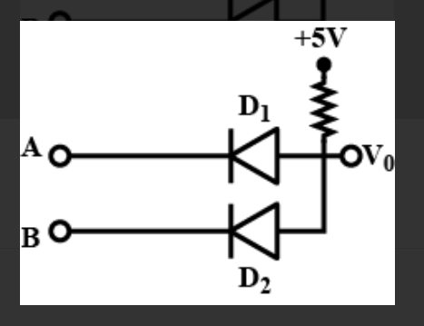
Study the circuit shown in the figure. Name the gate that the given circuit resembles.
(A) NAND
(B) AND
(C) OR
(D NOR
Answer
233.1k+ views
Hint: We know that logic gates perform basic logical functions and are the fundamental building blocks of digital integrated circuits. Most logic gates take an input of two binary values, and output a single value of a 1 or 0. Some circuits may have only a few logic gates, while others, such as microprocessors, may have millions of them. Boolean logic is a very easy way to figure out the truth of an expression using the simple concept of true or false. In a nutshell, Boolean logic means you are working with stuff that is either TRUE or FALSE (and nothing else as Monty Python would say).
Complete step by step answer
We know that Logic gates are the basic building blocks of any digital system. It is an electronic circuit having one or more than one input and only one output. The relationship between the input and the output is based on a certain logic. Based on this, logic gates are named as AND gate, OR gate, NOT gate etc. Digital electronics relies on the actions of just seven types of logic gates, called AND, OR, NAND (Not AND), NOR (Not OR), XOR (Exclusive OR) XNOR (Exclusive NOR) and NOT. Because, in binary logic there are only two states, 1 and 0 or 'on and off,' NOT in the world of binary logic therefore means 'the opposite of'.
The circuit resembles an AND gate. The Boolean expression of this
circuit is $\mathrm{V}_{0}=\mathrm{A.B}$ that is $\mathrm{V}_{0}$ equals A AND B.
The truth table is given below:
So, the correct answer is option B.
Note: We can conclude that the AND gate is so named because, if 0 is called "false" and 1 is called "true," the gate acts in the same way as the logical "and" operator. The output is "true" when both inputs are "true." Otherwise, the output is "false." In other words, the output is 1 only when both inputs one AND two are 1. When a transistor is on, or open, then an electric current can flow through. When we string a bunch of these transistors together, then we get what's called a logic gate, which lets you add, subtract, multiply, and divide binary numbers in any way imaginable. In a physical circuit, these logic gates have: Inputs.
Complete step by step answer
We know that Logic gates are the basic building blocks of any digital system. It is an electronic circuit having one or more than one input and only one output. The relationship between the input and the output is based on a certain logic. Based on this, logic gates are named as AND gate, OR gate, NOT gate etc. Digital electronics relies on the actions of just seven types of logic gates, called AND, OR, NAND (Not AND), NOR (Not OR), XOR (Exclusive OR) XNOR (Exclusive NOR) and NOT. Because, in binary logic there are only two states, 1 and 0 or 'on and off,' NOT in the world of binary logic therefore means 'the opposite of'.
The circuit resembles an AND gate. The Boolean expression of this
circuit is $\mathrm{V}_{0}=\mathrm{A.B}$ that is $\mathrm{V}_{0}$ equals A AND B.
The truth table is given below:
| A | B | Y |
| 0 | 0 | 0 |
| 0 | 1 | 0 |
| 1 | 0 | 0 |
| 1 | 1 | 1 |
So, the correct answer is option B.
Note: We can conclude that the AND gate is so named because, if 0 is called "false" and 1 is called "true," the gate acts in the same way as the logical "and" operator. The output is "true" when both inputs are "true." Otherwise, the output is "false." In other words, the output is 1 only when both inputs one AND two are 1. When a transistor is on, or open, then an electric current can flow through. When we string a bunch of these transistors together, then we get what's called a logic gate, which lets you add, subtract, multiply, and divide binary numbers in any way imaginable. In a physical circuit, these logic gates have: Inputs.
Recently Updated Pages
JEE Main 2023 April 6 Shift 1 Question Paper with Answer Key
JEE Main 2023 April 6 Shift 2 Question Paper with Answer Key
JEE Main 2023 (January 31 Evening Shift) Question Paper with Solutions [PDF]
JEE Main 2023 January 30 Shift 2 Question Paper with Answer Key
JEE Main 2023 January 25 Shift 1 Question Paper with Answer Key
JEE Main 2023 January 24 Shift 2 Question Paper with Answer Key
Trending doubts
JEE Main 2026: Session 2 Registration Open, City Intimation Slip, Exam Dates, Syllabus & Eligibility
JEE Main 2026 Application Login: Direct Link, Registration, Form Fill, and Steps
Understanding the Angle of Deviation in a Prism
Hybridisation in Chemistry – Concept, Types & Applications
How to Convert a Galvanometer into an Ammeter or Voltmeter
Understanding Uniform Acceleration in Physics
Other Pages
JEE Advanced Marks vs Ranks 2025: Understanding Category-wise Qualifying Marks and Previous Year Cut-offs
Dual Nature of Radiation and Matter Class 12 Physics Chapter 11 CBSE Notes - 2025-26
Understanding the Electric Field of a Uniformly Charged Ring
JEE Advanced Weightage 2025 Chapter-Wise for Physics, Maths and Chemistry
Derivation of Equation of Trajectory Explained for Students
Understanding Electromagnetic Waves and Their Importance