


Write the truth table for the circuits given in figure. Considering of NOR gate only. Identify the logic operations (OR, AND, NOT) performed by the two circuits.
Answer
270.6k+ views
Hint: In the above solved question, we have used Boolean operations for some basic logic gates such as OR, AND, NOT gates. We drew truth tables for the combinations of basic logic gates, which represents their functions for all combinations of input signals.
Complete step-by-step answer:
Logic gates are important digital devices that are mainly based on the Boolean functions. Logic gates take one or more binary (0 or 1) input signal, and carry out logical operations on them and give one binary (0 or 1) output.
Boolean operations for several basic gates-
1. For OR gate: $Y = X + Y$
2. For AND gate: $Y = X·Y$.
3. For NOT gate: $Y=\overline{X}$
Now using the above described Boolean functions, we can make truth tables for the figures mentioned in the question.
1. Truth table for diagram (a)-
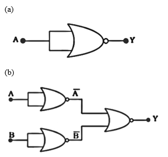
It is a NOR gate, which has both input A and output Y.
So, the operation will be $Y=\overline{A}$.
As, $Y=\overline{X+Y}=\overline{A+A}=\overline{A}$
2. Truth table for diagram (b)-
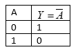
It is a three NOR gates circuit, it’s output will be $Y=\overline{\overline{A}+\overline{B}}$
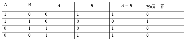
If you observe carefully, this gate essentially is an AND gate.
Note: According to their mode of operations, logic gates have a lot of applications.
Logic gates are usually found in circuits such as safety thermostat, push-button lock, automatic watering system, light activated burglar alarm system.
Logic gates can be found in IC circuits.
Complete step-by-step answer:
Logic gates are important digital devices that are mainly based on the Boolean functions. Logic gates take one or more binary (0 or 1) input signal, and carry out logical operations on them and give one binary (0 or 1) output.
Boolean operations for several basic gates-
1. For OR gate: $Y = X + Y$
2. For AND gate: $Y = X·Y$.
3. For NOT gate: $Y=\overline{X}$
Now using the above described Boolean functions, we can make truth tables for the figures mentioned in the question.
1. Truth table for diagram (a)-
It is a NOR gate, which has both input A and output Y.
So, the operation will be $Y=\overline{A}$.
As, $Y=\overline{X+Y}=\overline{A+A}=\overline{A}$
2. Truth table for diagram (b)-
It is a three NOR gates circuit, it’s output will be $Y=\overline{\overline{A}+\overline{B}}$
If you observe carefully, this gate essentially is an AND gate.
Note: According to their mode of operations, logic gates have a lot of applications.
Logic gates are usually found in circuits such as safety thermostat, push-button lock, automatic watering system, light activated burglar alarm system.
Logic gates can be found in IC circuits.
Recently Updated Pages
JEE General Topics in Chemistry Important Concepts and Tips
JEE Extractive Metallurgy Important Concepts and Tips for Exam Preparation
JEE Atomic Structure and Chemical Bonding important Concepts and Tips
JEE Amino Acids and Peptides Important Concepts and Tips for Exam Preparation
Electricity and Magnetism Explained: Key Concepts & Applications
JEE Energetics Important Concepts and Tips for Exam Preparation
Trending doubts
JEE Main 2026: Exam Dates, Session 2 Updates, City Slip, Admit Card & Latest News
JEE Main Participating Colleges 2026 - A Complete List of Top Colleges
Understanding the Electric Field of a Uniformly Charged Ring
Understanding Atomic Structure for Beginners
Derivation of Equation of Trajectory Explained for Students
JEE Main Marking Scheme 2026- Paper-Wise Marks Distribution and Negative Marking Details
Other Pages
JEE Advanced 2026 Notification Out with Exam Date, Registration (Extended), Syllabus and More
JEE Advanced Percentile vs Marks 2026: JEE Main Cutoff, AIR & IIT Admission Guide
JEE Advanced 2026 Marks vs Rank: Estimate IIT Rank from Your Score
JEE Advanced Weightage Chapter Wise 2026 for Physics, Chemistry, and Mathematics
How to Convert a Galvanometer into an Ammeter or Voltmeter
Electron Gain Enthalpy and Electron Affinity Explained