


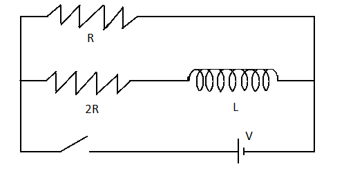
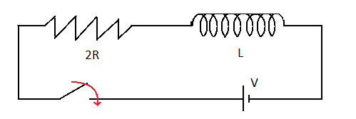
The ratio of time constant in charging and discharging in the circuit shown in figure is:
A) $1:1$
B) $3:2$
C) $2:3$
D) $1:3$
Answer
232.8k+ views
Hint: The circuit consists of an inductor and two resistors. During, charging all the energy supplied to the circuit is stored in the inductor itself. No potential difference across the top resistor will be observed. During discharging the battery is disconnected and the energy is supplied by the inductor.
Complete step by step solution:
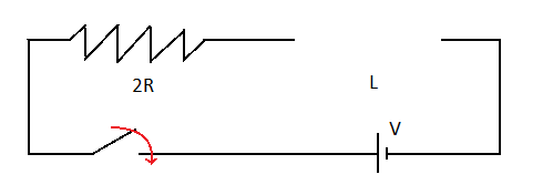
Let us understand the process of charging. An inductor is an electrical component which stores energy in its magnetic field. So, during charging, all the energy supplied to the circuit will be stored in the inductor. This will continue until the inductor is completely charged. During this process there is no flow of current through the resistance $R$ .
Hence, the effective circuit will be as follows:
The red mark indicates that the circuit is closed and electric current is flowing through the circuit. Be careful that the electric current only reaches and the circuit is not complete. More appropriate way of representing the diagram would be:
Now, time constant $$ \Rightarrow \dfrac{{{\tau _1}}}{{{\tau _2}}} = \dfrac{3}{2}$$ where $L$ is the value of inductance and ${R_{eff}}$ indicates the effective resistance.
Since current is flowing only through the $2R$ resistor.
Therefore, the time constant during charging will be: $${\tau _1} = \dfrac{L}{{2R}}$$
Discharging case: In case of discharging the power supply will be removed and the current flowing in the circuit will be due to the energy stored in the inductor. Let’s draw the circuit diagram for the same:
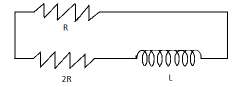
Here, the effective resistance will be $$R + 2R = 3R$$
The time constant will be $${\tau _2} = \dfrac{L}{{3R}}$$
Clearly the ratio for charging and discharging will be
$$\dfrac{{{\tau _1}}}{{{\tau _2}}} = \dfrac{{\dfrac{L}{{2R}}}}{{\dfrac{L}{{3R}}}}$$
$$ \Rightarrow \dfrac{{{\tau _1}}}{{{\tau _2}}} = \dfrac{3}{2}$$
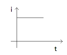
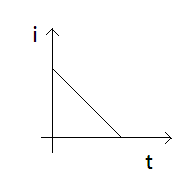
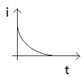
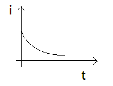
The graph depicts the ratio of current versus time.
Therefore, option B is the correct answer.
Note: Remember that inductor is a passive component, it does not produce energy on its own. Instead it stores energy when electric current flows through the circuit, in a magnetic field. Remember that during discharging the power supply is removed.
Complete step by step solution:
Let us understand the process of charging. An inductor is an electrical component which stores energy in its magnetic field. So, during charging, all the energy supplied to the circuit will be stored in the inductor. This will continue until the inductor is completely charged. During this process there is no flow of current through the resistance $R$ .
Hence, the effective circuit will be as follows:
The red mark indicates that the circuit is closed and electric current is flowing through the circuit. Be careful that the electric current only reaches and the circuit is not complete. More appropriate way of representing the diagram would be:
Now, time constant $$ \Rightarrow \dfrac{{{\tau _1}}}{{{\tau _2}}} = \dfrac{3}{2}$$ where $L$ is the value of inductance and ${R_{eff}}$ indicates the effective resistance.
Since current is flowing only through the $2R$ resistor.
Therefore, the time constant during charging will be: $${\tau _1} = \dfrac{L}{{2R}}$$
Discharging case: In case of discharging the power supply will be removed and the current flowing in the circuit will be due to the energy stored in the inductor. Let’s draw the circuit diagram for the same:
Here, the effective resistance will be $$R + 2R = 3R$$
The time constant will be $${\tau _2} = \dfrac{L}{{3R}}$$
Clearly the ratio for charging and discharging will be
$$\dfrac{{{\tau _1}}}{{{\tau _2}}} = \dfrac{{\dfrac{L}{{2R}}}}{{\dfrac{L}{{3R}}}}$$
$$ \Rightarrow \dfrac{{{\tau _1}}}{{{\tau _2}}} = \dfrac{3}{2}$$
The graph depicts the ratio of current versus time.
Therefore, option B is the correct answer.
Note: Remember that inductor is a passive component, it does not produce energy on its own. Instead it stores energy when electric current flows through the circuit, in a magnetic field. Remember that during discharging the power supply is removed.
Recently Updated Pages
JEE Main 2023 April 6 Shift 1 Question Paper with Answer Key
JEE Main 2023 April 6 Shift 2 Question Paper with Answer Key
JEE Main 2023 (January 31 Evening Shift) Question Paper with Solutions [PDF]
JEE Main 2023 January 30 Shift 2 Question Paper with Answer Key
JEE Main 2023 January 25 Shift 1 Question Paper with Answer Key
JEE Main 2023 January 24 Shift 2 Question Paper with Answer Key
Trending doubts
JEE Main 2026: Session 2 Registration Open, City Intimation Slip, Exam Dates, Syllabus & Eligibility
JEE Main 2026 Application Login: Direct Link, Registration, Form Fill, and Steps
Understanding the Angle of Deviation in a Prism
Hybridisation in Chemistry – Concept, Types & Applications
How to Convert a Galvanometer into an Ammeter or Voltmeter
Understanding Uniform Acceleration in Physics
Other Pages
JEE Advanced Marks vs Ranks 2025: Understanding Category-wise Qualifying Marks and Previous Year Cut-offs
Dual Nature of Radiation and Matter Class 12 Physics Chapter 11 CBSE Notes - 2025-26
Understanding the Electric Field of a Uniformly Charged Ring
JEE Advanced Weightage 2025 Chapter-Wise for Physics, Maths and Chemistry
Derivation of Equation of Trajectory Explained for Students
Understanding Electromagnetic Waves and Their Importance