


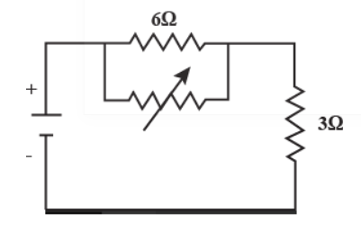
The circuit given below is for the operation of an industrial fan. The resistance of the fan is 3 ohms. The regulator provided with the fan is a fixed resistor and a variable resistor in parallel.
Under what value of the variable resistance given below, Power transferred to the fans will be maximum? The power source of the fan is a de source with internal resistance of 6 ohm.
(A) $3\Omega $
(B) 0
(C) $\infty $
(D) $6\Omega $
Answer
233.1k+ views
Hint: We know that a parallel circuit has two or more paths for current to flow through. Voltage is the same across each component of the parallel circuit. The sum of the currents through each path is equal to the total current that flows from the source. In a series circuit, the sum of the voltages consumed by each individual resistance is equal to the source voltage. Components connected in parallel are connected along multiple paths so that the current can split up; the same voltage is applied to each component.
Complete step by step answer
It can be said that therefore, the condition for maximum power dissipation across the load is \[{{R}_{L}}={{R}_{Th}}\]. That means, if the value of load resistance is equal to the value of source resistance that is Thevenin's resistance, then the power dissipated across the load will be of maximum value.
We can also add that the Maximum Power Transfer Theorem is another useful circuit analysis method to ensure that the maximum amount of power will be dissipated in the load resistance when the value of the load resistance is exactly equal to the resistance of the power source.
We know that the power transferred to fan is given as $\mathrm{P}=\mathrm{V}^{2} / \mathrm{R},$ where $\mathrm{R}$ is the total resistance of the circuit.
As power is inversely proportional to total resistance.
So, for maximum power, the total resistance should be minimum.
Total resistance here is $\text{R}=\dfrac{6\text{r}}{6+\text{r}}+3$
r is the variable resistance.
$\mathrm{R}$ is minimum when $\mathrm{r}=0$.
Hence the correct answer is option B.
Note: We can say that voltage is the same across each component of the parallel circuit. The sum of the currents through each path is equal to the total current that flows from the source. In a series circuit, all components are connected end-to-end, forming a single path for current flow. In a parallel circuit, all components are connected across each other, forming exactly two sets of electrically common points. The main reason parallel circuitry is used in this context is to take advantage of more than one power source, like when more than one battery is being used in a portable device. Using parallel circuits, a device takes an equal amount of power from different sources and combines it on the same line.
Recently Updated Pages
JEE Main 2023 April 6 Shift 1 Question Paper with Answer Key
JEE Main 2023 April 6 Shift 2 Question Paper with Answer Key
JEE Main 2023 (January 31 Evening Shift) Question Paper with Solutions [PDF]
JEE Main 2023 January 30 Shift 2 Question Paper with Answer Key
JEE Main 2023 January 25 Shift 1 Question Paper with Answer Key
JEE Main 2023 January 24 Shift 2 Question Paper with Answer Key
Trending doubts
JEE Main 2026: Session 2 Registration Open, City Intimation Slip, Exam Dates, Syllabus & Eligibility
JEE Main 2026 Application Login: Direct Link, Registration, Form Fill, and Steps
Understanding the Angle of Deviation in a Prism
Hybridisation in Chemistry – Concept, Types & Applications
How to Convert a Galvanometer into an Ammeter or Voltmeter
Understanding Uniform Acceleration in Physics
Other Pages
JEE Advanced Marks vs Ranks 2025: Understanding Category-wise Qualifying Marks and Previous Year Cut-offs
Dual Nature of Radiation and Matter Class 12 Physics Chapter 11 CBSE Notes - 2025-26
Understanding the Electric Field of a Uniformly Charged Ring
JEE Advanced Weightage 2025 Chapter-Wise for Physics, Maths and Chemistry
Derivation of Equation of Trajectory Explained for Students
Understanding Electromagnetic Waves and Their Importance