


How Does Electric Current Flow and What Factors Affect It?
Current electricity refers to the continuous flow of electric charge through a conductor due to a potential difference. This phenomenon underpins the operation of electrical circuits and is fundamental in the study of physics and engineering, especially for applications in modern technology and examinations like JEE Main.
Nature and Definition of Electric Current
Electric current ($I$) is defined as the rate of flow of electric charge ($Q$) through a cross-section of a conductor. It is a scalar quantity with the SI unit ampere (A). The fundamental expression for electric current is $I = \dfrac{Q}{t}$, where $t$ is the time interval in seconds.
The direction of conventional current is taken as the direction a positive charge would move, from higher to lower potential. However, in metallic conductors, it is electrons (negatively charged) that flow in the opposite direction of conventional current.
Types of Current: Direct and Alternating
Current electricity is broadly classified into direct current (DC) and alternating current (AC), based on the direction of flow of charges. DC flows in a single fixed direction, while AC changes direction periodically. Understanding these types is essential in circuit analysis and practical applications.
| Direct Current (DC) | Alternating Current (AC) |
|---|---|
| Flows in one direction only | Direction reverses periodically |
| Produced by batteries and cells | Supplied by power stations |
| Stable voltage output | Voltage varies sinusoidally |
| Used in electronics and chargers | Used in domestic supply and industry |
Electric circuits using DC sources like cells have unidirectional charge motion, whereas AC sources cause cyclic reversal in the movement of charge carriers. This distinction guides their use in devices and power systems.
Current Electricity vs Static Electricity
Unlike static electricity, which involves stationary charges, current electricity deals with moving charges within a closed conducting path. The steady flow of charges constitutes current, whereas static charges result in short-lived phenomena without continuous flow.
| Current Electricity | Static Electricity |
|---|---|
| Charges in motion | Charges at rest |
| Needs closed circuit and voltage | Produced by friction or induction |
| Continuous and steady | Temporary and short-lived |
| Drives electric circuits | Detected by sparks or attraction |
The understanding of differences between current electricity and static electricity is foundational in physics and is frequently examined in competitive assessments.
Fundamental Laws and Formulae of Current Electricity
Key laws govern current electricity and enable calculation of related quantities. Ohm's law is a primary relationship, connecting current ($I$), voltage ($V$), and resistance ($R$) in a conductor using the equation $V = IR$.
The resistance ($R$) of a conductor depends on its material (resistivity $\rho$), length ($l$), and cross-sectional area ($A$), described as $R = \rho \dfrac{l}{A}$. Power ($P$) dissipated in a conductor is given by $P = VI = I^2R = \dfrac{V^2}{R}$.
These formulae are crucial in calculations involving electric circuits, especially for problem-solving in exams and practical engineering. For detailed exploration of resistance concepts, refer to Electrical Resistance.
Microscopic Origin: Drift Velocity
The flow of current in metallic conductors results from the drift of free electrons under an applied electric field. The average velocity attained by these electrons, known as drift velocity ($v_d$), links microscopic motion to macroscopic current.
The relation is $I = nAe v_d$, where $n$ is the number of free electrons per unit volume, $A$ is the cross-sectional area, $e$ is the elementary charge, and $v_d$ is the drift velocity. This expression connects material properties to observable current.
Effects of Electric Current
When electric current passes through a conductor, it produces observable effects such as the magnetic, chemical, and heating effects. Each effect is applied extensively in technology and laboratory setups.
- Magnetic field generation around conductors
- Heating due to resistance in the pathway
- Chemical changes during electrolysis processes
The Joule’s law of heating quantifies the heat produced by a current, given by $H = I^2Rt$, where $H$ is heat in joules, $I$ is the current, $R$ is the resistance, and $t$ is time in seconds.
Current’s magnetic effect forms the basis of electromagnets, motors, and transformers, while the chemical effect appears in electroplating and electrolytic cells. Understanding these effects is essential in both theoretical and practical domains.
Analyzing Circuits: Series and Parallel Connections
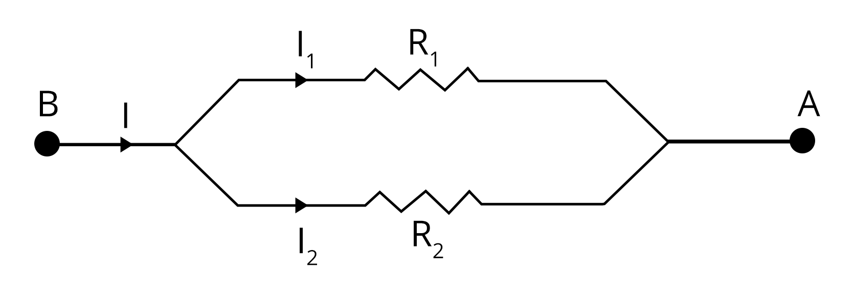
Electric circuits may contain resistors connected in series or parallel. For series connection, total resistance is additive: $R_\text{eq} = R_1 + R_2 + \dots$. For parallel connection, the reciprocal law applies: $\dfrac{1}{R_\text{eq}} = \dfrac{1}{R_1} + \dfrac{1}{R_2} + \dots$
Solving such networks requires the proper application of Ohm’s law and equivalent resistance formulae. Circuit problem-solving is further detailed in Circuit Solving.
Sample Problems in Current Electricity
Solving numerical problems strengthens conceptual understanding. Sample calculations using the above relations are crucial for JEE Main preparation and practical applications.
- Find the current ($I$) when $Q=1200\,\text{C}$ flows in $4\,\text{min}$: $I = \dfrac{Q}{t} = \dfrac{1200}{240} = 5\,\text{A}$.
- If a $8\,\Omega$ resistor carries a current of $3\,\text{A}$, the voltage is $V = IR = 3 \times 8 = 24\,\text{V}$.
- For resistors of $4\,\Omega$ and $12\,\Omega$ in parallel, $R_\text{eq} = \dfrac{1}{\dfrac{1}{4} + \dfrac{1}{12}} = 3\,\Omega$.
Mastery in solving such problems improves accuracy and confidence in examination settings. Practice is essential for developing speed and reliability in current electricity questions. For practice, use the Current Electricity Mock Test.
Applications of Current Electricity
Current electricity enables the functioning of devices such as lights, computers, medical equipment, transformers, and motors. It is central to power transmission and modern electronics. Technological progress relies on controlled flow of current in various circuit configurations.
- Household lighting and heating systems
- Electric trains and transportation
- Computers and communication devices
- Electrolysis and chemical processing
Advanced devices like RL circuits and precision measuring instruments utilize principles of current electricity. Study more about RL circuit applications at RL Circuit.
Units and Measurement in Current Electricity
The ampere (A) is the SI unit of electric current. Electric charge is measured in coulombs (C), potential difference in volts (V), and resistance in ohms (Ω). Accurate measurement using ammeters, voltmeters, and other devices is necessary for circuit analysis.
| Quantity | SI Unit |
|---|---|
| Electric Current ($I$) | Ampere (A) |
| Electric Charge ($Q$) | Coulomb (C) |
| Potential Difference ($V$) | Volt (V) |
| Resistance ($R$) | Ohm (Ω) |
Precision in unit usage and measurement techniques is crucial in performing correct calculations and interpreting experimental results. Related concepts such as EMF and internal resistance are further explained at EMF and Internal Resistance of a Cell.
Key Points for Mastery in JEE Main
To excel in current electricity, it is essential to remember core formulae, understand differences between circuit types, and develop proficiency in applying laws to analyze electrical networks. Consistent practice with JEE-type problems ensures conceptual clarity and problem-solving speed.
- Memorize $I = Q/t$, $V = IR$, $P = I^2R$
- Distinguish between AC and DC behavior
- Apply correct methods for series and parallel
- Use SI units consistently in calculations
- Refer to standard sign conventions in circuits
More resources for strengthening concepts in resistance and Ohm’s law can be found at Ohm's Law and Resistance.
FAQs on Understanding Current Electricity: Concepts, Formulas, and Uses
1. What is current electricity in physics?
Current electricity refers to the flow of electric charge, usually carried by electrons, through a conductor such as a wire. This flow forms the basis of most practical electrical circuits and devices. Key facts include:
- Current electricity is different from static electricity, as it involves continuous movement of charge.
- It requires a closed electric circuit for the flow of charges.
- The unit of current is ampere (A).
2. State Ohm's Law and its mathematical expression.
Ohm's Law states that the electric current passing through a conductor is directly proportional to the potential difference across its ends, provided the temperature remains constant. It is fundamental to understanding current electricity. The mathematical expression is:
- V = I × R
- Where V = potential difference (voltage), I = current, and R = resistance.
3. What are the factors affecting the resistance of a conductor?
Resistance of a conductor depends on several physical factors. These include:
- Length (l) – resistance increases with length.
- Area of cross-section (A) – resistance decreases as area increases.
- Nature of material – certain materials offer higher/lower resistance.
- Temperature – resistance usually increases with temperature for metals.
4. What is the difference between electric potential and electric current?
Electric potential refers to the amount of electric potential energy per unit charge at a point, while electric current is the rate of flow of electric charge. Key differences:
- Potential is measured in volts (V); current in amperes (A).
- Potential causes current if a circuit is closed.
5. Explain the concept of electric circuit and its types.
An electric circuit is a closed path in which electric current flows. Types include:
- Series circuit: Components are connected end-to-end; current is the same through all components.
- Parallel circuit: Components are connected across the same voltage; total current is the sum of individual branch currents.
6. What is a resistor and what are its uses?
A resistor is an electrical component that restricts or limits the flow of electric current in a circuit. Its main uses include:
- Controlling current in electronic circuits
- Voltage division
- Protection of devices from excessive current
- Generating heat (e.g., in electric heaters)
7. Define electric power and write its formula.
Electric power is the rate at which electrical energy is transferred by a circuit. The basic formula is:
- P = V × I, where P is power in watts, V is voltage, and I is current.
- Alternative forms: P = I²R or P = V²/R
8. How do conductors and insulators differ in terms of current electricity?
Conductors allow electric current to flow easily, while insulators resist current flow. Key points:
- Conductors have low resistance; examples: copper, aluminium.
- Insulators have high resistance; examples: rubber, glass.
- This difference is essential for safe handling of electric circuits.
9. What are the safety precautions to be taken while working with electric circuits?
It is important to follow safety measures when dealing with current electricity to avoid hazards. Some precautions are:
- Always use dry hands and wear insulating footwear.
- Switch off the power supply before touching or repairing circuits.
- Avoid overloading circuits and use fuses/circuit breakers.
- Do not touch live wires with bare hands.
10. What are the applications of current electricity in daily life?
Current electricity is essential for modern life and is used in multiple applications, such as:
- Lighting (bulbs, LEDs)
- Household appliances (fans, refrigerators)
- Electronic devices (computers, mobiles)
- Industrial equipment and machines
- Transportation (electric trains, e-vehicles)
11. What is meant by electric charge flow in metals?
Electric charge flow in metals refers to the movement of free electrons within the metal lattice. When a potential difference is applied, these electrons drift from negative to positive, resulting in current electricity.
12. State the SI unit of electric current and how is it defined?
The SI unit of electric current is the ampere (A). It is defined as the flow of one coulomb of charge per second through a conductor.