


How to Calculate Self Inductance of a Solenoid with Examples
Self inductance is a crucial property of solenoids that affects how they respond to changing currents. It describes the ability of a solenoid to induce an emf in itself when the current passing through it varies, a concept vital in understanding many electromagnetic phenomena.
What is Self Inductance in a Solenoid?
When current in a solenoid changes, the magnetic field inside it changes too. This changing field creates an induced emf that opposes the change in current, according to Lenz’s Law. This opposition is quantified as self inductance, denoted by $L$.
A classic real-life analogy is a train's inertia: just as a train resists speed changes, a solenoid resists changing current due to its self inductance.
Mathematically, the induced emf $E$ in a solenoid due to self-inductance is given by $E = -L \dfrac{dI}{dt}$, where $I$ is the current. The negative sign reflects the opposition to current change.
Derivation of the Self Inductance Formula
Consider a long solenoid of length $l$, total turns $N$, and cross-sectional area $A$. Assume it has an air core with magnetic permeability $\mu_0$.
The number of turns per unit length is $n = \dfrac{N}{l}$. The solenoid is assumed tightly wound and much longer than its diameter to ensure a uniform magnetic field inside.
The magnetic field inside a long solenoid is $B = \mu_0 n I = \mu_0 \dfrac{N}{l} I$. Here, $I$ is the current through the solenoid.
The magnetic flux through one turn is: $\Phi = B \times A = \mu_0 \dfrac{N}{l} I \times A$.
So, the total flux linked with all $N$ turns is: $\Phi_{\text{total}} = N\Phi = N(\mu_0 \dfrac{N}{l} I \times A) = \mu_0 \dfrac{N^2 A}{l} I$.
By the definition of self inductance: $\Phi_{\text{total}} = L I$.
Comparing terms, self inductance is: $L = \mu_0 \dfrac{N^2 A}{l}$.
Thus, the self inductance of a solenoid depends on the square of number of turns ($N^2$), cross-sectional area ($A$), and length ($l$), as well as the magnetic permeability of the core.
Key Principles: Direct Proportionality and Dependence
Self inductance of a solenoid is directly proportional to $\mu_0$, $N^2$, and $A$, but inversely proportional to $l$. Any change in these physical parameters influences the solenoid's ability to oppose current change.
Replacing the air core with a material of permeability $\mu = \mu_0 \mu_r$ (relative permeability $\mu_r$), increases self inductance by a factor of $\mu_r$.
Physical Meaning and Unit of Self Inductance in Solenoids
The SI unit of self inductance is henry (H). One henry is the inductance when a current change of one ampere per second induces an emf of one volt.
| Physical Quantity | SI Unit |
|---|---|
| Self Inductance (L) | henry (H) |
| Current (I) | ampere (A) |
| Induced emf (E) | volt (V) |
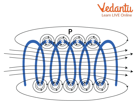
Self Inductance: Solenoid Diagram and Visual Model
A tightly wound coil with labeled turns, area, and core provides a clear model for understanding self-inductance. Such arrangements are the basis for teaching and for engineering applications in circuits.
What Self Inductance of a Solenoid Depends On
The magnitude of self inductance in a solenoid is affected by several physical factors, many of which can be controlled during design or in experiments.
- Increasing the number of turns increases self inductance dramatically.
- Larger cross-sectional area provides more flux linkage potential.
- Shorter solenoids have higher self inductance for the same number of turns.
- Using a magnetic core raises inductance compared to an air core.
Common Misconceptions and Errors
Students often confuse self inductance with resistance, though they are entirely different—one opposes changes in current, while the other opposes the current itself.
A common error is to overlook the dependence on $N^2$. Doubling the turns results in four times the self inductance, not double.
Numerical Example: Calculating Self Inductance of a Solenoid
A solenoid has 400 turns, cross-sectional area $3 \times 10^{-4}\ \rm m^2$, and length $0.5\ \rm m$. Calculate its self inductance.
Given values: $N = 400$, $A = 3 \times 10^{-4}\ \rm m^2$, $l = 0.5\ \rm m$, and $\mu_0 = 4\pi \times 10^{-7}\ \rm H/m$.
The formula for self-inductance is: $L = \mu_0 \dfrac{N^2 A}{l}$.
Substituting values: $L = 4\pi \times 10^{-7} \dfrac{(400)^2 \times 3 \times 10^{-4}}{0.5}$.
$L = 4\pi \times 10^{-7} \dfrac{160000 \times 3 \times 10^{-4}}{0.5}$.
$L = 4\pi \times 10^{-7} \dfrac{48}{0.5}$.
$L = 4\pi \times 10^{-7} \times 96 = 384\pi \times 10^{-7} = 1.21 \times 10^{-4}\ \rm H$.
The final answer is $L \approx 0.12\ \rm mH$. This shows the solenoid’s self inductance when air-cored and tightly wound.
Comparison: Self Inductance vs. Mutual Inductance
| Self Inductance | Mutual Inductance |
|---|---|
| Depends on single coil’s features | Depends on two coils’ orientation |
| Symbol $L$, unit henry (H) | Symbol $M$, unit henry (H) |
| Opposes self current change | Links emf in a second coil |
Real-World Applications of Solenoid Self Inductance
- Used in electrical filters in radio transmitters and receivers
- Found in transformer construction for efficient energy transfer
- Form core components in relays and chokes
- Employed in SMPS and power conversion devices
- Play roles in magnetic sensors and actuation
Sample Practice Question on Self Inductance
If the number of turns in a solenoid is tripled while keeping length and area constant, by what factor does its self inductance change? Explain your reasoning.
Related Physics Topics
- For a broad overview, visit Understanding Inductors.
- For derivations and foundational ideas, see Self Inductance Overview.
- Compare solenoid and coil interactions in Exploring Mutual Inductance.
- Connect oscillatory behavior to inductive effects at Simple Harmonic Motion Basics.


FAQs on Understanding Self Inductance of a Solenoid
1. What is the self inductance of a solenoid?
Self inductance of a solenoid is the property by which it opposes any change in the current flowing through it, due to induction of an opposing emf.
Key points:
- It is measured in henries (H).
- For a long solenoid, L = μ0n2Al, where n = number of turns per unit length, A = cross-sectional area, and l = length.
- It depends on the solenoid's length, number of turns, core material, and area.
2. Derive the formula for the self inductance of a long solenoid.
The self inductance (L) of a long solenoid can be derived using the formula:
- Consider a solenoid of n turns per unit length, radius r, and length l.
- Magnetic flux through each turn: Φ = μ0nIA, where A = πr2.
- Total flux linkage: NΦ = n l μ0 n I A.
- Self inductance, L = (NΦ)/I = μ0 n2 A l.
- Includes syllabus keywords such as self inductance, solenoid, formula, derivation.
3. What factors affect the self inductance of a solenoid?
The self inductance of a solenoid depends on:
- Number of turns (n): More turns increase inductance.
- Cross-sectional area (A): Larger area gives higher inductance.
- Length of the solenoid (l): Longer solenoids have less inductance.
- Core material (μ): Using a material with higher permeability increases the self inductance.
4. What is the SI unit of self inductance?
The SI unit of self inductance is the henry (H).
- 1 henry = 1 weber per ampere (1 H = 1 Wb/A).
- Named after Joseph Henry, a pioneer in electromagnetism.
5. What is the physical meaning of self inductance?
Self inductance means the ability of a coil or solenoid to oppose a change in the electric current passing through it by generating an induced emf.
- This happens due to Faraday's Law of electromagnetic induction.
- It is a measure of how effectively a solenoid can induce voltage in itself as current changes.
6. Why is self inductance important for a solenoid?
Self inductance is important as it determines how the solenoid reacts to varying currents.
- It controls how quickly current can build up or decay through the coil.
- Prevents sudden changes in current, protecting circuits.
- Used in designing transformers, inductors, and filtering circuits.
7. How does the core material of a solenoid affect its self inductance?
The core material greatly affects a solenoid's self inductance.
- Using a ferromagnetic core (like iron) increases permeability (μ), which increases inductance.
- A non-magnetic core leads to lower inductance.
- L ∝ μ, so higher permeability gives higher self inductance.
8. State the expression for the self inductance of a solenoid filled with a material of relative permeability μr.
For a solenoid containing a core with relative permeability (μr):
- Self inductance, L = μ0μrn2Al
- Where μ0 is the permeability of free space, μr is the core's relative permeability, n is the number of turns per unit length, A is the cross-sectional area, l is the length.
9. What is meant by the coefficient of self induction?
The coefficient of self induction is the same as self inductance (L).
- It is the induced emf in a coil per unit rate of change of current through it.
- Mathematically: Emf, e = -L (dI/dt)
10. How is energy stored in an inductor or solenoid?
Energy is stored in the magnetic field of an inductor (solenoid) when current flows through it.
- The energy stored, U = (1/2) L I^2
- This energy can be released when the current changes.
- It is important in electric and electronic circuits for switching, filtering, and protection.