


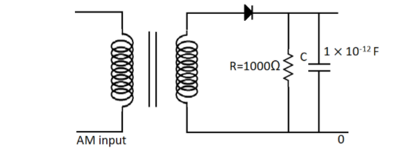
In the given detector circuit, the suitable value of carrier frequency is :-
(A) $ \ll {10^9}Hz$
(B) $ \ll {10^5}Hz$
(C) $ \gg {10^9}Hz$
(D) None of these.
Answer
242.4k+ views
Hint: In this detector circuit, using the values for the resistance and the capacitance, we can find their product. Now using the condition for the carrier frequency in detector circuit that is, $\dfrac{1}{{{f_c}}} \ll RC$, we can find the suitable value of the carrier frequency.
Formula UsedIn this solution we will be using the following formula,
$\dfrac{1}{{{f_c}}} \ll RC$
where ${f_c}$ is the carrier frequency,
$R$ is the resistance and
$C$ is the capacitance
Complete Step by Step Solution
For a detector circuit, the carrier frequency, the resistance and the capacitance are all related by the formula,
$\dfrac{1}{{{f_c}}} \ll RC$
Now we can take reciprocal on both the sides. So we will get,
${f_c} \gg \dfrac{1}{{RC}}$
The inequality sign also gets reversed on taking the reciprocal.
Now we are given in the diagram in the question that the resistance has a value,
$R = 1000\Omega $
And the capacitance is given as,
$C = 1 \times {10^{ - 12}}F$
Therefore, the RHS of the previous equation is the product of the resistance and capacitance. So n doing the product we get,
$R \times C = 1000 \times 1 \times {10^{ - 12}}$
So this gives us a value of,
$R \times C = {10^{ - 9}}$
Therefore, we can substitute this value in the equation and get,
${f_c} \gg \dfrac{1}{{{{10}^{ - 9}}}}$
Hence this becomes,
${f_c} \gg {10^9}Hz$
So the carrier frequency should have a suitable value of $ \gg {10^9}Hz$
So the correct answer is option C.
NoteThe carrier frequency is the frequency of the carrier wave that is modulated to transmit signals.
A carrier signal is used for efficient transmission in order to reduce the wavelength. The carrier signal is usually a simple single frequency sinusoid. A detector circuit is used to extract information from a modulated radio frequency current or voltage.
Recently Updated Pages
JEE Main 2025-26 Mock Tests: Free Practice Papers & Solutions
JEE Main 2025-26 Experimental Skills Mock Test – Free Practice
JEE Main 2025-26 Electronic Devices Mock Test: Free Practice Online
JEE Main 2025-26 Atoms and Nuclei Mock Test – Free Practice Online
JEE Main 2025-26: Magnetic Effects of Current & Magnetism Mock Test
JEE Main Mock Test 2025: Properties of Solids and Liquids
Trending doubts
JEE Main 2026: Session 1 Results Out and Session 2 Registration Open, City Intimation Slip, Exam Dates, Syllabus & Eligibility
Ideal and Non-Ideal Solutions Explained for Class 12 Chemistry
JEE Main Participating Colleges 2026 - A Complete List of Top Colleges
Degree of Dissociation: Meaning, Formula, Calculation & Uses
Understanding the Angle of Deviation in a Prism
Hybridisation in Chemistry – Concept, Types & Applications
Other Pages
CBSE Class 12 Physics Question Paper 2026: Download SET-wise PDF with Answer Key & Analysis
JEE Advanced Marks vs Ranks 2025: Understanding Category-wise Qualifying Marks and Previous Year Cut-offs
Dual Nature of Radiation and Matter Class 12 Physics Chapter 11 CBSE Notes - 2025-26
CBSE Class 10 Sanskrit Set 4 52 Question Paper 2025 – PDF, Solutions & Analysis
JEE Advanced Weightage 2025 Chapter-Wise for Physics, Maths and Chemistry
Understanding the Electric Field of a Uniformly Charged Ring