


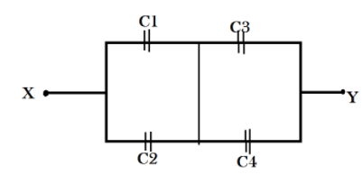
In the circuit shown below, ${C_1} = 10\mu F$, ${C_2} = {C_3} = 20\mu F$, and ${C_4} = 40\mu F$. If the charge on ${C_1}$ is $20\mu F$, then the potential difference between $X$ and $Y$ is:
A) $2V$
B) $3V$
C) $6V$
D) $3.5V$
Answer
232.8k+ views
Hint: when capacitors are in series connection, the ratio of their capacitance is equal to the ratio of the charge passing through them. This relation helps us find the value of charge through ${C_2}$. We will use this charge value in determining the potential difference across ${C_2}$. Also, the sum of their charges will be equal to the total charge on their positive plates.
As ${C_3}$ and ${C_4}$ are in series, the resultant of their capacitance will be additive. Because charge in a circuit will be constant, the charge found out in the loop of ${C_1}$ and ${C_2}$ is the charge in the loop of ${C_3}$ and ${C_4}$. Thus we will be able to find out the potential difference across ${C_3}$.
Therefore, we will add both the potential difference and find out the given circuit’s potential difference value.
Formulae used: Ratio of their capacitance in ${C_1}$ and ${C_2}$ is equal to the ratio of the charge passing through them:
$\dfrac{{{Q_1}}}{{{Q_2}}} = \dfrac{{{C_1}}}{{{C_2}}}$
Where ${C_1}$ and ${C_2}$ are the capacitance values and is expressed in microFarads$(\mu F)$ and ${Q_1}$ and ${Q_2}$ are the charge values and is expressed in microCoulombs $(\mu C)$.
Sum of their charges: $Q = {Q_1} + {Q_2}$
Where $Q$ is the sum of charge on their positive plates of ${C_1}$ and ${C_2}$.
Potential difference across ${C_2}$: ${V_2} = \dfrac{{{Q_2}}}{{{C_2}}}$
Where ${V_2}$ is the potential difference value across ${C_2}$ and is expressed in volts $(V)$.
Resultant of their capacitance of ${C_3}$ and ${C_4}$: \[{C_3} + {C_4}\]
Where ${C_3}$ and ${C_4}$ are the capacitance values and are expressed in microFarads$(\mu F)$.
Potential difference across ${C_3}$: \[{V_3} = \dfrac{{{Q_1} + {Q_2}}}{{{C_3} + {C_4}}}\]
Where is the potential difference value across ${C_3}$ and is expressed in volts $(V)$.
Given circuit’s potential difference value: $V = {V_2} + {V_3}$
Where $V$is the potential difference values of the entire circuit and is expressed in volts $(V)$.
Complete step by step solution:
From the given circuit we determine that ${C_1}$ & ${C_2}$ and ${C_3}$ & ${C_4}$ are in parallel connection with each other’s loops. And ${C_1}$ & ${C_2}$ and ${C_3}$ & ${C_4}$ are in series among themselves.
Let, ${Q_1},{Q_2},{Q_3},{Q_4}$be the charges on \[{C_1},{C_2},{C_3},{C_4}\].
We know that for capacitors in series connection, the ratio of their capacitance is equal to the ratio of the charge passing through them.
Therefore, $\dfrac{{{Q_1}}}{{{Q_2}}} = \dfrac{{{C_1}}}{{{C_2}}}$ .
Substituting the values we get,
\[
\dfrac{{20}}{{{Q_2}}} = \dfrac{{10}}{{20}} \\
\Rightarrow {Q_2} = 40\mu C \\
\]
The potential difference across ${Q_2}$ is $\dfrac{{{Q_2}}}{{{C_2}}}$.
Substituting the values we get,
${V_2} = \dfrac{{{Q_2}}}{{{C_2}}} = \dfrac{{40}}{{20}}$
$ \Rightarrow {V_2} = 2V$
Also, the total charge on the positive plates of ${C_1}$ and ${C_2}$ $Q = {Q_1} + {Q_2}$
Substituting the values we get,
$
Q = 20 + 40 \\
\Rightarrow Q = 60\mu C \\
$
For the second loop of capacitors which are connected in series, the summation of their capacitances is \[{C_3} + {C_4}\].
Substituting the values we find the total capacitance of the loop to be \[20 + 40 = 60\mu F\].
We know that the amount of charge entering a circuit through one end is equal to the amount of charge exiting through the other end.
Therefore we can determine the potential difference across ${C_3}$ to be \[{V_3} = \dfrac{{{Q_1} + {Q_2}}}{{{C_3} + {C_4}}}\].
Substituting the values we get,
\[
{V_3} = \dfrac{{60}}{{60}} \\
\Rightarrow {V_3} = 1V \\
\]
Finally we can calculate the potential difference across $X$ and $Y$ with $V = {V_2} + {V_3}$.
Substituting the values we get the potential difference values of the entire circuit,
$
V = {V_2} + {V_3} = 2V + 1V \\
\Rightarrow V = 1V \\
$
Additional information: capacitors are used to store charge for future requirement of a circuit. Therefore, we add the capacitance value for two capacitors in series connection.
In conclusion, the potential difference between $X$ and $Y$ is $1V$.
Note: The charge is conserved in a given system. Calculating it only for the first loop will be sufficient. Double calculation will lead to error in further calculations involving charge.
Recently Updated Pages
JEE Main 2023 April 6 Shift 1 Question Paper with Answer Key
JEE Main 2023 April 6 Shift 2 Question Paper with Answer Key
JEE Main 2023 (January 31 Evening Shift) Question Paper with Solutions [PDF]
JEE Main 2023 January 30 Shift 2 Question Paper with Answer Key
JEE Main 2023 January 25 Shift 1 Question Paper with Answer Key
JEE Main 2023 January 24 Shift 2 Question Paper with Answer Key
Trending doubts
JEE Main 2026: Session 2 Registration Open, City Intimation Slip, Exam Dates, Syllabus & Eligibility
JEE Main 2026 Application Login: Direct Link, Registration, Form Fill, and Steps
Understanding the Angle of Deviation in a Prism
Hybridisation in Chemistry – Concept, Types & Applications
How to Convert a Galvanometer into an Ammeter or Voltmeter
Understanding Uniform Acceleration in Physics
Other Pages
JEE Advanced Marks vs Ranks 2025: Understanding Category-wise Qualifying Marks and Previous Year Cut-offs
Dual Nature of Radiation and Matter Class 12 Physics Chapter 11 CBSE Notes - 2025-26
Understanding the Electric Field of a Uniformly Charged Ring
JEE Advanced Weightage 2025 Chapter-Wise for Physics, Maths and Chemistry
Derivation of Equation of Trajectory Explained for Students
Understanding Electromagnetic Waves and Their Importance