


In a common emitter transistor circuit the base current is \[40\mu {\text{A}}\], then \[{V_{BE}}\] is:
A) $2V$
B) $0.2V$
C) $0.8V$
D) $Zero$
Answer
232.8k+ views
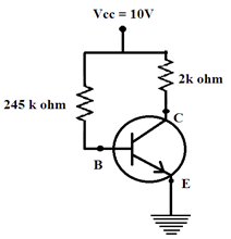
Hint: By using current formula $V = IR$, the current flowing through a voltage V and resistance R. show the figure in common emitter transistor circuit, and given values are base current is \[40\mu {\text{A}}\], voltage current is \[{V_{CC}} = 10V\]and the base resistance is $245K\Omega $. Find the base emitter voltage\[{V_{BE}}\].
Complete step by step answer:
The given values are,
Base current is\[40\mu {\text{A}}\]
Voltage current\[{I_V} = {V_{CC}} = 10V\]
Base resistance ${R_B} = 245K\Omega $
We know,
Input voltage ${I_V} = {V_{BE}} + ({I_B}) \times ({R_B})$
Where,
${I_B}$ Is the base current, and
${R_B}$ Is the resistance offered in the base region.
${V_{BE}} = {I_V} - {I_B} \times {R_B}$
\[{I_V} = {V_{CC}} = 10V\] And
${I_B} = 40\mu A$
$ \Rightarrow 40 \times {10^{ - 6}}A$
Also,${R_B} = 245K\Omega $
$ \Rightarrow 245 \times {10^3}\Omega $ [From the figure]
Putting their respective values, we get:
${V_{BE}} = 10 - (40 \times {10^{ - 6}}A)(245 \times {10^3}\Omega )$
On simplification the bracket term and we get
$ \Rightarrow (10 - 9.8)V$
On subtracting we get,
$ \Rightarrow 0.2V$
Therefore, option (B) is the correct answer.
Additional information:
Common emitter transistor:
As such the common emitter configuration may be a good all round circuit to be used in many applications. It's also worth noting at this stage that the common emitter transistor amplifier inverts the signal at the input. Therefore if a waveform that's rising enters the input of the common emitter amplifier, it'll cause the output voltage to fall.
Note: Advantages of Common Emitter amplifier:
1. A common emitter amplifier is inverting and has low I/p impedance
2. High output impedance
3. High voltage gain.
4. High current gain.
Disadvantages of Common Emitter amplifier:
1. It’s a high output resistance.
2. It responds poorly to high frequencies.
3. Its high thermal instabilities.
4. Its voltage gain is extremely unstable
Recently Updated Pages
JEE Main 2023 April 6 Shift 1 Question Paper with Answer Key
JEE Main 2023 April 6 Shift 2 Question Paper with Answer Key
JEE Main 2023 (January 31 Evening Shift) Question Paper with Solutions [PDF]
JEE Main 2023 January 30 Shift 2 Question Paper with Answer Key
JEE Main 2023 January 25 Shift 1 Question Paper with Answer Key
JEE Main 2023 January 24 Shift 2 Question Paper with Answer Key
Trending doubts
JEE Main 2026: Session 2 Registration Open, City Intimation Slip, Exam Dates, Syllabus & Eligibility
JEE Main 2026 Application Login: Direct Link, Registration, Form Fill, and Steps
Understanding the Angle of Deviation in a Prism
Hybridisation in Chemistry – Concept, Types & Applications
How to Convert a Galvanometer into an Ammeter or Voltmeter
Understanding Uniform Acceleration in Physics
Other Pages
JEE Advanced Marks vs Ranks 2025: Understanding Category-wise Qualifying Marks and Previous Year Cut-offs
Dual Nature of Radiation and Matter Class 12 Physics Chapter 11 CBSE Notes - 2025-26
Understanding the Electric Field of a Uniformly Charged Ring
JEE Advanced Weightage 2025 Chapter-Wise for Physics, Maths and Chemistry
Derivation of Equation of Trajectory Explained for Students
Understanding Electromagnetic Waves and Their Importance