


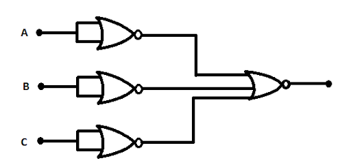
Identify the operation performed by the circuit given below:
A. NOT
B. OR
C. AND
D. NAND
Answer
260.4k+ views
Hint: This question contains the concept of logic gate. Before attempting the question, one must have an idea about the logic gate and its symbols. The combination of inputs implemented to a logic gate determines its output. Logic gates use Boolean algebra to take out logical processes.
Complete step by step solution:
A digital circuit's building blocks are logic gates, which perform the numerous logical operations expected by any digital circuit. These can accept two or more inputs but only give one output. Logic gates are identified in almost every digital device we use nowadays. Logic gates are utilized in the architecture of our phones, laptops, tablets, and memory devices.
The basic logic gates are OR, AND, and NOT, but there are some universal logic gates like NAND and NOR. We can operate a very complicated logic function in any complex circuitry by combining several logic gates.
In the given circuit all three inputs are connected to the particular NOR gate. A NOR gate, also known as a "not OR gate," is a logic gate that provides a high output (1) only if all of its inputs are false, and a low output (0) otherwise. As a result, the NOR gate is the inverse of the OR gate, and its circuit is created by connecting an OR gate to a NOT gate. Like an OR gate, a NOR gate can have any number of input probes but only one output probe. Thus, outputs for particular input will be the inverse of its input. The total output of the circuit can be realized using boolean algebra. The given circuit is modified in the following diagram:
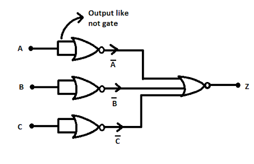
Now, the output for the first gate is $\bar{A}$.
For, the second gate is $\bar{B}$.
Similarly, the third gate output is $\bar{C}$.
Thus, the total output of the circuit can be written as:
$Z=\bar{\bar{A}+\bar{B}+\bar{C}}$
Further simplifying,
$Z=\bar{\bar{A}}.\bar{\bar{B}}.\bar{\bar{C}}$ (using De Morgan’s theorem)
Again,
$Z=A.B.C$ (Boolean law)
Which is the output of the AND gate.
Therefore, The operation performed by the given circuit is AND operation.
Note: Be careful while performing logical operations. The OR logic gate is used to add the applied input signals. The AND logic gate multiplies the applied input signals and produces a single output. When used in any circuit, NOT logic circuits perform the inversion function.
Complete step by step solution:
A digital circuit's building blocks are logic gates, which perform the numerous logical operations expected by any digital circuit. These can accept two or more inputs but only give one output. Logic gates are identified in almost every digital device we use nowadays. Logic gates are utilized in the architecture of our phones, laptops, tablets, and memory devices.
The basic logic gates are OR, AND, and NOT, but there are some universal logic gates like NAND and NOR. We can operate a very complicated logic function in any complex circuitry by combining several logic gates.
In the given circuit all three inputs are connected to the particular NOR gate. A NOR gate, also known as a "not OR gate," is a logic gate that provides a high output (1) only if all of its inputs are false, and a low output (0) otherwise. As a result, the NOR gate is the inverse of the OR gate, and its circuit is created by connecting an OR gate to a NOT gate. Like an OR gate, a NOR gate can have any number of input probes but only one output probe. Thus, outputs for particular input will be the inverse of its input. The total output of the circuit can be realized using boolean algebra. The given circuit is modified in the following diagram:
Now, the output for the first gate is $\bar{A}$.
For, the second gate is $\bar{B}$.
Similarly, the third gate output is $\bar{C}$.
Thus, the total output of the circuit can be written as:
$Z=\bar{\bar{A}+\bar{B}+\bar{C}}$
Further simplifying,
$Z=\bar{\bar{A}}.\bar{\bar{B}}.\bar{\bar{C}}$ (using De Morgan’s theorem)
Again,
$Z=A.B.C$ (Boolean law)
Which is the output of the AND gate.
Therefore, The operation performed by the given circuit is AND operation.
Note: Be careful while performing logical operations. The OR logic gate is used to add the applied input signals. The AND logic gate multiplies the applied input signals and produces a single output. When used in any circuit, NOT logic circuits perform the inversion function.
Recently Updated Pages
Algebra Made Easy: Step-by-Step Guide for Students
JEE Isolation, Preparation and Properties of Non-metals Important Concepts and Tips for Exam Preparation
JEE Energetics Important Concepts and Tips for Exam Preparation
Chemical Properties of Hydrogen - Important Concepts for JEE Exam Preparation
JEE General Topics in Chemistry Important Concepts and Tips
JEE Amino Acids and Peptides Important Concepts and Tips for Exam Preparation
Trending doubts
JEE Main 2026: Exam Dates, Session 2 Updates, City Slip, Admit Card & Latest News
JEE Main Participating Colleges 2026 - A Complete List of Top Colleges
Hybridisation in Chemistry – Concept, Types & Applications
Understanding the Electric Field of a Uniformly Charged Ring
Derivation of Equation of Trajectory Explained for Students
Understanding Atomic Structure for Beginners
Other Pages
CBSE Class 12 Physics Question Paper 2026: Download SET-wise PDF with Answer Key & Analysis
JEE Advanced 2026 Notification Out with Exam Date, Registration (Extended), Syllabus and More
JEE Advanced Marks vs Ranks 2025: Understanding Category-wise Qualifying Marks and Previous Year Cut-offs
JEE Advanced Weightage Chapter Wise 2026 for Physics, Chemistry, and Mathematics
How to Convert a Galvanometer into an Ammeter or Voltmeter
Understanding Uniform Acceleration in Physics