


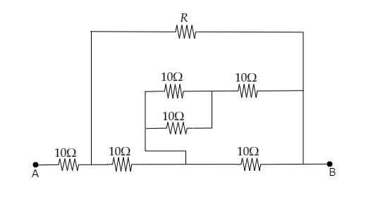
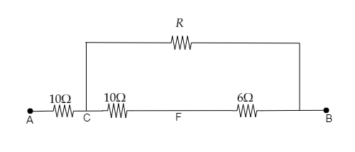
Find that value of $R$ for which the net resistance of the circuit is 18 ohms.
A) $8\Omega $
B) $10\Omega $
C) $16\Omega $
D) $24\Omega $
Answer
243.6k+ views
Hint: The value of the resistance $R$ can be obtained by reducing the circuit. The resistance of two resistors in series will be the sum of their resistances and the resistance of two resistors connected in parallel will be the sum of the reciprocal of their resistances.
Formula Used:
1) The effective resistance of two resistors in series is given by, ${R_{eff}} = {R_1} + {R_2}$ where ${R_1}$ and ${R_2}$ are the resistances of the two resistors.
2) The effective resistance of two resistors in parallel is given by, ${R_{eff}} = \dfrac{{{R_1}{R_2}}}{{{R_1} + {R_2}}}$ where ${R_1}$ and ${R_2}$ are the resistances of the two resistors.
Complete step by step answer:
Step 1: Sketch the arrangement of the resistors and mark each junction.
In the above figure, the point of contact between two resistors is marked.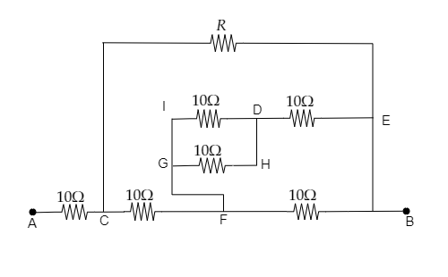
The net resistance of the above circuit is given to be ${R_{net}} = 18\Omega $
Step 2: Reduce loop IDHG.
In the loop IDHG, the two resistors are connected in parallel. Then the two resistors can be replaced by their effective resistance given by, ${R_{eff}} = \dfrac{{{R_{ID}}{R_{GH}}}}{{{R_{ID}} + {R_{GH}}}} = \dfrac{{10 \times 10}}{{10 + 10}} = 5\Omega $
Then the reduced circuit is given below.
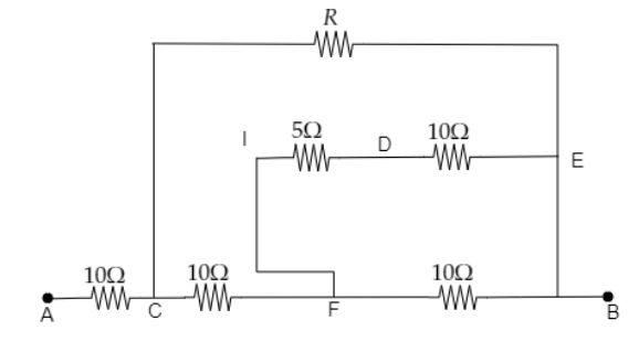
Step 3: Reduce the resistors connected across ID and DE.
The two resistors connected across ID and DE are in series. So these resistors can be replaced by their effective resistance given by, ${R_{eff}} = {R_{ID}} + {R_{DE}} = 5 + 10 = 15\Omega $
Then the reduced circuit is given below.
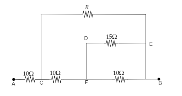
Step 4: Reduce the circuit for the resistors in the loop DEFB.
The two resistors connect across DE and FB are connected in parallel and hence they are replaced by their effective resistance given by, ${R_{eff}} = \dfrac{{{R_{DE}}{R_{FB}}}}{{{R_{DE}} + {R_{FB}}}} = \dfrac{{15 \times 10}}{{15 + 10}} = 6\Omega $
The reduced circuit is given below.
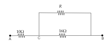
Step 5: Reduce the resistors connected across CF and FB.
The two resistors connected across CF and FB are in series. So these resistors can be replaced by their effective resistance given by, ${R_{eff}} = {R_{CF}} + {R_{FB}} = 10 + 6 = 16\Omega $
Then the reduced circuit is given below.
Step 6: Reduce the circuit for the resistors connected across CB.
The two resistors connect across CB are connected in parallel and hence they are replaced by their effective resistance given by, ${R_{eff}} = \dfrac{{16R}}{{R + 16}}\Omega $
The reduced circuit is given below.
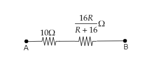
Now the net resistance will be the sum of the above two resistances as they are connected in series.
i.e., ${R_{net}} = 10 + \dfrac{{16R}}{{R + 16}} = 18\Omega $
$ \Rightarrow \dfrac{{16R}}{{R + 16}} = 8$
On cross-multiplying we get, $16R = 8R + 128$
$ \Rightarrow R = 16\Omega $
Thus the value of the resistance is $R = 16\Omega $ .
Hence the correct option is C.
Note: Two resistors are said to be connected in parallel if both of their ends are connected to each other. This type of connection is first observed in the loop IDHG. In this loop, both the resistors have the same value of resistance and so the effective resistance of that loop can also be obtained as ${R_{eff}} = \dfrac{{{R_{ID}}}}{2} = \dfrac{{10}}{2} = 5\Omega $ or ${R_{eff}} = \dfrac{{{R_{GH}}}}{2} = \dfrac{{10}}{2} = 5\Omega $. Two resistors are said to be connected in series if one of their ends is connected together.
Formula Used:
1) The effective resistance of two resistors in series is given by, ${R_{eff}} = {R_1} + {R_2}$ where ${R_1}$ and ${R_2}$ are the resistances of the two resistors.
2) The effective resistance of two resistors in parallel is given by, ${R_{eff}} = \dfrac{{{R_1}{R_2}}}{{{R_1} + {R_2}}}$ where ${R_1}$ and ${R_2}$ are the resistances of the two resistors.
Complete step by step answer:
Step 1: Sketch the arrangement of the resistors and mark each junction.
In the above figure, the point of contact between two resistors is marked.
The net resistance of the above circuit is given to be ${R_{net}} = 18\Omega $
Step 2: Reduce loop IDHG.
In the loop IDHG, the two resistors are connected in parallel. Then the two resistors can be replaced by their effective resistance given by, ${R_{eff}} = \dfrac{{{R_{ID}}{R_{GH}}}}{{{R_{ID}} + {R_{GH}}}} = \dfrac{{10 \times 10}}{{10 + 10}} = 5\Omega $
Then the reduced circuit is given below.
Step 3: Reduce the resistors connected across ID and DE.
The two resistors connected across ID and DE are in series. So these resistors can be replaced by their effective resistance given by, ${R_{eff}} = {R_{ID}} + {R_{DE}} = 5 + 10 = 15\Omega $
Then the reduced circuit is given below.
Step 4: Reduce the circuit for the resistors in the loop DEFB.
The two resistors connect across DE and FB are connected in parallel and hence they are replaced by their effective resistance given by, ${R_{eff}} = \dfrac{{{R_{DE}}{R_{FB}}}}{{{R_{DE}} + {R_{FB}}}} = \dfrac{{15 \times 10}}{{15 + 10}} = 6\Omega $
The reduced circuit is given below.
Step 5: Reduce the resistors connected across CF and FB.
The two resistors connected across CF and FB are in series. So these resistors can be replaced by their effective resistance given by, ${R_{eff}} = {R_{CF}} + {R_{FB}} = 10 + 6 = 16\Omega $
Then the reduced circuit is given below.
Step 6: Reduce the circuit for the resistors connected across CB.
The two resistors connect across CB are connected in parallel and hence they are replaced by their effective resistance given by, ${R_{eff}} = \dfrac{{16R}}{{R + 16}}\Omega $
The reduced circuit is given below.
Now the net resistance will be the sum of the above two resistances as they are connected in series.
i.e., ${R_{net}} = 10 + \dfrac{{16R}}{{R + 16}} = 18\Omega $
$ \Rightarrow \dfrac{{16R}}{{R + 16}} = 8$
On cross-multiplying we get, $16R = 8R + 128$
$ \Rightarrow R = 16\Omega $
Thus the value of the resistance is $R = 16\Omega $ .
Hence the correct option is C.
Note: Two resistors are said to be connected in parallel if both of their ends are connected to each other. This type of connection is first observed in the loop IDHG. In this loop, both the resistors have the same value of resistance and so the effective resistance of that loop can also be obtained as ${R_{eff}} = \dfrac{{{R_{ID}}}}{2} = \dfrac{{10}}{2} = 5\Omega $ or ${R_{eff}} = \dfrac{{{R_{GH}}}}{2} = \dfrac{{10}}{2} = 5\Omega $. Two resistors are said to be connected in series if one of their ends is connected together.
Recently Updated Pages
JEE Main 2026 Session 2 City Intimation Slip & Exam Date: Expected Date, Download Link
JEE Main 2026 Session 2 Application Form: Reopened Registration, Dates & Fees
JEE Main 2026 Session 2 Registration (Reopened): Last Date, Fees, Link & Process
WBJEE 2026 Registration Started: Important Dates Eligibility Syllabus Exam Pattern
JEE Main 2025-26 Mock Tests: Free Practice Papers & Solutions
JEE Main 2025-26 Experimental Skills Mock Test – Free Practice
Trending doubts
JEE Main 2026: Session 1 Results Out and Session 2 Registration Open, City Intimation Slip, Exam Dates, Syllabus & Eligibility
Ideal and Non-Ideal Solutions Explained for Class 12 Chemistry
Understanding the Angle of Deviation in a Prism
Understanding Differential Equations: A Complete Guide
Hybridisation in Chemistry – Concept, Types & Applications
Understanding the Electric Field of a Uniformly Charged Ring
Other Pages
CBSE Class 12 Physics Question Paper 2026: Download SET-wise PDF with Answer Key & Analysis
JEE Advanced Marks vs Ranks 2025: Understanding Category-wise Qualifying Marks and Previous Year Cut-offs
JEE Advanced 2026 - Exam Date (Released), Syllabus, Registration, Eligibility, Preparation, and More
Dual Nature of Radiation and Matter Class 12 Physics Chapter 11 CBSE Notes - 2025-26
JEE Advanced Weightage 2025 Chapter-Wise for Physics, Maths and Chemistry
Understanding the Block and Tackle System