


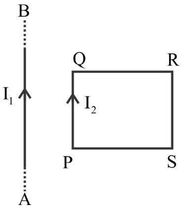
AB is a long wire carrying a current ${I_1}$ and PQRS is a rectangular loop carrying current ${I_2}$ (as shown in the figure) which is among the following statements are correct?
1. Arm PQ will get attracted to wire AB and the arm RS will get replied from wire AB.
2. Net force on loop is zero
3. Forces on arms PQ and RS will be equal and opposite
4. Forces on arm QR and SP will be zero
5. Forces on arm QR and SP will be equal and opposite
(A) Only (i) and (v)
(B) Only (i) (ii) and (iv)
(C) Only (i) (ii) (iii)
(D) Only (ii) and (iv)
Answer
232.8k+ views
Hint To analyse the given statements whether it is correct or wrong we have to know the concepts related with the current carrying conductor. We should revise the behaviour of two current carrying conductors placed close to each other and about the current carrying rectangular loop.
Complete step by step answer
Given,
Current flowing through the wire ab is ${I_1}$
Current flowing through the rectangular loop is ${I_2}$
Let us analyse the given statement one by one
The first statement says that the arm PQ will get attracted to wire AB and the arm RS will get replied from wire AB.
When current passes through a conductor the current flowing through the conductor induces a magnetic field around it.
If we take two current carrying conductors placed in a short distance r. Then both the current carrying conductors produce their own induced magnetic fields. This induced magnetic field of force affects the direction of force of current.
The two conductors will experience an attractive force towards each other if the both of the current carrying conductors carry current in the same direction due to the induced magnetic field and the two conductors will experience a repulsive force towards each other if both of the current carrying conductors carry current in opposite directions.
We can see in the diagram that the current in wire AB and the arm PQ is in the same direction, so they will attract each other i.e. the arm PQ will get attracted to wire AB. The current in wire AB and the arm RS is in different direction, so they will repel each other i.e. RS will get replies from wire AB.
Hence the first statement is correct
The second statement is Net force on loop is zero
The force on a current carrying conductor is given by the formula
$ \Rightarrow I \times (\mathop B\limits^ \to \times \mathop L\limits^ \to )$
Where,
I is the current
B is the magnetic field
L is the length of the wire
Here we have different values of current ${I_1}$ in the wire and ${I_2}$ in the loop. So, they will have different forces and the net force on the loop will not be zero
So, the second statement is wrong
The third statement is Forces on arms PQ and RS will be equal and opposite.
The fourth and fifth statement is forces on arm QR and SP will be zero and forces on arm QR and SP will be equal and opposite.
As we have seen above,
The force on a current carrying conductor is given by the formula
$ \Rightarrow I \times (\mathop B\limits^ \to \times \mathop L\limits^ \to )$
In the loop the length of the arm PQ and RS are same and the current flowing through them is also same i.e. ${I_2}$. The magnetic field is given by the formula
$ \Rightarrow \mathop B\limits^ \to = \dfrac{{{\mu _0}I}}{{2\pi r}}$
In this formula we can see that both the arms vary with distance. The distance of arm PQ from the wire AB will be short and the distance of the arm PQ from the arm PS will be long. So the forces on arms PQ and RS will not be equal but the current flowing through them will be in the opposite direction.
So, forces on arms PQ and RS will be different and opposite.
The third statement is wrong.
The arm PR and PS are in the same distance from the wire AB so the Forces on arm QR and SP will be equal and opposite as they carry current in different directions. This proves that Forces on arm QR and SP will not be zero.
The fourth statement is wrong and the fifth statement is correct.
From the above discussion we can see that the statement one and five are correct.
Hence the correct answer is option (A) Only (i) and (v)
Note It is mentioned that the current in arm RS and PS is in the opposite direction to PQ and QR. Follow the direction of current you can see that the current goes downside in arm RS and upward in PQ . The direction of current is left to right in QR and right to left in PS.
Recently Updated Pages
JEE Main 2023 April 6 Shift 1 Question Paper with Answer Key
JEE Main 2023 April 6 Shift 2 Question Paper with Answer Key
JEE Main 2023 (January 31 Evening Shift) Question Paper with Solutions [PDF]
JEE Main 2023 January 30 Shift 2 Question Paper with Answer Key
JEE Main 2023 January 25 Shift 1 Question Paper with Answer Key
JEE Main 2023 January 24 Shift 2 Question Paper with Answer Key
Trending doubts
JEE Main 2026: Session 2 Registration Open, City Intimation Slip, Exam Dates, Syllabus & Eligibility
JEE Main 2026 Application Login: Direct Link, Registration, Form Fill, and Steps
Understanding the Angle of Deviation in a Prism
Hybridisation in Chemistry – Concept, Types & Applications
How to Convert a Galvanometer into an Ammeter or Voltmeter
Understanding Uniform Acceleration in Physics
Other Pages
JEE Advanced Marks vs Ranks 2025: Understanding Category-wise Qualifying Marks and Previous Year Cut-offs
Dual Nature of Radiation and Matter Class 12 Physics Chapter 11 CBSE Notes - 2025-26
Understanding the Electric Field of a Uniformly Charged Ring
JEE Advanced Weightage 2025 Chapter-Wise for Physics, Maths and Chemistry
Derivation of Equation of Trajectory Explained for Students
Understanding Electromagnetic Waves and Their Importance