


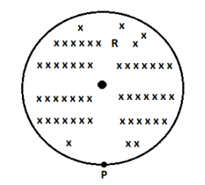
A uniform magnetic field of induction $B$ is confined to a cylindrical region of radius $R$. The magnetic field is increasing at a constant ratio of $\dfrac{{dB}}{{dt}}$. An electron of charge $q$, placed at the point $P$ on the periphery of the field experiences an acceleration:
(A) $\dfrac{1}{2}\dfrac{{eR}}{m}\dfrac{{dB}}{{dt}}$ toward left
(B) $\dfrac{1}{2}\dfrac{{eR}}{m}\dfrac{{dB}}{{dt}}$ toward right
(C) $\dfrac{{eR}}{m}\dfrac{{dB}}{{dt}}$ toward left
(D) $\dfrac{1}{2}\dfrac{{eR}}{m}\dfrac{{dB}}{{dt}}$ zero
Answer
257.1k+ views
Hint: Here we consider a magnetic field that is uniform and confined to a cylindrical region. The magnetic field is increasing at a constant ratio. If we place an electron at a point on the periphery of the field, it will experience an acceleration. Here we have to find the acceleration experienced by the electron placed at the periphery of the cylindrical region of a uniform magnetic field.
Complete step by step solution:
There will be an electric field induced at the point $P$.
The electric field induced at this point can be written as, $\int {E.dl = \dfrac{{d(AB)}}{{dt}}} $
where $E$ stands for the electric field $\;dl$ stands for the small element of length, $A$ stands for the area of the region, and $B$ stands for the magnetic field.
The above equation can be written as,
$\Rightarrow$ $E.\int {dl = A\dfrac{{dB}}{{dt}}} $
From the figure, we can write
$\int {dl = 2\pi R} $
and $A = \pi {R^2}$
Substituting these values within the above equation, we get
$E\left( {2\pi R} \right) = \left( {\pi {R^2}} \right)\dfrac{{dB}}{{dt}}$
From the above equation, we can write
$E = \dfrac{{\pi {R^2}}}{{2\pi R}}\dfrac{{dB}}{{dt}}$
Cancelling the common terms, we get
$E = \dfrac{R}{2}\dfrac{{dB}}{{dt}}$
Applying the right-hand thumb rule, if the curl of the fingers represents the direction of the induced electric field the thumb points towards the change in the magnetic field.
Hence here the induced electric field will be towards the right.
We know that the force, $F = ma$
From this, we can write
$\Rightarrow$ $a = \dfrac{F}{m}$
We can write the force here as, $F = eE$
where $e$ stands for the charge and $E$ stands for the electric field.
Then the above equation will become
$a = \dfrac{{eE}}{m}$
Substituting $E = \dfrac{R}{2}\dfrac{{dB}}{{dt}}$ in the above equation, we get
$\Rightarrow$ $a = \dfrac{1}{2}\dfrac{{eR}}{m}\dfrac{{dB}}{{dt}}$
The electron will be accelerated towards a direction opposite to the direction of the electric field.
Therefore the acceleration of the electron will be,
$\Rightarrow$ $a = \dfrac{1}{2}\dfrac{{eR}}{m}\dfrac{{dB}}{{dt}}$ toward left
The answer is:
Option (A): $a = \dfrac{1}{2}\dfrac{{eR}}{m}\dfrac{{dB}}{{dt}}$ toward left
Note:
The direction of electric and magnetic fields are found by applying various thumb rules. Whenever the magnetic flux linked with a closed circuit changes an e.m.f is induced in the circuit. This phenomenon is called electromagnetic induction. The e.m.f induced in the circuit is called induced e.m.f.
Recently Updated Pages
JEE Main Mock Test 2025-26: Electromagnetic Induction & Alternating Currents
JEE Main Mock Test 2025-26: Optics Chapter Practice Online
JEE Main 2025-26 Mock Test: Properties of Solids and Liquids
JEE Main Mock Test 2025-26: Dual Nature of Matter & Radiation
JEE Main 2025-26 Electromagnetic Waves Mock Test with Solutions
JEE Main 2025-26 Mock Test: Electronic Devices Chapter Practice
Trending doubts
JEE Main 2026: Exam Dates, Session 2 Updates, City Slip, Admit Card & Latest News
JEE Main Participating Colleges 2026 - A Complete List of Top Colleges
JEE Main 2026 Application Login: Direct Link, Registration, Form Fill, and Steps
JEE Main Colleges 2026: Complete List of Participating Institutes
JEE Main Marking Scheme 2026- Paper-Wise Marks Distribution and Negative Marking Details
Hybridisation in Chemistry – Concept, Types & Applications
Other Pages
CBSE Class 12 Physics Question Paper 2026: Download SET-wise PDF with Answer Key & Analysis
JEE Advanced 2026 - Exam Date (Released), Syllabus, Registration, Eligibility, Preparation, and More
JEE Advanced Marks vs Ranks 2025: Understanding Category-wise Qualifying Marks and Previous Year Cut-offs
JEE Advanced Weightage 2025 Chapter-Wise for Physics, Maths and Chemistry
Understanding the Electric Field of a Uniformly Charged Ring
Derivation of Equation of Trajectory Explained for Students