


A signal of \[20mV\] is applied to a common emitter amplifier circuit. Due to this, the change in base current and the change in collector current are $20\mu A$ and $2mA$. The load resistance is $10k\Omega $ , transconductance is:
A) $0.1{\Omega ^{ - 1}}$
B) $0.2{\Omega ^{ - 1}}$
C) $10{\Omega ^{ - 1}}$
D) None of these
Answer
233.4k+ views
Hint: In this question, we have the change in collector current $\Delta I{}_C$ and a signal which is added to the base-emitter voltage $\Delta {V_{BE}}$. We can use ${g_m} = \dfrac{{\Delta I{}_C}}{{\Delta {V_{BE}}}}$to find the transconductance ${g_m}$ of the common emitter amplifier circuit.
Complete step by step solution:
According to the question, a signal of \[20mV\] is applied to a common emitter amplifier circuit which means \[20mV\] is added to the base-emitter voltage($\Delta {V_{BE}}$). The load resistance ${R_L}$ in the common emitter amplifier circuit is $10k\Omega $. The change in base current $\Delta {I_B}$ is $20\mu A$ and the change in collector current $\Delta I{}_C$ is $2mA$.
We know that if $\Delta {V_{BE}}$ is bas-emitter voltage and $\Delta I{}_C$ is the collector current, then the transconductance ${g_m}$ of the common emitter amplifier circuit is given as-
${g_m} = \dfrac{{\Delta I{}_C}}{{\Delta {V_{BE}}}}$
Now, putting the values of $\Delta I{}_C = 2mA$ and $\Delta {V_{BE}} = 20mV$ in the equation, we get-
$
{g_m} = \dfrac{{2mA}}{{20mV}} \\
\Rightarrow {g_m} = \dfrac{1}{{10}}{\Omega ^{ - 1}} \\
\Rightarrow {g_m} = 0.1{\Omega ^{ - 1}} \\
$
Therefore, the transconductance of the common emitter amplifier circuit is $0.1{\Omega ^{ - 1}}$.
Hence, option A is correct.
Additional Information:
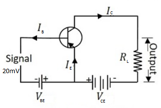
Above diagram shows a common emitter transistor. In this transistor, an emitter is common in both input circuit and output circuit. The base and emitter make the input circuit. The collector and the emitter make the output circuit. The input voltage is known as base-emitter voltage $\Delta {V_{BE}}$ and the output voltage is known as emitter-collector voltage $\Delta {V_{CE}}$. We can get the output current at the load resistance ${R_L}$.
Note: In this question, two types of change in current are given. We can calculate transconductance by using $\Delta I{}_C$ and $\Delta {V_{BE}}$. $\Delta {I_B}$ is not used in the calculation of transconductance. $\Delta {I_B}$ is used with $\Delta I{}_C$ to calculate the current gain of the circuit. The unit of the transconductance is always ${\Omega ^{ - 1}}$.
Complete step by step solution:
According to the question, a signal of \[20mV\] is applied to a common emitter amplifier circuit which means \[20mV\] is added to the base-emitter voltage($\Delta {V_{BE}}$). The load resistance ${R_L}$ in the common emitter amplifier circuit is $10k\Omega $. The change in base current $\Delta {I_B}$ is $20\mu A$ and the change in collector current $\Delta I{}_C$ is $2mA$.
We know that if $\Delta {V_{BE}}$ is bas-emitter voltage and $\Delta I{}_C$ is the collector current, then the transconductance ${g_m}$ of the common emitter amplifier circuit is given as-
${g_m} = \dfrac{{\Delta I{}_C}}{{\Delta {V_{BE}}}}$
Now, putting the values of $\Delta I{}_C = 2mA$ and $\Delta {V_{BE}} = 20mV$ in the equation, we get-
$
{g_m} = \dfrac{{2mA}}{{20mV}} \\
\Rightarrow {g_m} = \dfrac{1}{{10}}{\Omega ^{ - 1}} \\
\Rightarrow {g_m} = 0.1{\Omega ^{ - 1}} \\
$
Therefore, the transconductance of the common emitter amplifier circuit is $0.1{\Omega ^{ - 1}}$.
Hence, option A is correct.
Additional Information:
Above diagram shows a common emitter transistor. In this transistor, an emitter is common in both input circuit and output circuit. The base and emitter make the input circuit. The collector and the emitter make the output circuit. The input voltage is known as base-emitter voltage $\Delta {V_{BE}}$ and the output voltage is known as emitter-collector voltage $\Delta {V_{CE}}$. We can get the output current at the load resistance ${R_L}$.
Note: In this question, two types of change in current are given. We can calculate transconductance by using $\Delta I{}_C$ and $\Delta {V_{BE}}$. $\Delta {I_B}$ is not used in the calculation of transconductance. $\Delta {I_B}$ is used with $\Delta I{}_C$ to calculate the current gain of the circuit. The unit of the transconductance is always ${\Omega ^{ - 1}}$.
Recently Updated Pages
JEE Main 2023 April 6 Shift 1 Question Paper with Answer Key
JEE Main 2023 April 6 Shift 2 Question Paper with Answer Key
JEE Main 2023 (January 31 Evening Shift) Question Paper with Solutions [PDF]
JEE Main 2023 January 30 Shift 2 Question Paper with Answer Key
JEE Main 2023 January 25 Shift 1 Question Paper with Answer Key
JEE Main 2023 January 24 Shift 2 Question Paper with Answer Key
Trending doubts
JEE Main 2026: Session 2 Registration Open, City Intimation Slip, Exam Dates, Syllabus & Eligibility
JEE Main 2026 Application Login: Direct Link, Registration, Form Fill, and Steps
Understanding the Angle of Deviation in a Prism
Hybridisation in Chemistry – Concept, Types & Applications
How to Convert a Galvanometer into an Ammeter or Voltmeter
Understanding Uniform Acceleration in Physics
Other Pages
JEE Advanced Marks vs Ranks 2025: Understanding Category-wise Qualifying Marks and Previous Year Cut-offs
Dual Nature of Radiation and Matter Class 12 Physics Chapter 11 CBSE Notes - 2025-26
Understanding the Electric Field of a Uniformly Charged Ring
JEE Advanced Weightage 2025 Chapter-Wise for Physics, Maths and Chemistry
Derivation of Equation of Trajectory Explained for Students
Understanding Electromagnetic Waves and Their Importance