



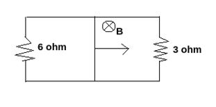
A rectangular loop with a sliding connector of $ length = 1.0\,m$ is situated in a uniform magnetic field $field = 2t$ perpendicular to the plane of loop. Resistance of the connector is $r = 2\Omega $ . Two resistance is $6\Omega $ and $3\Omega $ are connected as shown in the figure. The external force required to keep the connector moving with a constant velocity $v = 2m{s^{ - 1}}$
(A) $6N$
(B) $4N$
(C) $2N$
(D) $1N$
Answer
 Verified
319.5k+ views
Hint Uniform magnetic field: it is a kind of magnetic field that has the same magnitude and direction throughout the region which is under observation, thus the field line needs to be both parallel and space out evenly. Induced EMF: emf which is generated due to change in the magnetic flux is known as induced emf. Emf stands for electromotive force. $$E = vBl$$ . Magnetic force is the force of attraction or repulsion that comes into picture due to motion of electric charged particles $$F = ilB$$ .
Step-by-step solution
Given that, the resistance of the connector $2\Omega $
magnetic field - $$2t$$
two resistance - $6\Omega $ and $3\Omega $
velocity of moving connector - $$2m{s^{ - 1}}$$
Let’s calculate the induced emf generated in the circuit.
$$E = vBl$$
$$E = 2 \times 2 \times 1$$
$$E = 4V$$
Now, consider the two resistances $6\Omega $ and $3\Omega $ since they are in parallel connected then the resultant resistance will be $2\Omega $
So, now by considering the above findings we can have a figure as shown below
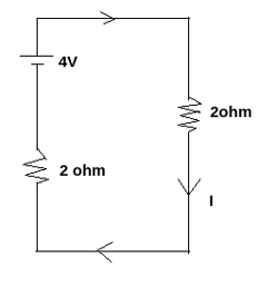
With the help of above diagram, we can easily find the value of $$I$$ (current) which is flowing through the circuit which is $$I = \dfrac{4}{{2 + 2}}$$ which will give us the value $$1\,ampere$$ is flowing in clockwise direction.
Now, calculation the magnetic force on connector by using formula $$F = ilB$$
$$F = 1 \times 1 \times 2$$
$$ \Rightarrow F = 2N$$
The direction of this force is towards the left.
So, as a result if we want to move our connector with a constant velocity, we need to apply force of $2N$
Therefore, option (a) will be the correct answer.
Note always try to go approach step by step otherwise questions like this can confuse a bit. Also, try to remember the formulas of electromotive force $$E = vBl$$ , magnetic force $$F = ilB$$ and also the formula to find the resultant of connected resistances for series connection formula will be $$R = {r_1} + {r_2} + ... + {r_n}$$ .
Step-by-step solution
Given that, the resistance of the connector $2\Omega $
magnetic field - $$2t$$
two resistance - $6\Omega $ and $3\Omega $
velocity of moving connector - $$2m{s^{ - 1}}$$
Let’s calculate the induced emf generated in the circuit.
$$E = vBl$$
$$E = 2 \times 2 \times 1$$
$$E = 4V$$
Now, consider the two resistances $6\Omega $ and $3\Omega $ since they are in parallel connected then the resultant resistance will be $2\Omega $
So, now by considering the above findings we can have a figure as shown below
With the help of above diagram, we can easily find the value of $$I$$ (current) which is flowing through the circuit which is $$I = \dfrac{4}{{2 + 2}}$$ which will give us the value $$1\,ampere$$ is flowing in clockwise direction.
Now, calculation the magnetic force on connector by using formula $$F = ilB$$
$$F = 1 \times 1 \times 2$$
$$ \Rightarrow F = 2N$$
The direction of this force is towards the left.
So, as a result if we want to move our connector with a constant velocity, we need to apply force of $2N$
Therefore, option (a) will be the correct answer.
Note always try to go approach step by step otherwise questions like this can confuse a bit. Also, try to remember the formulas of electromotive force $$E = vBl$$ , magnetic force $$F = ilB$$ and also the formula to find the resultant of connected resistances for series connection formula will be $$R = {r_1} + {r_2} + ... + {r_n}$$ .
Recently Updated Pages
Mass vs Weight: Key Differences Explained for Students
JEE Main Mock Test 2025-26: Electromagnetic Induction & Alternating Currents
JEE Main Mock Test 2025-26: Optics Chapter Practice Online
JEE Main 2025-26 Mock Test: Properties of Solids and Liquids
JEE Main 2025-26 Electromagnetic Waves Mock Test with Solutions
JEE Main 2025-26 Mock Test: Electronic Devices Chapter Practice
Trending doubts
JEE Main 2027: Registration Open, Session 1 & 2 Exam Dates, City Slip, Admit Card & Complete Guide
Derivation of Equation of Trajectory Explained for Students
JEE Main Correction Window 2026 Session 1 Dates Announced - Edit Form Details, Dates and Link
Electron Gain Enthalpy and Electron Affinity Explained
JEE Main Candidate Login 2027 (Active): Direct Link and Registration Steps
How to Convert a Galvanometer into an Ammeter or Voltmeter
Other Pages
CBSE Class 12 Physics Question Paper 2026: Download SET-wise PDF with Answer Key & Analysis
JEE Advanced 2026 Notification Out with Exam Date, Registration (Extended), Syllabus and More
Degree of Dissociation: Meaning, Formula, Calculation & Uses
Understanding Uniform Acceleration in Physics
Understanding the Electric Field of a Uniformly Charged Ring
Understanding Collisions: Types and Examples for Students