


The arrangement as shown in the figure is called as ?
Answer
537.6k+ views
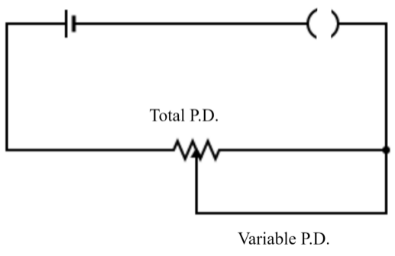
Hint: In the given diagram there is a voltage source, a key to close or open the circuit and a resistor. Also, there is one more wire which is connecting the circuit to a point that is somewhere in the middle of the resistor, which is labeled as ‘variable P.D’.
Complete answer:
Electrical circuits are closed paths in which electric current flows. A typical circuit includes a voltage or current source, a resistor or a device of some resistance value and other electrical or electronic devices such as capacitor, inductor, transmitter etc.
An electrical circuit of resistors has two basic forms, series combination or parallel combination.In a series combination, the electric current through the resistors is the same while the voltage across them is different; while in a parallel combination, the voltage across the resistors is the same but the current flowing through them is different.
Suppose many resistors are connected in series with each other and then to a voltage source, then the voltage across all of them gets divided in such a way that the voltage across any resistor \[{{R}_{x}}\] is given by: \[{{V}_{x}}(t)=V(t)\dfrac{{{R}_{x}}}{{{R}_{T}}}\], where \[{{R}_{T}}\] is the total resistance of the series combination. Voltage dividers are used for making potentiometers; in fact, they are also used in a wheat-stone bridge circuit and multimeter circuit.
Note: When a wire connects the voltage source to the resistor in such a way that one end of the wire divides the resistor into two parts, then basically the wire divides a single resistor into the combination of two series resistors, and since we know that in a series circuit the voltage gets divided across the resistors, that’s why the arrangement in the given figure is called as a voltage divider.
Recently Updated Pages
Three beakers labelled as A B and C each containing 25 mL of water were taken A small amount of NaOH anhydrous CuSO4 and NaCl were added to the beakers A B and C respectively It was observed that there was an increase in the temperature of the solutions contained in beakers A and B whereas in case of beaker C the temperature of the solution falls Which one of the following statements isarecorrect i In beakers A and B exothermic process has occurred ii In beakers A and B endothermic process has occurred iii In beaker C exothermic process has occurred iv In beaker C endothermic process has occurred
Master Class 12 Social Science: Engaging Questions & Answers for Success
Master Class 12 Physics: Engaging Questions & Answers for Success
Master Class 12 Maths: Engaging Questions & Answers for Success
Master Class 12 Economics: Engaging Questions & Answers for Success
Master Class 12 Chemistry: Engaging Questions & Answers for Success
Three beakers labelled as A B and C each containing 25 mL of water were taken A small amount of NaOH anhydrous CuSO4 and NaCl were added to the beakers A B and C respectively It was observed that there was an increase in the temperature of the solutions contained in beakers A and B whereas in case of beaker C the temperature of the solution falls Which one of the following statements isarecorrect i In beakers A and B exothermic process has occurred ii In beakers A and B endothermic process has occurred iii In beaker C exothermic process has occurred iv In beaker C endothermic process has occurred
Master Class 12 Social Science: Engaging Questions & Answers for Success
Master Class 12 Physics: Engaging Questions & Answers for Success
Trending doubts
What are the major means of transport Explain each class 12 social science CBSE
Which is the correct genotypic ratio of mendel dihybrid class 12 biology CBSE
MABP stands for A Man and Biology Protection B Man class 12 biology CBSE
Differentiate between insitu conservation and exsitu class 12 biology CBSE
Why did French artist Frederic sorrieu prepare a series class 12 social science CBSE
How much time does it take to bleed after eating p class 12 biology CBSE