


Draw the block diagram of Amplitude Modulated (AM)radio transmitter.
Answer
641.4k+ views
Hint: The AM radio transmitter consists of two sections. The audio frequency (AF)section and the radio frequency section. The signal basically gets generated in the AF section and modulated in the RF section. From this information we will draw the block diagram of the Amplitude Modulated (AM)radio transmitter.
Formula used:
$U=-\dfrac{GMm}{r}$
$K=\dfrac{1}{2}m{{v}_{0}}^{2}$
Complete step by step answer:
To begin with let us first understand what do we mean by modulation.
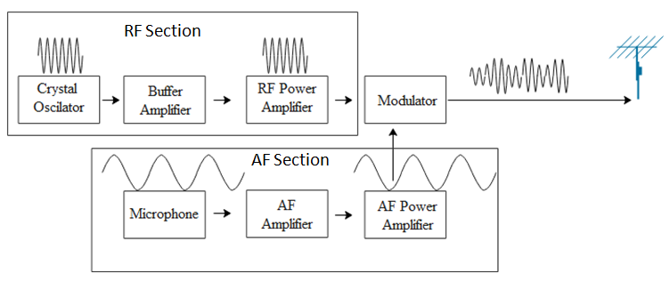
It is found that the height of the receiver antenna has to be at least one fourth of the wavelength of the signal. Hence we cannot use the audio signal directly as they have very large wavelengths and for that purpose we would require a huge antenna. Hence, this signal is superposed with a signal of high frequency such that the amplitude of the signals remains the same but wavelength of the signal is reduced. This process is called amplitude modulation. Given below is a block diagram for Amplitude Modulated (AM)radio transmitter.
Note:
In the above block diagram we can see that the signal is generated through the microphone. The magnitude of energy of the signal is very poor and hence, it is fed to the AF amplifier. This signal is further powered up by the AF power amplifier and sent to the modulator. The modulator is the place where the superposition of the carrier wave and the signal generated takes place. The crystal oscillator generates the high frequency carrier wave which is sent to the buffer which isolates the RF power amplifier keeping the frequency of the crystal controlled oscillator constant. Further the modulator mixes the carrier wave and the AF signal, which is fed to the antenna for transmission.
Formula used:
$U=-\dfrac{GMm}{r}$
$K=\dfrac{1}{2}m{{v}_{0}}^{2}$
Complete step by step answer:
To begin with let us first understand what do we mean by modulation.
It is found that the height of the receiver antenna has to be at least one fourth of the wavelength of the signal. Hence we cannot use the audio signal directly as they have very large wavelengths and for that purpose we would require a huge antenna. Hence, this signal is superposed with a signal of high frequency such that the amplitude of the signals remains the same but wavelength of the signal is reduced. This process is called amplitude modulation. Given below is a block diagram for Amplitude Modulated (AM)radio transmitter.
Note:
In the above block diagram we can see that the signal is generated through the microphone. The magnitude of energy of the signal is very poor and hence, it is fed to the AF amplifier. This signal is further powered up by the AF power amplifier and sent to the modulator. The modulator is the place where the superposition of the carrier wave and the signal generated takes place. The crystal oscillator generates the high frequency carrier wave which is sent to the buffer which isolates the RF power amplifier keeping the frequency of the crystal controlled oscillator constant. Further the modulator mixes the carrier wave and the AF signal, which is fed to the antenna for transmission.
Recently Updated Pages
Basicity of sulphurous acid and sulphuric acid are
Master Class 12 Economics: Engaging Questions & Answers for Success
Master Class 12 Biology: Engaging Questions & Answers for Success
Master Class 11 English: Engaging Questions & Answers for Success
Master Class 11 Physics: Engaging Questions & Answers for Success
Master Class 11 Computer Science: Engaging Questions & Answers for Success
Trending doubts
Draw a labelled sketch of the human eye class 12 physics CBSE
The chemical formula of tear gas is A CO Cl 2 B C 10 class 12 chemistry CBSE
Draw ray diagrams each showing i myopic eye and ii class 12 physics CBSE
Which are the Top 10 Largest Countries of the World?
Differentiate between homogeneous and heterogeneous class 12 chemistry CBSE
Which is the correct genotypic ratio of mendel dihybrid class 12 biology CBSE