


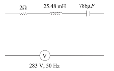
A sinusoidal voltage of peak value 283V and frequency 50Hz is applied to a series LCR circuit in which $R = 3\Omega $, $L = 25.48mH$, $C = 786\mu F$.
Find
(a) The impedance of the circuit
(b) The phase difference between the voltage across the source and the current.
(c) The power factors.
Answer
600.6k+ views
Hint: This is a formula-based question. In this question, we have to find three things impedance of the circuit, phase difference, and power factors. The power factor of the LCR circuit can be defined as the ratio of resistance to the total impedance of the circuit. The total impedance can be denoted by (Z) and they consist of the magnitude of the phasor sum of resistance, inductive resistance, and capacitive resistance. At resonance, the inductive and capacitive resistances are equal.
Complete answer:
The formula used in this question are,
Power factor (p.f) =\[\dfrac{{\operatorname{Re} sis\tan ce(R)}}{{TotalImpedance\left( Z \right)}}\]
Total impedance (Z)=$\sqrt {\left( {\mathop R\nolimits^2 } \right) + \mathop {\left( {\mathop X\nolimits_C - \mathop X\nolimits_L } \right)}\nolimits^2 } $
Where $\mathop X\nolimits_C = $capacitive resistance $ = \dfrac{1}{{\omega c}}$
$\mathop X\nolimits_L $= inductive resistance =$\omega L$
Where $\omega = 2\pi f$
$f $ is the frequency of AC source
$C$ is capacitive circuit
$L$ is inductive circuit
The power factor can be defined as the ratio of resistance to the total impedance of the circuit The total impedance can consist of the inductive resistance, capacitive resistance, and the magnitude of the phasor sum of the resistance.
The power factor can be measured by the fraction of total power that can be used up or dissipated by a load resistor. The capacitor and inductor do not dissipate power.
If the power factor will be higher than energy efficiency will be better as a result greater fraction of the power is available for utilization.
At resonance, the frequency is
$\mathop X\nolimits_C = \mathop X\nolimits_L $
Firstly, we find the Angular Frequency of the AC signal
$\omega = 2\pi \nu $
$ \Rightarrow \omega = 2\pi \left( {50} \right) = 100\pi $
Then the capacitive resistance, $\mathop X\nolimits_C = \dfrac{1}{{\omega c}}$
$ \Rightarrow \mathop X\nolimits_C = \dfrac{1}{{100\pi \times 786 \times \mathop {10}\nolimits^{ - 6} }} = 4\Omega $
Then the inductive reactance is = $\mathop X\nolimits_L = \omega L$
$ \Rightarrow \mathop X\nolimits_L = 100\pi \times \left( {24.48 \times \mathop {10}\nolimits^{ - 3} } \right) = 8\Omega $
(a) The impedance of the circuit:
Total impedance (Z)=$\sqrt {\left( {\mathop R\nolimits^2 } \right) + \mathop {\left( {\mathop X\nolimits_C - \mathop X\nolimits_L } \right)}\nolimits^2 } $
$ \Rightarrow Z = \sqrt {{3^2} + {{\left( {8 - 4} \right)}^2}} = 5\Omega $
(b) The phase difference between the voltage across the source and the current:
Phase difference\[\left( \phi \right) = \mathop {\tan }\nolimits^{ - 1} \left( {\dfrac{{\mathop X\nolimits_L - \mathop X\nolimits_C }}{R}} \right)\]
On substituting the corresponding values, we get
$ \Rightarrow \phi = \mathop {\tan }\nolimits^{ - 1} \left( {\dfrac{{8 - 4}}{3}} \right) = \mathop {\tan }\nolimits^{ - 1} \left( {\dfrac{4}{3}} \right)$
$ \Rightarrow \phi = 53.13^\circ $
(c) The power factor:
Power factor is denoted by cos $\phi $
So, power factor$ = \cos \phi = \cos 53.13^\circ $
Power factor= 0.6
$\therefore$ (a) Total impedance is $Z = \sqrt {{3^2} + {{\left( {8 - 4} \right)}^2}} = 5\Omega $
(b)The phase difference between the voltage across the source and the current is $\phi = 53.13^\circ $.
(c) Power factor is 0.6
Note:
At the stage of resonance, the LCR circuit behaves like a purely resistive circuit and the effects of the inductor and capacitor will cancel out each other. This circuit is the most efficient circuit in the operations. In these types of questions, firstly we have to remember all the formulas used and understand the meaning of RMS value and the terms such as impedance and reactance, then this type of question will be solved easily.
Recently Updated Pages
Basicity of sulphurous acid and sulphuric acid are
Master Class 12 English: Engaging Questions & Answers for Success
Master Class 12 Social Science: Engaging Questions & Answers for Success
Master Class 12 Maths: Engaging Questions & Answers for Success
Master Class 12 Economics: Engaging Questions & Answers for Success
Master Class 12 Physics: Engaging Questions & Answers for Success
Trending doubts
Draw a labelled sketch of the human eye class 12 physics CBSE
Which are the Top 10 Largest Countries of the World?
Draw ray diagrams each showing i myopic eye and ii class 12 physics CBSE
Giving reasons state the signs positive or negative class 12 physics CBSE
Explain esterification reaction with the help of a class 12 chemistry CBSE
What is defined as a solenoid Depict a diagram with class 12 physics CBSE