


Nodal Analysis: An Introduction
Node voltages are used as the circuit variables in the nodal analysis, offering a general procedure for studying circuits. The Node-Voltage Method is an alternative name for nodal analysis. The characteristics of nodal analysis include:
On the use of Kirchhoff's Current Law (KCL), nodal analysis is utilised
There will be "n-1" simultaneous equations to solve with "n" nodes
All of the node voltages can be found by solving 'n-1' equations
The number of possible nodal equations is equal to the number of non-reference nodes.
Keep reading through the following content to learn more about nodal analysis, types of nodes, examples, solving circuits using nodal analysis and more.
Kirchhoff’s Current Law
A technique for figuring out the branch currents in a circuit is termed nodal analysis. One of the nodes is chosen to serve as the reference node in this method. All the circuit's node potentials are calculated in relation to this reference node.
Kirchhoff's Current Law (KCL) asserts that "the algebraic sum of incoming currents and outgoing currents at a node is equal to zero," and serves as the foundation for the nodal analysis.
\[\begin{array}{l}\sum {\mathop I\nolimits_{incoming} + } \mathop I\nolimits_{outgoing} = 0\\\end{array}\]
Node: In a network, a node is a location where two or more circuit elements converge.
Junction: Junction is the place where three or more circuit elements come together. We must locate the potentials at the junction points rather than the nodes in the nodal analysis. There are fewer independent node-pair equations required than there are junctions in the network. In other words, if there are "n" independent node equations and "j" junctions, then:
\[n = j - 1\]
Types of Nodes
Non-Reference Node: It has a fixed node voltage.
Reference Node: It serves as a point of reference for all other nodes in the network.
Reference Node Types
Chassis Ground: This kind of reference node serves as a common node for multiple circuits.
Earth Ground: This type of reference node is known as Earth Ground when earth potential is utilised as a reference in any circuit.
Step-by-step Procedures
To resolve nodal analysis in an electrical circuit or network, follow these nodal analysis steps below:
Recognise the primary nodes in Step 1 and choose one of them to serve as the reference node. Thus, this node is handled the same as the ground.
Mark all the primary node’s voltages with respect to the ground terminal in Step 2, excluding the reference node.
Write nodal equations in Step 3 at each of the primary nodes aside from the reference node. You can arrive at this equation by first applying KCL and then Ohm's law.
We must resolve the nodal equations we obtained in Step 3 to obtain the node voltages in Step 4.
Difference Between Mesh and Nodal Analysis
In contrast to mesh analysis, which uses current values in a specific branch of a circuit, nodal analysis of an electrical network allows for the observation of voltages at a given branch. Mesh analysis is one type of technique used in the electrical network to solve planar circuits, specifically for the currents at any branch. Without putting any wires in contact with one another, these circuits can be sketched on a flat surface. Any circuit employs a more all-encompassing technique called loop analysis.
The KCL (Kirchhoff's Current Law) application is necessary for nodal analysis. The "n-1" instantaneous equations are required to solve n nodes. These equations can be solved to obtain all the node voltages. The number of acquirable nodal non-reference is equal to the number of reference nodes.
Solving of Circuit Using Nodal Analysis
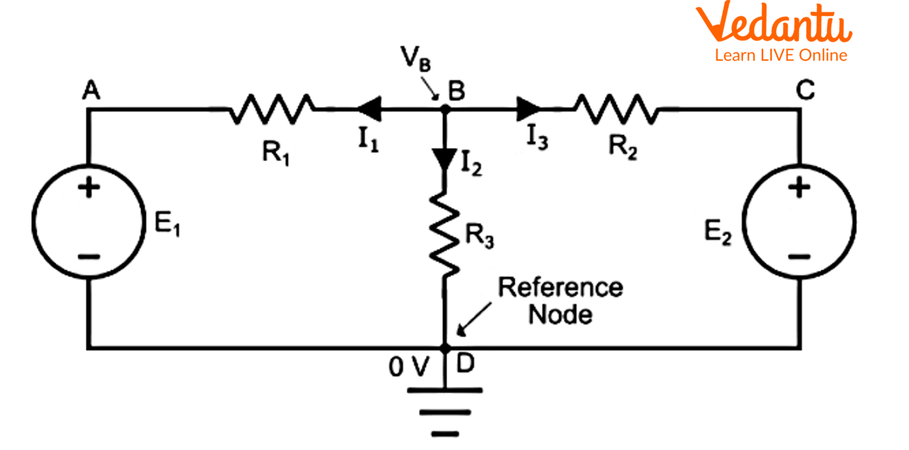
Look at the circuit below named Figure 1. A B, C, and D are the four nodes in the circuit, and nodes B and D are the junction points, with node D serving as the reference node.
Nodal analysis problems for an explanation of the mathematical solution.
Hence, If node B has a higher voltage \[\mathop V\nolimits_B \] than any of the other nodes in the circuit.
By putting KCL on node B, we get,
\[\mathop I\nolimits_1 + \mathop I\nolimits_2 + \mathop I\nolimits_3 = 0............(1)\]
The branch currents are now determined by Ohm's law to be,
\[\mathop I\nolimits_1 = \dfrac{{\mathop V\nolimits_B - \mathop E\nolimits_1 - 0}}{{\mathop R\nolimits_1 }} = \dfrac{{\mathop V\nolimits_B - \mathop E\nolimits_1 }}{{\mathop R\nolimits_1 }}\]
\[\mathop I\nolimits_3 = \dfrac{{\mathop V\nolimits_B - \mathop E\nolimits_2 - 0}}{{\mathop R\nolimits_2 }} = \dfrac{{\mathop V\nolimits_B - \mathop E\nolimits_2 }}{{\mathop R\nolimits_2 }}\]
${I_2} = \dfrac{V_B}{R_3}$
In equation (1), we obtain by substituting the values of \[\mathop I\nolimits_1 \], \[\mathop I\nolimits_2 \], and \[\mathop I\nolimits_3 \].
\[\dfrac{{\mathop V\nolimits_B - \mathop E\nolimits_1 }}{{\mathop R\nolimits_1 }} + \dfrac{{\mathop V\nolimits_B - \mathop E\nolimits_2 }}{{\mathop R\nolimits_2 }} + \dfrac{{\mathop V\nolimits_B }}{{\mathop R\nolimits_3 }} = 0...........(2)\]
The equation can be solved to determine the voltage \[\mathop V\nolimits_B \] at node B. (2). Since the resistance values, \[\mathop E\nolimits_1 \], and \[\mathop E\nolimits_2 \] values are known. As a result, we can calculate the branch current values.
Nodal Analysis Examples
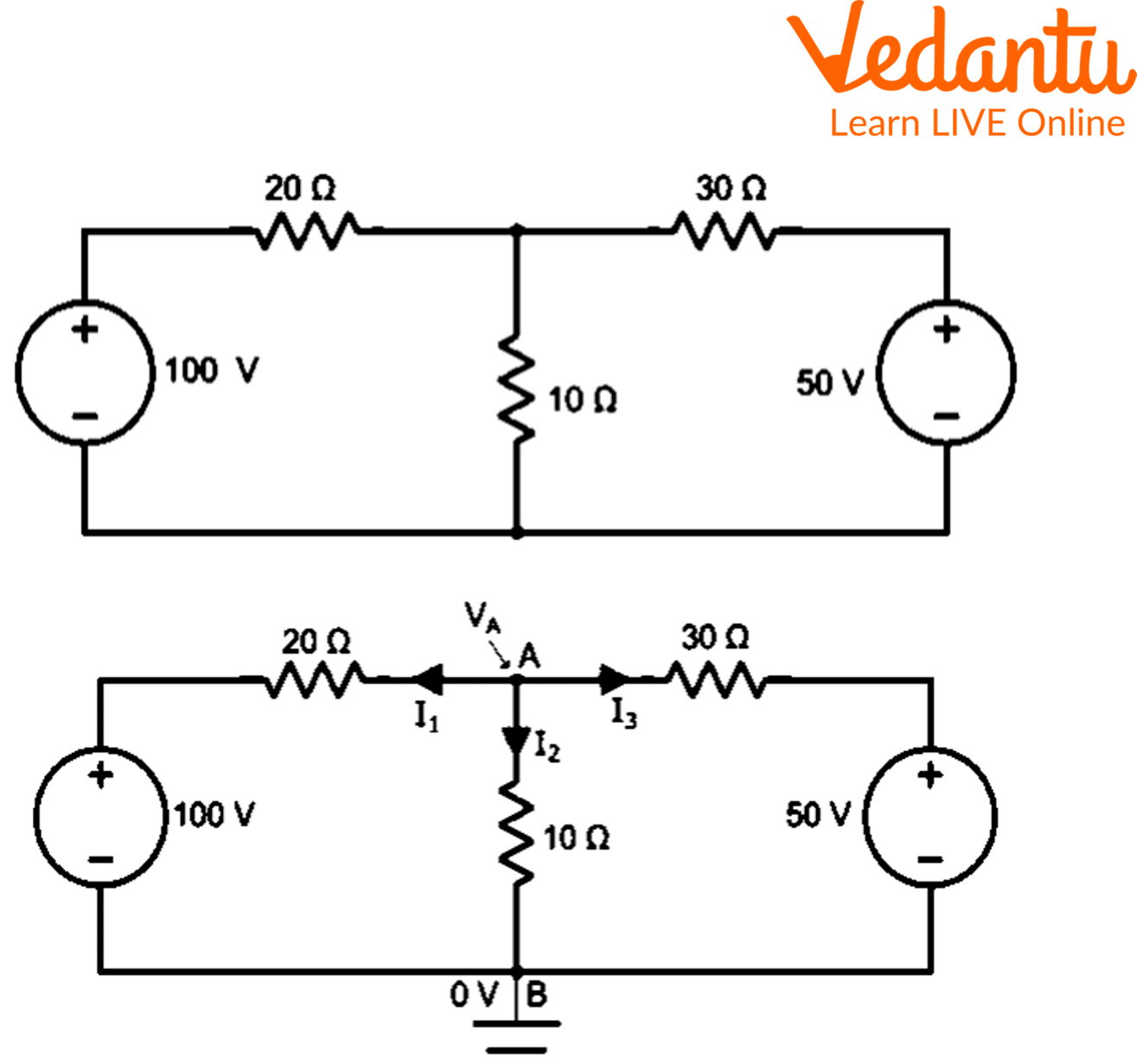
By using nodal analysis, determine the currents in the various circuit branches shown in the accompanying Figure 2.
Nodal Analysis Examples
As illustrated in the circuit schematic, indicate the currents in the various branches. The true direction of the current is the opposite of the assumed direction if the value of any current in the solution turns out to be negative. As the reference node, use point B. Thus,
\[\mathop I\nolimits_1 + \mathop I\nolimits_2 + \mathop I\nolimits_3 = 0............(1)\]
Using Ohm’s law,
\[\mathop I\nolimits_1 = \dfrac{{\mathop V\nolimits_A - 100}}{{20}}\]
\[\mathop I\nolimits_2 = \dfrac{{\mathop V\nolimits_A }}{{10}}\]
And
\[\mathop I\nolimits_3 = \dfrac{{\mathop V\nolimits_A - 50}}{{30}}\]
\[\dfrac{{\mathop V\nolimits_A - 100}}{{20}} + \dfrac{{\mathop V\nolimits_A - 50}}{{30}} + \dfrac{{\mathop V\nolimits_A }}{{10}} = 0\]
\[\dfrac{{3(\mathop V\nolimits_A - 100)}}{{60}} + \dfrac{{2(\mathop V\nolimits_A - 50)}}{{60}} + \dfrac{{6\mathop V\nolimits_A }}{{60}} = 0\]
\[\mathop {3V}\nolimits_A - 300 + \mathop {6V}\nolimits_A + \mathop {2V}\nolimits_A - 100 = 0\]
\[\mathop {11V}\nolimits_A = 400\]
\[\mathop V\nolimits_A = \dfrac{{400}}{{11}} = 36.36V\]
Current \[\mathop I\nolimits_1 = \dfrac{{\mathop V\nolimits_A - 100}}{{20}} = \dfrac{{36.36 - 100}}{{20}} = - 3.182V\]
Current \[\mathop I\nolimits_2 = \dfrac{{\mathop V\nolimits_A }}{{20}} = \dfrac{{36.36}}{{20}} = 3.636V\]
Current \[\mathop I\nolimits_3 = \dfrac{{\mathop V\nolimits_A - 50}}{{30}} = \dfrac{{36.36 - 50}}{{30}} = - 0.455V\]
The fact that currents have a negative sign indicates that their real directions are different from what was previously supposed.
Conclusion
This was all about a general overview of nodal analysis. When the circuit diagram doesn't show any conductor lane crossings, nodal analysis can be applied for circuit analysis prominently and uses Kirchhoff's Current Law & node equations to solve voltage values within the circuit. When the voltage at the ground terminal is equal to 0 volts, this nodal analysis can be used to determine the voltage at each node with respect to a reference node that is typically known as ground.
FAQs on Nodal Analysis: A Detailed Study
1. What is nodal analysis and why is it important in solving electrical circuits as per the CBSE 2025–26 Physics syllabus?
Nodal analysis is a systematic method used to determine the voltage at different nodes in an electrical circuit by applying Kirchhoff's Current Law (KCL). It is crucial because it simplifies complex circuit calculations, allowing students to analyze multi-node networks efficiently by reducing the number of equations to "n-1" for "n" nodes. This method helps build a strong conceptual foundation for exams and practical applications.
2. How do you select a reference node in the nodal analysis method?
To select a reference node in nodal analysis, choose the node with the most connections or branches. This node is assigned a voltage of zero (ground) and is used as the basis for measuring all other node voltages in the circuit. The choice of reference node does not affect the final answers but can simplify equations.
3. Outline the step-by-step procedure to apply nodal analysis for a circuit in board examinations.
Follow these steps:
- Identify all key nodes and select a reference node (ground).
- Label all node voltages with respect to the reference node.
- Apply KCL at every non-reference node to set up equations.
- Express each branch current in terms of node voltages using Ohm’s Law.
- Solve the simultaneous equations to determine all node voltages.
4. What is the difference between nodal analysis and mesh analysis, and when should each be used?
Nodal analysis focuses on finding node voltages using KCL, best applied to circuits with numerous nodes and fewer loops. Mesh analysis uses Kirchhoff's Voltage Law (KVL) to find loop currents and works well for planar circuits with fewer loops than nodes. Choose nodal for voltage analysis and mesh for current calculations in single-plane circuits.
5. In a circuit with 8 nodes, how many independent nodal equations must students write for CBSE board exams?
For a circuit with 8 nodes, you must write 7 independent nodal equations since one node is always chosen as the reference and doesn’t require an equation.
6. Why is Kirchhoff’s Current Law fundamental to the nodal analysis method?
Kirchhoff’s Current Law (KCL) is fundamental because it states that the algebraic sum of currents entering and leaving any node is zero. This principle forms the mathematical foundation for setting up the equations used in nodal analysis, ensuring charge conservation at every node within the network.
7. What are non-reference and reference nodes, and how do they affect circuit analysis?
A reference node (often ground) is assigned zero voltage and serves as the baseline for all measurements. Non-reference nodes are all other nodes where voltages are unknown and need to be determined. Setting the reference node simplifies the equations and comparisons of voltages throughout the circuit.
8. How does a negative current value in nodal analysis solutions impact interpretation during board exams?
A negative current value indicates that the actual direction of current is opposite to the initially assumed direction in your calculations. This understanding is essential for correctly drawing current directions and justifying answers as per CBSE evaluation criteria.
9. Can nodal analysis be applied to circuits with voltage and current sources, and how should students handle such cases in exams?
Nodal analysis can be applied to circuits with both voltage and current sources. For current sources, include their values directly in the node equations. For voltage sources between two non-reference nodes, use the supernode technique to combine the two nodes and apply KCL to the entire supernode.
10. What common mistakes should students avoid while performing nodal analysis in Physics board exams?
Students should avoid:
- Incorrectly choosing the reference node.
- Forgetting to apply KCL at all non-reference nodes.
- Errors in applying Ohm's Law for branch currents.
- Misinterpreting negative current or voltage values.
- Missing or extra equations beyond 'n-1' for 'n' nodes.
11. Why does nodal analysis typically result in fewer equations than the number of nodes in a network?
This occurs because one node is always chosen as the reference (ground) node and its voltage is defined as zero. Thus, only 'n-1' node equations are needed for 'n' total nodes, streamlining the solution process as emphasised in the CBSE curriculum.
12. How can nodal analysis be linked to real-life electrical or electronics applications beyond school exams?
Nodal analysis is widely used in designing and analyzing electrical circuits in engineering, from power distribution networks to electronic devices. Understanding this technique equips students to tackle practical problems in higher studies and various technology-driven industries.