


What is Half Wave Rectifier? An Introduction
A rectifier uses one or more P-N junction diodes to convert an alternating current (AC) to a direct current (DC). DC voltage is created by half wave rectifiers from AC voltage. In a half wave rectifier circuit, the transformation is carried out by a single diode. An AC voltage waveform can only travel in one half cycle of the input voltage in a half wave rectifier, and blocks the other half of the input voltage.
Rectifier
The domestic supply in our nation has a voltage variation of 220 V (RMS) at a frequency of 50 Hz. As DC voltage is needed to run the majority of electronic equipment so the main power supply's AC voltage must be converted to DC voltage hence a rectifier that uses one or more P-N junction diodes is used to change an alternating current (AC) into a direct current (DC).
The junction diode used in the rectifier has the ability to provide low resistance to the current passing through it when it is forward biased and high resistance to the current passing through it when it is reverse biased.
Half Wave Rectifier
The most basic type of rectifier is a half wave rectifier, which just needs one diode to be built into a circuit. A single diode coupled in series with a load resistor is exposed to an alternating voltage in a half wave rectifier circuit.
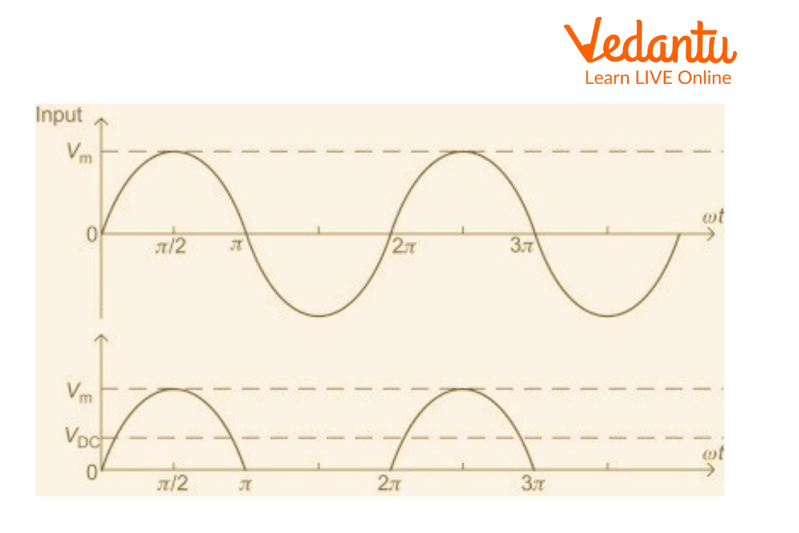
Waveform of Half Wave Rectifier
A full wave of an AC signal is made up of two equal positive and negative parts. Only one-half of the input AC cycle is passed by the PN junction diode to conduct electricity. When the diode is forward-based during a positive half cycle, it conducts and transfers the half wave. As the diode has little resistance in forward bias so the load resistor R experiences high current flow. As output voltage V grows across R, the half wave is transferred. When a diode is reverse biased during a negative half cycle, it does not conduct, Therefore, it provides no output (V=0). The circuit is known as a half wave rectifier because the output only has +ve half cycles or unidirectional half waves.
Half Wave Rectifier Diagram and Parameters
High Ac voltage is given to the primary side of the step down transformer. Secondary low voltage is provided to the diode. During the positive half cycle of the AC voltage, the diode is forward biased, and during the negative half cycle, it is reverse biased.
The waveform of the final output voltage is depicted in the figure below:
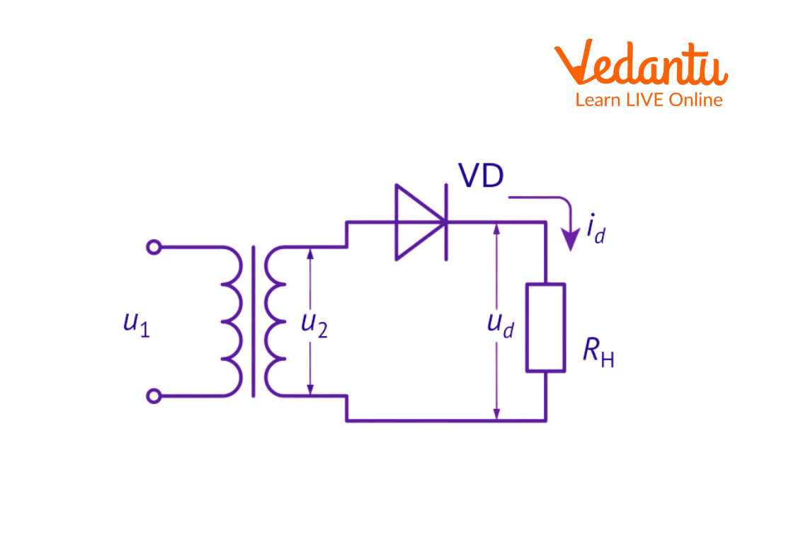
Half Wave Circuit
There are a few advantages of half wave rectifiers such as simple circuits, low cost, very easy to use, can be constructed easily, requires very few components, and so on. It has a 40.6% maximum efficiency. The half wave rectifier is very helpful in reducing noise.
Ripple Factor of Half Wave Rectifier
How well a half wave rectifier can change AC voltage into DC voltage is determined by the ripple factor. The formula below can be used to calculate the ripple factor,
\[\gamma = \sqrt {{{\left( {\dfrac{{{V_{rms}}}}{{{V_{dc}}}}} \right)}^2}} - 1\]
Ripple factor for the Half wave rectifier is 1.21.
Efficiency of Half Wave Rectifier
The ratio of the DC power output to the AC power input is the measure of a half wave rectifier's efficiency. The following is the half wave rectifier efficiency formula,
\[\eta = \dfrac{{{P_{dc}}}}{{{P_{ac}}}}\]
The maximum efficiency of the half wave rectifier is 40.6%.
RMS Value
The half wave rectifier RMS value is given by
RMS = Max. Value/2
VRMS=Vm/2
Interesting Facts
In the mosquito repellent, half wave rectifiers are used to form the fumes out of the lead.
They serve the aim of signal demodulation.
They are employed in applications for rectification.
They serve applications involving pulse-generating circuits.
Solved Problems
1. If 100 watts AC power is applied to the input of the half wave rectifier and obtained dc power is 40 watts, calculate the rectification efficiency.
Sol.
For the half wave rectifier, the rectification efficiency is given by,
\[{\rm{Rectification efficiency = }}\dfrac{{D{C_{out}}Power}}{{A{C_{in}}Power}}\]
\[\eta = \dfrac{{{P_{dc}}}}{{{P_{ac}}}}\]
\[\eta = \dfrac{{40}}{{100}}\]
\[\eta = 0.4\]
% \[\eta = 40\% \] (Convert to percentage)
2. If the internal resistance of the diode is 10 W and load resistance is 1000 W for half wave rectifiers, calculate the rectification efficiency. Take Irms=24.75 mA and Idc=15.76 mA.
Sol.
Here, internal resistance = Rd = 10 W
Load resistance = RL = 1000 W
Irms = 24.75 mA
Idc = 15.76 mA
We need to find Pdc and Pac for calculating the rectification efficiency.
Now,
\[{P_{ac}} = {({I_{rms}})^2}({R_d} + {R_L})\]
Putting the values and converting mA to A for Pac,
\[{P_{ac}} = {(24.75 \times {10^{ - 3}})^2}(10 + 1000)\]
\[{P_{ac}} = 0.618{\rm{ Watts}}\]
For Pdc,
\[{P_{dc}} = {({I_{dc}})^2}({R_L})\]
\[{P_{dc}} = {(15.76 \times {10^{ - 3}})^2}(1000)\]
\[{P_{dc}} = 0.248{\rm{ Watts}}\]
We know the rectification efficiency of half wave rectifier is,
\[\eta = \dfrac{{{P_{dc}}}}{{{P_{ac}}}}\]
\[\eta = \dfrac{{0.248}}{{0.618}}\]
\[\eta = \dfrac{{0.248}}{{0.618}} \times 100{\rm{ (convert to percentage)}}\]
\[\eta = 40.12\% \]
Summary
Half wave rectifier can be defined as a rectifier that allows only one half-cycle of an AC voltage waveform to pass, and blocks the other half-cycle. Half wave rectifiers are used to convert AC voltages to DC voltages. Half wave rectifiers require only a single diode to construct.
FAQs on Half Wave Rectifier
1. What is a half-wave rectifier and what is its main purpose in an electronic circuit?
A half-wave rectifier is an electronic circuit that converts an alternating current (AC) input into a direct current (DC) output. Its primary purpose is to allow current to flow during only one half of the AC cycle (either the positive or negative half) while blocking the other. This process, known as rectification, is a fundamental step in creating DC power supplies from an AC source.
2. How does a half-wave rectifier work during the positive and negative cycles of an AC input?
The working principle of a half-wave rectifier relies on a single p-n junction diode:
During the positive half-cycle of the AC input, the diode becomes forward-biased. It acts like a closed switch, allowing current to pass through to the load resistor.
During the negative half-cycle, the diode becomes reverse-biased. It acts like an open switch, blocking the flow of current. As a result, no output is produced during this half of the cycle.
3. What are the key differences between a half-wave and a full-wave rectifier?
The main differences between half-wave and full-wave rectifiers are:
AC Cycle Usage: A half-wave rectifier uses only one half-cycle of the AC input, while a full-wave rectifier utilizes both half-cycles.
Efficiency: The maximum theoretical efficiency of a half-wave rectifier is low, around 40.6%, whereas a full-wave rectifier is twice as efficient at about 81.2%.
Components: A half-wave rectifier requires only one diode. A full-wave rectifier needs either two diodes (with a center-tapped transformer) or four diodes (in a bridge configuration).
Output Smoothness: The output of a half-wave rectifier is more pulsating (higher ripple factor), while a full-wave rectifier produces a smoother, more continuous DC output.
4. What type of transformer is used in a half-wave rectifier circuit and why is it important?
A step-down transformer is typically used in a half-wave rectifier circuit. Its importance is twofold: first, it reduces the high voltage from the AC mains (e.g., 220V) to a much lower, safer voltage required by the diode and the load. Second, it provides electrical isolation between the high-voltage power line and the electronic circuit, which is a crucial safety feature.
5. Why is the output of a half-wave rectifier called a pulsating DC and not a pure DC?
The output is called pulsating DC because it is not a steady, constant voltage like that from a battery (which is pure DC). Since the rectifier only passes one half of the AC wave and blocks the other, the output consists of a series of positive pulses separated by gaps of zero voltage. This unidirectional but varying voltage is not constant, hence it 'pulsates'.
6. What are some practical examples and applications of a half-wave rectifier?
Due to its simplicity and low cost, a half-wave rectifier is used in low-power applications where a high-quality DC output is not critical. Common examples include:
Simple power supplies for low-cost electronics.
Circuits for soldering irons.
Mosquito repellent machines to heat the fumigation mat.
AM radio circuits as a signal demodulator.
7. Why is the efficiency of a half-wave rectifier so low (only 40.6%)?
The efficiency of a half-wave rectifier is low because it completely wastes the energy from one half of the AC input cycle. During the blocked (negative) half-cycle, no power is delivered to the load. This means that for half of the time, the circuit is not performing any work, which significantly reduces the overall ratio of output DC power to input AC power, leading to a maximum theoretical efficiency of only 40.6%.
8. How can the pulsating DC from a half-wave rectifier be smoothed, and what component is used?
The pulsating DC output can be smoothed by using a filter circuit. The simplest and most common filter component is a capacitor, connected in parallel with the load resistor. The capacitor charges up during the positive voltage pulse and then slowly discharges through the load during the zero-voltage gap. This action 'fills in the gaps' between pulses, significantly reducing the ripple and making the output voltage a much smoother, more stable DC.