


Two parallel wires $1 m$ apart carry currents of $1 A$ and $3 A$ respectively in opposite directions. The force per unit length acting between these two wires is:
A) \[6 \times \mathop {10}\nolimits^{ - 7} \] Nm-1 repulsive
B) \[6 \times \mathop {10}\nolimits^{ - 7} \] Nm-1 attractive
C) \[6 \times \mathop {10}\nolimits^{ - 5} \] Nm-1 repulsive
D) \[6 \times \mathop {10}\nolimits^{ - 5} \] Nm-1 attractive
Answer
249.3k+ views
Hint: The given problem is an example of two parallel conductors carrying currents are kept at a some distance apart from each-other then one conducting wire will have a force acting on it due to the presence of the other conducting wire and vice versa.
Complete step by step solution:
Step 1: Let us consider that the given two long straight conducting wires are \[\mathop P\nolimits_1 \mathop Q\nolimits_1 \] and \[\mathop P\nolimits_2 \mathop Q\nolimits_2 \] respectively that are kept at a distance \[r\] apart in the plane of paper. These wires are carrying the currents \[\mathop I\nolimits_1 \] and \[\mathop I\nolimits_2 \] respectively in the opposite direction.
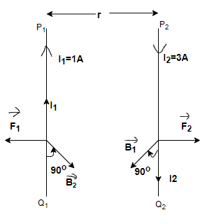
For this given problem the values of \[\mathop I\nolimits_1 \], \[\mathop I\nolimits_2 \], and \[r\] are given i.e.,
\[\mathop I\nolimits_1 = 1\] A and \[\mathop I\nolimits_2 = 3\] A and \[r = 1\] m.
The magnetic field is produced on each conducting wire at some point A due to the other conducting wire and because of that each wire having a magnetic field around it.
Since each conductor is in the magnetic field produced by the other, therefore, each conductor experiences a force of some amount and that amount is defined by the current flowing in the same conductor and magnetic field on that conductor due to the other conductor.
The magnetic field induction at a point A on the conductor \[\mathop P\nolimits_1 \mathop Q\nolimits_1 \] due to conductor \[\mathop P\nolimits_2 \mathop Q\nolimits_2 \] carrying the current \[\mathop I\nolimits_2 \] is given by the \[\mathop B\nolimits_2 \] and this \[\mathop B\nolimits_2 \] can be defined as given below –
\[\mathop B\nolimits_2 = \dfrac{{\mathop \mu \nolimits_0 }}{{4\pi }}\dfrac{{2\mathop I\nolimits_2 }}{r}\].....................(1)
According to the right-hand rule, the direction of \[\mathop B\nolimits_2 \] is perpendicular to the plane of paper, directed inward.
Similarly, the magnetic field induction at a point A on the conductor \[\mathop P\nolimits_2 \mathop Q\nolimits_2 \] due to conductor \[\mathop P\nolimits_1 \mathop Q\nolimits_1 \] carrying the current \[\mathop I\nolimits_1 \] is given by the \[\mathop B\nolimits_1 \] and this \[\mathop B\nolimits_1 \] can be defined as given below –
\[\mathop B\nolimits_1 = \dfrac{{\mathop \mu \nolimits_0 }}{{4\pi }}\dfrac{{2\mathop I\nolimits_1 }}{r}\].....................(2)
Step 2:
So, the force per unit length acting between these two wires can be calculate from the equation given below –
\[\dfrac{{\mathop F\nolimits_2 }}{l} = \mathop B\nolimits_1 \times \mathop I\nolimits_2 \] as we know that \[\mathop F\nolimits_2 = \mathop B\nolimits_1 \times \mathop I\nolimits_2 \times l\]
Or \[\dfrac{{\mathop F\nolimits_1 }}{l} = \mathop B\nolimits_2 \times \mathop I\nolimits_1 \] as we know that \[\mathop F\nolimits_1 = \mathop B\nolimits_2 \times \mathop I\nolimits_1 \times l\]
So, \[\dfrac{{\mathop F\nolimits_2 }}{l} = \dfrac{{\mathop \mu \nolimits_0 }}{{4\pi }}\dfrac{{2\mathop I\nolimits_1 \mathop I\nolimits_2 }}{r} = \dfrac{{\mathop F\nolimits_1 }}{l}\]
So, by substituting the values from above equations and \[\dfrac{{\mathop \mu \nolimits_0 }}{{4\pi }} = \mathop {10}\nolimits^{ - 7} \], \[l = 1\]m force per unit length can be calculated
\[\dfrac{{\mathop F\nolimits_2 }}{l} = \mathop {10}\nolimits^{ - 7} \times \dfrac{{2 \times 1 \times 3}}{1}\]
\[\dfrac{{\mathop F\nolimits_2 }}{l} = 6 \times \mathop {10}\nolimits^{ - 7} \] $N/m$ and as from the figure it can be seen that force is repulsive in nature. The direction of force can be determined by Fleming's Left-Hand Rule.
So, the option (A) is correct.
Note: The direction of magnetic field can be determined by the right-hand rule and it will be perpendicular to the plane of paper either inward or outward depending upon the direction of current flowing through the conductor.
The direction of force on the conductor can be given by the Fleming’s Left-Hand Rule which states that “If we stretch the first finger, the central finger and the thumb of left hand mutually perpendicular to each-other such that the first finger points to the direction of magnetic field, the central finger points to the direction of electric current (motion of the positive charge) then thumb represents the direction of force experienced by the charged particle”.
Complete step by step solution:
Step 1: Let us consider that the given two long straight conducting wires are \[\mathop P\nolimits_1 \mathop Q\nolimits_1 \] and \[\mathop P\nolimits_2 \mathop Q\nolimits_2 \] respectively that are kept at a distance \[r\] apart in the plane of paper. These wires are carrying the currents \[\mathop I\nolimits_1 \] and \[\mathop I\nolimits_2 \] respectively in the opposite direction.
For this given problem the values of \[\mathop I\nolimits_1 \], \[\mathop I\nolimits_2 \], and \[r\] are given i.e.,
\[\mathop I\nolimits_1 = 1\] A and \[\mathop I\nolimits_2 = 3\] A and \[r = 1\] m.
The magnetic field is produced on each conducting wire at some point A due to the other conducting wire and because of that each wire having a magnetic field around it.
Since each conductor is in the magnetic field produced by the other, therefore, each conductor experiences a force of some amount and that amount is defined by the current flowing in the same conductor and magnetic field on that conductor due to the other conductor.
The magnetic field induction at a point A on the conductor \[\mathop P\nolimits_1 \mathop Q\nolimits_1 \] due to conductor \[\mathop P\nolimits_2 \mathop Q\nolimits_2 \] carrying the current \[\mathop I\nolimits_2 \] is given by the \[\mathop B\nolimits_2 \] and this \[\mathop B\nolimits_2 \] can be defined as given below –
\[\mathop B\nolimits_2 = \dfrac{{\mathop \mu \nolimits_0 }}{{4\pi }}\dfrac{{2\mathop I\nolimits_2 }}{r}\].....................(1)
According to the right-hand rule, the direction of \[\mathop B\nolimits_2 \] is perpendicular to the plane of paper, directed inward.
Similarly, the magnetic field induction at a point A on the conductor \[\mathop P\nolimits_2 \mathop Q\nolimits_2 \] due to conductor \[\mathop P\nolimits_1 \mathop Q\nolimits_1 \] carrying the current \[\mathop I\nolimits_1 \] is given by the \[\mathop B\nolimits_1 \] and this \[\mathop B\nolimits_1 \] can be defined as given below –
\[\mathop B\nolimits_1 = \dfrac{{\mathop \mu \nolimits_0 }}{{4\pi }}\dfrac{{2\mathop I\nolimits_1 }}{r}\].....................(2)
Step 2:
So, the force per unit length acting between these two wires can be calculate from the equation given below –
\[\dfrac{{\mathop F\nolimits_2 }}{l} = \mathop B\nolimits_1 \times \mathop I\nolimits_2 \] as we know that \[\mathop F\nolimits_2 = \mathop B\nolimits_1 \times \mathop I\nolimits_2 \times l\]
Or \[\dfrac{{\mathop F\nolimits_1 }}{l} = \mathop B\nolimits_2 \times \mathop I\nolimits_1 \] as we know that \[\mathop F\nolimits_1 = \mathop B\nolimits_2 \times \mathop I\nolimits_1 \times l\]
So, \[\dfrac{{\mathop F\nolimits_2 }}{l} = \dfrac{{\mathop \mu \nolimits_0 }}{{4\pi }}\dfrac{{2\mathop I\nolimits_1 \mathop I\nolimits_2 }}{r} = \dfrac{{\mathop F\nolimits_1 }}{l}\]
So, by substituting the values from above equations and \[\dfrac{{\mathop \mu \nolimits_0 }}{{4\pi }} = \mathop {10}\nolimits^{ - 7} \], \[l = 1\]m force per unit length can be calculated
\[\dfrac{{\mathop F\nolimits_2 }}{l} = \mathop {10}\nolimits^{ - 7} \times \dfrac{{2 \times 1 \times 3}}{1}\]
\[\dfrac{{\mathop F\nolimits_2 }}{l} = 6 \times \mathop {10}\nolimits^{ - 7} \] $N/m$ and as from the figure it can be seen that force is repulsive in nature. The direction of force can be determined by Fleming's Left-Hand Rule.
So, the option (A) is correct.
Note: The direction of magnetic field can be determined by the right-hand rule and it will be perpendicular to the plane of paper either inward or outward depending upon the direction of current flowing through the conductor.
The direction of force on the conductor can be given by the Fleming’s Left-Hand Rule which states that “If we stretch the first finger, the central finger and the thumb of left hand mutually perpendicular to each-other such that the first finger points to the direction of magnetic field, the central finger points to the direction of electric current (motion of the positive charge) then thumb represents the direction of force experienced by the charged particle”.
Recently Updated Pages
JEE Isolation, Preparation and Properties of Non-metals Important Concepts and Tips for Exam Preparation
Isoelectronic Definition in Chemistry: Meaning, Examples & Trends
Ionisation Energy and Ionisation Potential Explained
Iodoform Reactions - Important Concepts and Tips for JEE
Introduction to Dimensions: Understanding the Basics
Instantaneous Velocity Explained: Formula, Examples & Graphs
Trending doubts
JEE Main 2026: Exam Dates, Session 2 Updates, City Slip, Admit Card & Latest News
Hybridisation in Chemistry – Concept, Types & Applications
JEE Main 2026 Application Login: Direct Link, Registration, Form Fill, and Steps
Understanding the Electric Field of a Uniformly Charged Ring
Derivation of Equation of Trajectory Explained for Students
JEE Main Marking Scheme 2026- Paper-Wise Marks Distribution and Negative Marking Details
Other Pages
CBSE Class 12 Physics Question Paper 2026: Download SET-wise PDF with Answer Key & Analysis
JEE Advanced Marks vs Ranks 2025: Understanding Category-wise Qualifying Marks and Previous Year Cut-offs
JEE Advanced 2026 - Exam Date (Released), Syllabus, Registration, Eligibility, Preparation, and More
JEE Advanced Weightage 2025 Chapter-Wise for Physics, Maths and Chemistry
Understanding the Angle of Deviation in a Prism
Understanding Centrifugal Force in Physics