


In the circuit shown in the figure, the current through ${R_2}$ is zero if ${R_4} = 2\Omega $ and ${R_3} = 4\Omega $. In this case:
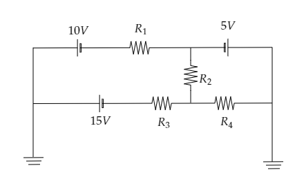
A) current through ${R_3}$ is $2{\text{A}}$
B) current through ${R_4}$ is ${\text{3A}}$
C) both A and B are correct
D) both A and B are wrong
Answer
256.2k+ views
Hint: Here it is mentioned that the resistance ${R_2}$ is zero. So we can redraw the given circuit diagram by replacing that resistor with a straight wire. Then we will obtain two circuits. The first circuit will comprise resistances ${R_1}$ and ${R_3}$ while the second circuit comprises the resistance ${R_4}$ . The current through the required resistors can then be determined by applying Ohm’s law to each circuit.
Formula used:
Ohm’s law given the current in a circuit as $I = \dfrac{V}{R}$ where $V$ is the potential difference across the circuit and $R$ is the resistance offered by the circuit.
Complete step by step solution:
Sketch the given circuit diagram and mark the junctions involved.
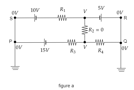
It is given that ${R_3} = 4\Omega $ and ${R_4} = 2\Omega $ .
From the above figure, we see that points P and Q are connected to ground so the potential at those points will be zero. Then the potential at points S and R will also be zero. The potential difference across the resistor ${R_2}$ will be $V$ since it is given that ${R_2} = 0$ .
Now we can replace ${R_2}$ by a straight wire so that we split the above circuit into two circuits. In the first circuit, the current will be ${i_1}$ and in the second circuit, the current will be ${i_2}$ . This is shown in the figure below.
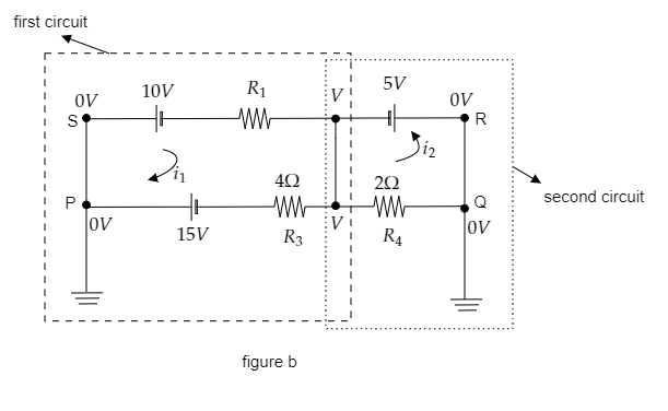
Using Ohm’s law, express the current in the second circuit.
In the second circuit, the potential difference is given by the emf of the cell i.e., $V = 5{\text{V}}$ .
The resistance offered by the circuit is given to be ${R_4} = 2\Omega $.
Then by Ohm’s law, the current through the second circuit is expressed as ${i_2} = \dfrac{V}{{{R_4}}} = \dfrac{5}{2} = 2.5{\text{A}}$.
So the current through ${R_4}$ will be $2.5{\text{A}}$ .
So options B and C are not correct.
Sketch the first circuit with the net EMF and the effective resistance to obtain the current through this circuit using Ohm’s law.
The two cells of emf $10{\text{V}}$ and $15{\text{V}}$ will give a net EMF of ${V_{net}} = 15 - 10 = 5{\text{V}}$ .
Also the two resistors ${R_1}$ and ${R_3}$ give an effective resistance of ${R_{eff}} = {R_1} + {R_3}$ .
This is sketched in the figure below.
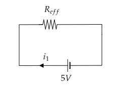
Then by Ohm’s law, the current in this circuit can be expressed as ${i_1} = \dfrac{{{V_{net}}}}{{{R_{eff}}}} = \dfrac{{{V_{net}}}}{{{R_1} + {R_3}}}$ ------- (1)
Now substituting for ${R_3} = 4\Omega $ , ${R_1} = 0$ and ${V_{net}} = 5{\text{V}}$ , then we get, ${i_1} = \dfrac{5}{{0 + 4}} = 1.25{\text{A}}$
The current through the circuit and the current through ${R_3}$ will be the same. So the current through ${R_3}$ is obtained to be $1.25{\text{A}}$ .
So option A is also incorrect and thus the correct option will be D.
Note: In figure b, the resistors ${R_1}$ and ${R_3}$ are connected in series so we have the effective resistance of the first circuit to be the sum of the two resistances. In a series connection, the current through the two resistors will be the same. Also, the cells in the first circuit are connected in series with their positive terminal connected together, so the net EMF will be the difference between the two EMFs.
Formula used:
Ohm’s law given the current in a circuit as $I = \dfrac{V}{R}$ where $V$ is the potential difference across the circuit and $R$ is the resistance offered by the circuit.
Complete step by step solution:
Sketch the given circuit diagram and mark the junctions involved.
It is given that ${R_3} = 4\Omega $ and ${R_4} = 2\Omega $ .
From the above figure, we see that points P and Q are connected to ground so the potential at those points will be zero. Then the potential at points S and R will also be zero. The potential difference across the resistor ${R_2}$ will be $V$ since it is given that ${R_2} = 0$ .
Now we can replace ${R_2}$ by a straight wire so that we split the above circuit into two circuits. In the first circuit, the current will be ${i_1}$ and in the second circuit, the current will be ${i_2}$ . This is shown in the figure below.
Using Ohm’s law, express the current in the second circuit.
In the second circuit, the potential difference is given by the emf of the cell i.e., $V = 5{\text{V}}$ .
The resistance offered by the circuit is given to be ${R_4} = 2\Omega $.
Then by Ohm’s law, the current through the second circuit is expressed as ${i_2} = \dfrac{V}{{{R_4}}} = \dfrac{5}{2} = 2.5{\text{A}}$.
So the current through ${R_4}$ will be $2.5{\text{A}}$ .
So options B and C are not correct.
Sketch the first circuit with the net EMF and the effective resistance to obtain the current through this circuit using Ohm’s law.
The two cells of emf $10{\text{V}}$ and $15{\text{V}}$ will give a net EMF of ${V_{net}} = 15 - 10 = 5{\text{V}}$ .
Also the two resistors ${R_1}$ and ${R_3}$ give an effective resistance of ${R_{eff}} = {R_1} + {R_3}$ .
This is sketched in the figure below.
Then by Ohm’s law, the current in this circuit can be expressed as ${i_1} = \dfrac{{{V_{net}}}}{{{R_{eff}}}} = \dfrac{{{V_{net}}}}{{{R_1} + {R_3}}}$ ------- (1)
Now substituting for ${R_3} = 4\Omega $ , ${R_1} = 0$ and ${V_{net}} = 5{\text{V}}$ , then we get, ${i_1} = \dfrac{5}{{0 + 4}} = 1.25{\text{A}}$
The current through the circuit and the current through ${R_3}$ will be the same. So the current through ${R_3}$ is obtained to be $1.25{\text{A}}$ .
So option A is also incorrect and thus the correct option will be D.
Note: In figure b, the resistors ${R_1}$ and ${R_3}$ are connected in series so we have the effective resistance of the first circuit to be the sum of the two resistances. In a series connection, the current through the two resistors will be the same. Also, the cells in the first circuit are connected in series with their positive terminal connected together, so the net EMF will be the difference between the two EMFs.
Recently Updated Pages
Electricity and Magnetism Explained: Key Concepts & Applications
JEE Energetics Important Concepts and Tips for Exam Preparation
JEE Isolation, Preparation and Properties of Non-metals Important Concepts and Tips for Exam Preparation
JEE Main Mock Test 2025-26: Electromagnetic Induction & Alternating Currents
JEE Main 2023 (February 1st Shift 1) Maths Question Paper with Answer Key
JEE Main 2023 (February 1st Shift 2) Maths Question Paper with Answer Key
Trending doubts
JEE Main 2026: Exam Dates, Session 2 Updates, City Slip, Admit Card & Latest News
JEE Main Participating Colleges 2026 - A Complete List of Top Colleges
JEE Main 2026 Application Login: Direct Link, Registration, Form Fill, and Steps
JEE Main Colleges 2026: Complete List of Participating Institutes
JEE Main Marking Scheme 2026- Paper-Wise Marks Distribution and Negative Marking Details
Hybridisation in Chemistry – Concept, Types & Applications
Other Pages
CBSE Class 12 Physics Question Paper 2026: Download SET-wise PDF with Answer Key & Analysis
JEE Advanced 2026 - Exam Date (Released), Syllabus, Registration, Eligibility, Preparation, and More
JEE Advanced Marks vs Ranks 2025: Understanding Category-wise Qualifying Marks and Previous Year Cut-offs
JEE Advanced Weightage 2025 Chapter-Wise for Physics, Maths and Chemistry
Understanding the Electric Field of a Uniformly Charged Ring
Derivation of Equation of Trajectory Explained for Students