


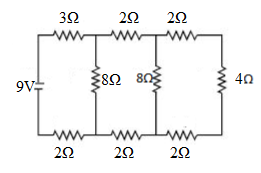
In circuit shown in figure the current through
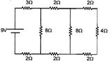
A. the \[3\Omega \] resistor is \[0.50A\]
B. the \[3\Omega \] resistor is \[0.25A\]
C .the \[4\Omega \] resistor is \[0.50A\]
D. the \[4\Omega \]resistor is \[0.25A\]
Answer
260.4k+ views
Hint: The resistor's voltage V in volts (V) divided by its resistance R in ohms (R) gives rise to the resistor's current I in amps (A): V is the voltage drop of the resistor, expressed in Volts (V). Voltage is sometimes represented by the letter E in Ohm's law.
Formula used:
Complete answer:
We have been provided in the question that the current through the circuit is,
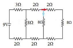
To begin, we will calculate the equivalent resistance of the resistors in the circle.
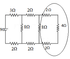
These resistances are connected in series. As a result, their equivalent resistance is equal to \[2\Omega + 4\Omega + 2\Omega = 8\Omega \] according to the formula. This equivalent resistor, together with the resistor in the box, yields an equivalent resistor of \[{\left( {\frac{1}{{8{\rm{\Omega }}}} + \frac{1}{{8{\rm{\Omega }}}}} \right)^{ - 1}} = 4{\rm{\Omega }}\]
This is depicted in the following figure.
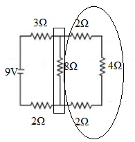
Repeating the process for the resistors in the circle and box, we get the equivalent resistance of the resistors in the circle as \[2\Omega + 4\Omega + 2\Omega = 8\Omega \], and the equivalent resistance of this and the resistor in the box as \[{\left( {\frac{1}{{8{\rm{\Omega }}}} + \frac{1}{{8{\rm{\Omega }}}}} \right)^{ - 1}} = 4{\rm{\Omega }}\].
This is depicted in the following figure.
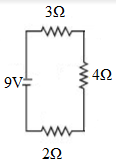
We can observe that the overall resistance in the circuit is
\[2\Omega + 4\Omega + 3\Omega = 9\Omega \]
As per Ohm's law, the current flowing through in this circuit will now be
\[V = IR\]
On solving for I, we can write as
\[I = \frac{V}{R}\]
Now, we have to substitute the value we get
\[ = \frac{{9V}}{{9{\rm{\Omega }}}}\]
On simplifying the above equation, we get
\[ = 1A\]
Returning to the original circuit, the resistance on both routes is equal, therefore the current divides equally once more.
This gives us the current through the \[3\] ohm resistor as \[1\] amp and the current through the 4 ohm resistor as \[0.25\] amp
As a result, the current will be divided equally.
Hence, the option B is correct
Note: Keep in mind that current does not always split evenly between the two branches of the circuit. It is determined by the amount of resistance between them. The current was equally distributed in this case because the resistance on the different branches of the circuit was equal.
Formula used:
Complete answer:
We have been provided in the question that the current through the circuit is,
To begin, we will calculate the equivalent resistance of the resistors in the circle.
These resistances are connected in series. As a result, their equivalent resistance is equal to \[2\Omega + 4\Omega + 2\Omega = 8\Omega \] according to the formula. This equivalent resistor, together with the resistor in the box, yields an equivalent resistor of \[{\left( {\frac{1}{{8{\rm{\Omega }}}} + \frac{1}{{8{\rm{\Omega }}}}} \right)^{ - 1}} = 4{\rm{\Omega }}\]
This is depicted in the following figure.
Repeating the process for the resistors in the circle and box, we get the equivalent resistance of the resistors in the circle as \[2\Omega + 4\Omega + 2\Omega = 8\Omega \], and the equivalent resistance of this and the resistor in the box as \[{\left( {\frac{1}{{8{\rm{\Omega }}}} + \frac{1}{{8{\rm{\Omega }}}}} \right)^{ - 1}} = 4{\rm{\Omega }}\].
This is depicted in the following figure.
We can observe that the overall resistance in the circuit is
\[2\Omega + 4\Omega + 3\Omega = 9\Omega \]
As per Ohm's law, the current flowing through in this circuit will now be
\[V = IR\]
On solving for I, we can write as
\[I = \frac{V}{R}\]
Now, we have to substitute the value we get
\[ = \frac{{9V}}{{9{\rm{\Omega }}}}\]
On simplifying the above equation, we get
\[ = 1A\]
Returning to the original circuit, the resistance on both routes is equal, therefore the current divides equally once more.
This gives us the current through the \[3\] ohm resistor as \[1\] amp and the current through the 4 ohm resistor as \[0.25\] amp
As a result, the current will be divided equally.
Hence, the option B is correct
Note: Keep in mind that current does not always split evenly between the two branches of the circuit. It is determined by the amount of resistance between them. The current was equally distributed in this case because the resistance on the different branches of the circuit was equal.
Recently Updated Pages
JEE Main Mock Test 2025-26: Electromagnetic Induction & Alternating Currents
JEE Main Mock Test 2025-26: Optics Chapter Practice Online
JEE Main 2025-26 Mock Test: Properties of Solids and Liquids
JEE Main Mock Test 2025-26: Dual Nature of Matter & Radiation
JEE Main 2025-26 Electromagnetic Waves Mock Test with Solutions
JEE Main 2025-26 Mock Test: Electronic Devices Chapter Practice
Trending doubts
JEE Main 2026: Exam Dates, Session 2 Updates, City Slip, Admit Card & Latest News
JEE Main Participating Colleges 2026 - A Complete List of Top Colleges
Hybridisation in Chemistry – Concept, Types & Applications
Understanding the Electric Field of a Uniformly Charged Ring
Derivation of Equation of Trajectory Explained for Students
Understanding Atomic Structure for Beginners
Other Pages
CBSE Class 12 Physics Question Paper 2026: Download SET-wise PDF with Answer Key & Analysis
JEE Advanced 2026 Notification Out with Exam Date, Registration (Extended), Syllabus and More
JEE Advanced Marks vs Ranks 2025: Understanding Category-wise Qualifying Marks and Previous Year Cut-offs
JEE Advanced Weightage Chapter Wise 2026 for Physics, Chemistry, and Mathematics
How to Convert a Galvanometer into an Ammeter or Voltmeter
Electron Gain Enthalpy and Electron Affinity Explained