


What is the coefficient of coupling for a transformer in which 4% of the total flux generated in the primary does not pass through the secondary?
A. 0.4
B. 4
C. 9.6
D. 0.96
Answer
270.9k+ views
Hint: We can find the coefficient of coupling for a transformer by dividing magnetic flux linked with secondary coil by magnetic flux linked with primary coil. According to the formula \[k=\dfrac{\text{Magnetic Flux linked with second coil}}{\text{Magnetic flux linked with first coil}}\], here k is the coefficient of coupling for a transformer. Value of k depends on the positions of the coil with respect to each other. Keep in mind that there is a loss of 4% of the flux in the primary coil which does not link to the secondary part.
Complete step-by-step answer:
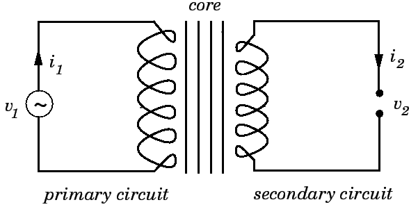
A transformer is based on the principle of conservation of flux. That is the flux in the primary side of the transformer is linked to the secondary side. Since, the number of turns of coils on both the sides differ, different values of currents and voltages are transformed to the secondary side, which is the main use of the instrument. Please refer to the figure.
In the above question it is mentioned that 4% of the total flux generated doesn’t pass through the secondary coil. So, the value of magnetic flux linked with the second coil will be 96% of the primary side.
Magnetic flux linked with the first coil will be 100%.
Coefficient of coupling, k, is given by the following relation:
\[k=\dfrac{\text{Magnetic Flux linked with second coil}}{\text{Magnetic flux linked with first coil}}\]
We can put these values into the formula as;
$k=\dfrac{96%}{100%}=0.96$
Thus, the answer will be option D.
Additional point:
1. There are two Faraday’s law regarding electromagnetic induction
a. First law - Whenever there is a change in the magnetic flux linked with an electric circuit, an induced emf is produced in the circuit and will be produced as long as change in magnetic field continues.
b. Second law – The induced emf will be equal to the negative of the change in magnetic flux with time given as;
$emf=-\dfrac{d\phi }{dt}$
Where a negative sign indicates that electric circuits resist change in magnetic flux linked with it.
$\phi $ represents the magnetic flux.
2. Transformer is the device that raises and lowers the AC circuit voltage through mutual induction.
Mutual induction – Transformer is made up of two coils wound on the same core. When AC passes through one coil, it generates changing magnetic flux. This changing magnetic flux passes through the secondary coil and induces AC current there.
Note: When current flows through one coil it produces flux; the whole flux may not link with the other coil coupled, and this is because of leakage flux by a fraction (k) known as coefficient of coupling.
The value of coefficient of coupling (k) depends on the positions of the secondary coil with respect to the primary coil and k’s value varies from 0 to 1.
k = 1, when flux produced by the primary coil completely links with the secondary coil.
k = 0, when flux produced by the primary coil doesn’t link with the secondary coil.
Complete step-by-step answer:
A transformer is based on the principle of conservation of flux. That is the flux in the primary side of the transformer is linked to the secondary side. Since, the number of turns of coils on both the sides differ, different values of currents and voltages are transformed to the secondary side, which is the main use of the instrument. Please refer to the figure.
In the above question it is mentioned that 4% of the total flux generated doesn’t pass through the secondary coil. So, the value of magnetic flux linked with the second coil will be 96% of the primary side.
Magnetic flux linked with the first coil will be 100%.
Coefficient of coupling, k, is given by the following relation:
\[k=\dfrac{\text{Magnetic Flux linked with second coil}}{\text{Magnetic flux linked with first coil}}\]
We can put these values into the formula as;
$k=\dfrac{96%}{100%}=0.96$
Thus, the answer will be option D.
Additional point:
1. There are two Faraday’s law regarding electromagnetic induction
a. First law - Whenever there is a change in the magnetic flux linked with an electric circuit, an induced emf is produced in the circuit and will be produced as long as change in magnetic field continues.
b. Second law – The induced emf will be equal to the negative of the change in magnetic flux with time given as;
$emf=-\dfrac{d\phi }{dt}$
Where a negative sign indicates that electric circuits resist change in magnetic flux linked with it.
$\phi $ represents the magnetic flux.
2. Transformer is the device that raises and lowers the AC circuit voltage through mutual induction.
Mutual induction – Transformer is made up of two coils wound on the same core. When AC passes through one coil, it generates changing magnetic flux. This changing magnetic flux passes through the secondary coil and induces AC current there.
Note: When current flows through one coil it produces flux; the whole flux may not link with the other coil coupled, and this is because of leakage flux by a fraction (k) known as coefficient of coupling.
The value of coefficient of coupling (k) depends on the positions of the secondary coil with respect to the primary coil and k’s value varies from 0 to 1.
k = 1, when flux produced by the primary coil completely links with the secondary coil.
k = 0, when flux produced by the primary coil doesn’t link with the secondary coil.
Recently Updated Pages
JoSAA Counselling 2026: JoSAA 2026 Mock Seat Allotment LIVE: Round 2 Result Released, Registration, Choice Filling and Ranks
JEE General Topics in Chemistry Important Concepts and Tips
JEE Extractive Metallurgy Important Concepts and Tips for Exam Preparation
JEE Atomic Structure and Chemical Bonding important Concepts and Tips
JEE Amino Acids and Peptides Important Concepts and Tips for Exam Preparation
Electricity and Magnetism Explained: Key Concepts & Applications
Trending doubts
JEE Main 2026: Exam Dates, Session 2 Updates, City Slip, Admit Card & Latest News
JEE Main Participating Colleges 2026 - A Complete List of Top Colleges
Understanding the Electric Field of a Uniformly Charged Ring
Understanding Atomic Structure for Beginners
Derivation of Equation of Trajectory Explained for Students
JEE Main Marking Scheme 2026- Paper-Wise Marks Distribution and Negative Marking Details
Other Pages
JEE Advanced 2026 Notification Out with Exam Date, Registration (Extended), Syllabus and More
JEE Advanced Percentile vs Marks 2026: JEE Main Cutoff, AIR & IIT Admission Guide
JEE Advanced Weightage Chapter Wise 2026 for Physics, Chemistry, and Mathematics
How to Convert a Galvanometer into an Ammeter or Voltmeter
Electron Gain Enthalpy and Electron Affinity Explained
Understanding Electromagnetic Waves and Their Importance