


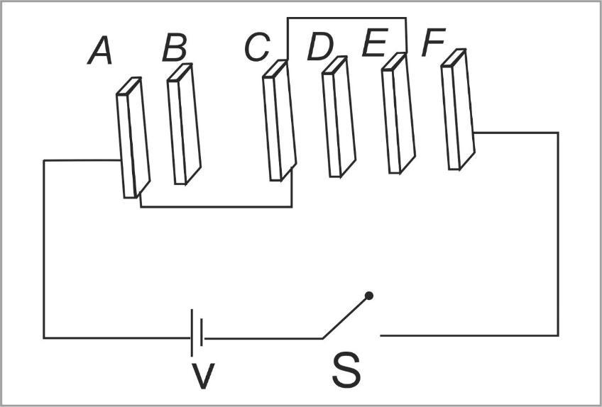
\[A\], \[B\], $C$, \[D\], \[E\] and \[F\] are conducting plates each of area \[A\] and any two consecutive plates are separated by a distance \[d\] as shown in the given figure. The energy in system after the switch \[S\] is closed is-
A) \[\dfrac{{3{\varepsilon _0}A}}{{2d}}{V^2}\]
B) \[\dfrac{{5{\varepsilon _0}A}}{{12d}}{V^2}\]
C) \[\dfrac{{{\varepsilon _0}A}}{{2d}}{V^2}\]
D) \[\dfrac{{{\varepsilon _0}A}}{d}{V^2}\]
Answer
249.6k+ views
Hint: Simplify the given figure in an easier circuit, where all the connections are clear, and the capacitors are placed accordingly. Then seeing the series and parallel conditions of the capacitors, the question can be solved. Also after simplifying the circuit one can see that most capacitors are short circuited(potential drop across them is zero hence charge on them will be zero)
Complete step by step answer:
In this question, we have given a combination of two plates, which forms a capacitor (a passive electronic component with two terminals) with a distance of ‘d’ units in between the plates. Now we know that the formula for capacitance of one capacitor is given as-
\[ \Rightarrow C = \dfrac{{{\varepsilon _0}A}}{d}\]
So, in order to find energy in the system we can apply the formula,
\[U = \dfrac{{{C_{eq}}{V^2}}}{2}......\left( 1 \right)\]
Where, \[{C_{eq}}\] is the equivalent capacitance of the entire circuit.
\[A\] is the plate area
\[V\] is the voltage across the circuit
Now simplifying the given figure, we get,
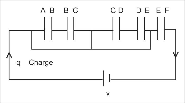
Now we can clearly say that the charge will flow through the conducting wires below the capacitors because it has no kind of hindrance and this will be till the charge \[q\] reaches the last capacitor only at that capacitor it will be stored. So, the middle capacitors are practically of no use. More technically we can say that The plates \[A\] and \[C\] are connected among themselves, hence the potential difference between the plates will be zero. Similar is the case for plates \[C\] and \[E\]. Hence the potential difference between plates \[C\] and \[E\] is also zero.
Therefore, no charge flows if there is no potential difference.
Therefore, the equivalent capacitance will be,
\[ \Rightarrow {C_{ed}} = \dfrac{{{\varepsilon _0}A}}{d}\]
Now we substitute the value of the equivalent capacitance in equation (1) as,
\[\therefore U = \dfrac{{{\varepsilon _0}A}}{{2d}}{V^2}\]
Thus, the correct option is (C).
Note: Always remember that charge flows from high potential area to low potential area and will always choose an easier and obstacle free path to travel in a circuit. And we are careful about the capacitor that is which one is in use or which is not in use in the circuit.
Complete step by step answer:
In this question, we have given a combination of two plates, which forms a capacitor (a passive electronic component with two terminals) with a distance of ‘d’ units in between the plates. Now we know that the formula for capacitance of one capacitor is given as-
\[ \Rightarrow C = \dfrac{{{\varepsilon _0}A}}{d}\]
So, in order to find energy in the system we can apply the formula,
\[U = \dfrac{{{C_{eq}}{V^2}}}{2}......\left( 1 \right)\]
Where, \[{C_{eq}}\] is the equivalent capacitance of the entire circuit.
\[A\] is the plate area
\[V\] is the voltage across the circuit
Now simplifying the given figure, we get,
Now we can clearly say that the charge will flow through the conducting wires below the capacitors because it has no kind of hindrance and this will be till the charge \[q\] reaches the last capacitor only at that capacitor it will be stored. So, the middle capacitors are practically of no use. More technically we can say that The plates \[A\] and \[C\] are connected among themselves, hence the potential difference between the plates will be zero. Similar is the case for plates \[C\] and \[E\]. Hence the potential difference between plates \[C\] and \[E\] is also zero.
Therefore, no charge flows if there is no potential difference.
Therefore, the equivalent capacitance will be,
\[ \Rightarrow {C_{ed}} = \dfrac{{{\varepsilon _0}A}}{d}\]
Now we substitute the value of the equivalent capacitance in equation (1) as,
\[\therefore U = \dfrac{{{\varepsilon _0}A}}{{2d}}{V^2}\]
Thus, the correct option is (C).
Note: Always remember that charge flows from high potential area to low potential area and will always choose an easier and obstacle free path to travel in a circuit. And we are careful about the capacitor that is which one is in use or which is not in use in the circuit.
Recently Updated Pages
JEE Isolation, Preparation and Properties of Non-metals Important Concepts and Tips for Exam Preparation
Isoelectronic Definition in Chemistry: Meaning, Examples & Trends
Ionisation Energy and Ionisation Potential Explained
Iodoform Reactions - Important Concepts and Tips for JEE
Introduction to Dimensions: Understanding the Basics
Instantaneous Velocity Explained: Formula, Examples & Graphs
Trending doubts
JEE Main 2026: Exam Dates, Session 2 Updates, City Slip, Admit Card & Latest News
Hybridisation in Chemistry – Concept, Types & Applications
JEE Main 2026 Application Login: Direct Link, Registration, Form Fill, and Steps
Understanding the Electric Field of a Uniformly Charged Ring
Derivation of Equation of Trajectory Explained for Students
JEE Main Marking Scheme 2026- Paper-Wise Marks Distribution and Negative Marking Details
Other Pages
CBSE Class 12 Physics Question Paper 2026: Download SET-wise PDF with Answer Key & Analysis
JEE Advanced Marks vs Ranks 2025: Understanding Category-wise Qualifying Marks and Previous Year Cut-offs
JEE Advanced 2026 - Exam Date (Released), Syllabus, Registration, Eligibility, Preparation, and More
JEE Advanced Weightage 2025 Chapter-Wise for Physics, Maths and Chemistry
Understanding the Angle of Deviation in a Prism
Understanding Centrifugal Force in Physics