


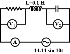
In the given circuit diagram power consumption is maximum then ratio of readings of voltmeters ${V_1}$ and ${V_2}$( Reading of ammeter is $2\;{\text{A}}$ ):
(A) $\dfrac{1}{5}$
(B) $5$
(C) $1$
(D) Data insufficient
Answer
232.8k+ views
Hint:- The impedance of the LCR circuit depends on the capacitive reactance and inductive reactance. For finding those values, we need the values of inductance and capacitance. Check whether those are given. And the power consumed depends on the current through the circuit.
Complete step by step solution:
In LCR circuits, the expression for the inductive reactance is given as,
${X_L} = \omega L$
Where, $\omega $ is the angular frequency and $L$ is the conductance.
And the expression for the capacitive reactance is given as,
${X_C} = \dfrac{1}{{\omega C}}$
Where, $C$ is the capacitance.
We have given the inductance as $L = 0.1\;{\text{H}}$ .
Therefore, ${X_L} - {X_C} = \omega L - \dfrac{1}{{\omega C}}$
Substitute the given value.
${X_L} - {X_C} = 0.1\omega - \dfrac{1}{{\omega C}}$
The value of capacitance is not given.
The expression for the impedance in the LCR circuit is given as,
$Z = \sqrt {{R^2} + {{\left( {{X_L} - {X_C}} \right)}^2}} $
Where, $R$ is the resistance of the circuit. The value of $R$ is not given.
From the figure, $V\sin \omega t = 14.14\sin 10t$
Thus the voltage across the circuit is $14.14$ .
For the power consumption, we have to find the current flowing through the circuit.
The expression for the current in the circuit is given as,
$I = \dfrac{V}{Z}$
Substituting in the above expression,
$I = \dfrac{{14.14}}{{\sqrt {{R^2} + {{\left( {{X_L} - {X_C}} \right)}^2}} }}$
The value of resistance and capacitance are not given. Hence the power consumed in this LCR circuit cannot be found.
Here the given data is insufficient to find the current in the circuit.
The answer is option D.
Note: If the question is given that the circuit is in resonance and the value of resistance is given the power consumption is easy to find. Hence the capacitive reactance and inductive reactance will be equal in resonance.
Recently Updated Pages
JEE Main 2026 Session 2 Registration Open, Exam Dates, Syllabus & Eligibility
JEE Main 2023 April 6 Shift 1 Question Paper with Answer Key
JEE Main 2023 April 6 Shift 2 Question Paper with Answer Key
JEE Main 2023 (January 31 Evening Shift) Question Paper with Solutions [PDF]
JEE Main 2023 January 30 Shift 2 Question Paper with Answer Key
JEE Main 2023 January 25 Shift 1 Question Paper with Answer Key
Trending doubts
JEE Main Marking Scheme 2026- Paper-Wise Marks Distribution and Negative Marking Details
Why does capacitor block DC and allow AC class 12 physics JEE_Main
Understanding Average and RMS Value in Electrical Circuits
Understanding Collisions: Types and Examples for Students
Ideal and Non-Ideal Solutions Explained for Class 12 Chemistry
Understanding Atomic Structure for Beginners
Other Pages
JEE Advanced Weightage 2025 Chapter-Wise for Physics, Maths and Chemistry
CBSE Class 12 Physics Set 2 (55/2/2) 2025 Question Paper & Solutions
Inductive Effect and Its Role in Acidic Strength
Degree of Dissociation: Meaning, Formula, Calculation & Uses
Units and Measurements Mock Test for JEE Main 2025-26 Preparation
Chemistry Question Papers for JEE Main, NEET & Boards (PDFs)