


How Does the Reciprocity Theorem Simplify Circuit Analysis?
The reciprocity theorem is one of the most significant network theorems in electricity and currents. The theorem was introduced by Max Theodor Felix von Laue. According to the reciprocity theorem, the value of current obtained in any branch of an electrical circuit or network due to a single voltage source (V) is equal to the value of current flowing through that branch when the source was first connected and when it was connected to the branch where the value of current was initially determined. The reciprocity theorem is described along with its statement and proof in the article.
History of Max Theodor Felix Von Laue
Max Theodor Felix von Laue, a German scientist who lived from 9 October 1879 to 24 April 1960, won the Nobel Prize in Physics in 1914 for his invention of the diffraction of X-rays by crystals. In 1935, von Laue demonstrated how to apply the reciprocity theorem to simplify the issue.

Max Theodor Felix Von Laue
Reciprocity Theorem Statement
Reciprocity Theorem states that the output reading of the ammeter in any electrical circuit would remain unchanged if the voltage source and ammeter were switched places.
In simple words, the reciprocity theorem implies that no matter how the current and voltage sources are arranged in a network, the magnitude of the current and voltage that flows through the circuit remains constant.
Steps for Using the Reciprocity Theorem to Solve a Network
Decide which branches need reciprocity to be developed first.
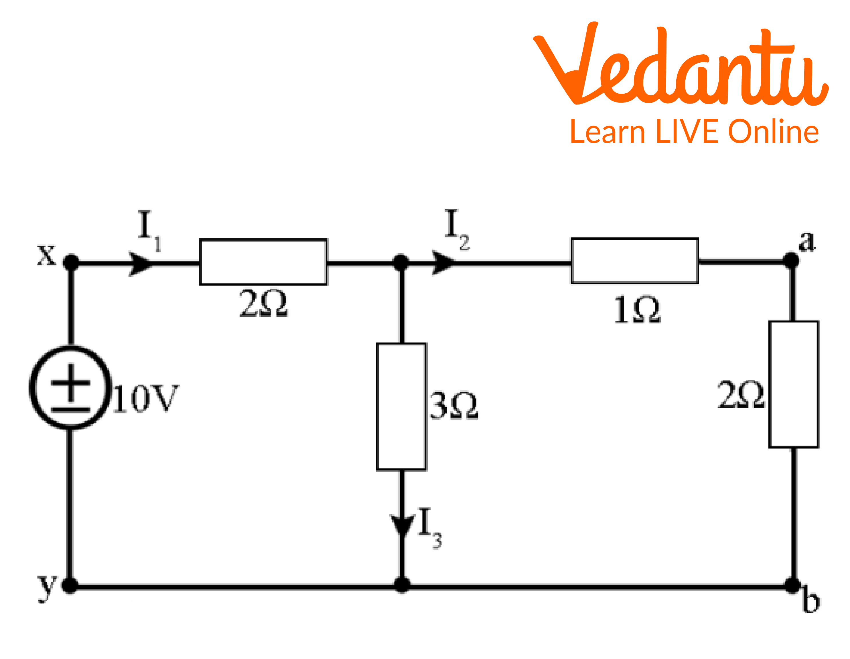
Consider that the sources are located in the branch x-y.
Reciprocity Theorem
The corresponding resistance across x-y, with reference to above figure, is given by
${R_{eq\;}}\; = \;\left[ {\left( {2 + 3} \right)||3} \right]\; + 2\;\\{R_{eq\;}}\; = \;3.5\Omega \\\therefore \;{I_1}\; = \dfrac{{\;10}}{{3.5}}\; = \;2.86A\\ \Rightarrow {I_2}\; = 2.86 \times \dfrac{3}{{3 + 3}}\; = \;1.43A\\ \Rightarrow {I_3}\; = \left( {2.86\; - 1.43} \right)\; = \;1.43A$
Any typical network analysis technique can be used to determine the current in the branch.
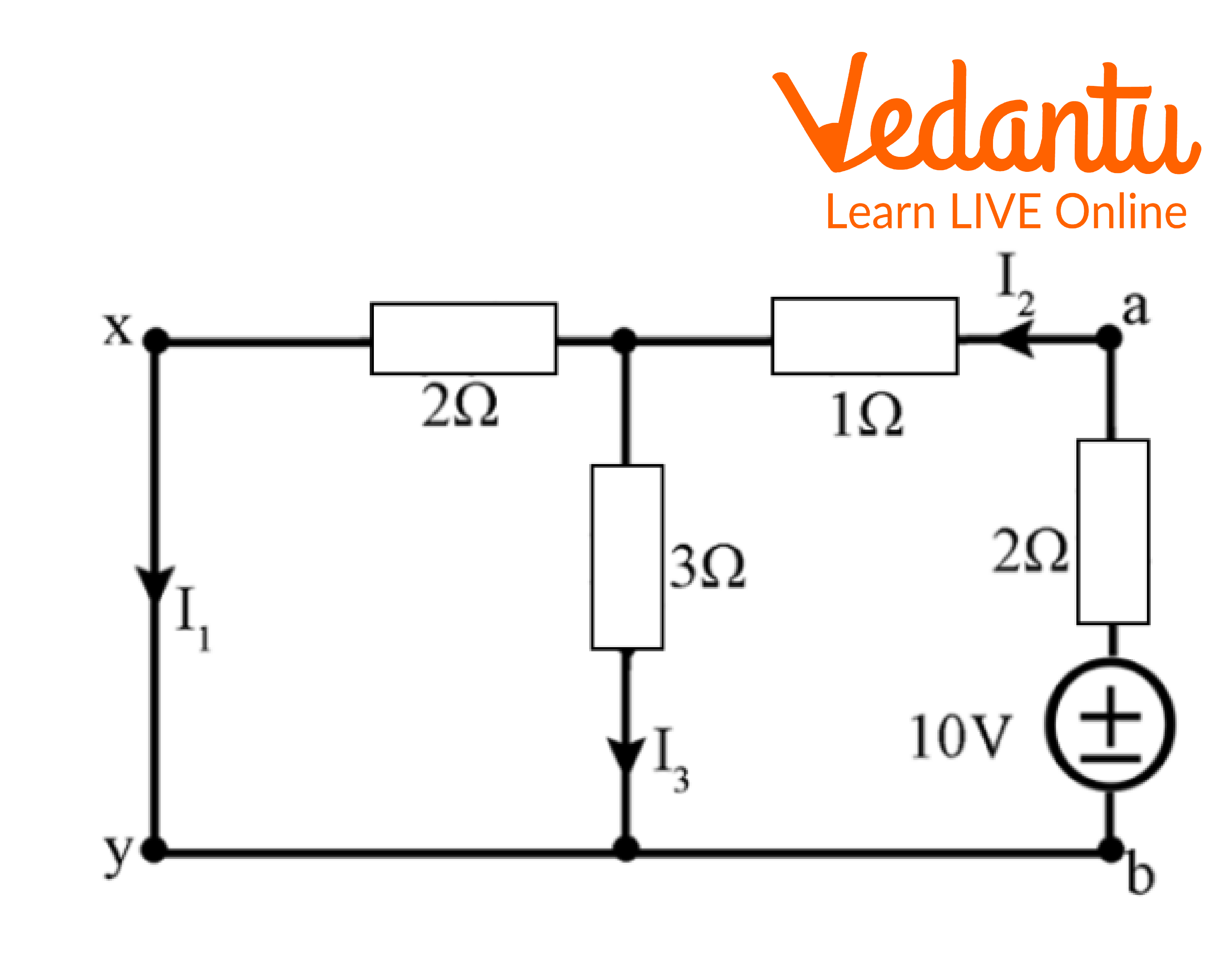
The branch that is chosen switches out the voltage source.
Reciprocity Theorem
\[{R_{eq\;}}\; = \;\left( {2||3} \right) + 1 + 2\;\;\\{R_{eq\;}}\; = \dfrac{6}{5} + 3\; = \;4.2\Omega \]
\[\therefore {I_{2\;}}\; = \dfrac{{\;10V}}{{4.2V}}\; = \;2.381\]
\[ \Rightarrow {I_1}\; = \;2.381 \times \dfrac{3}{{3 + 2}}\]
\[ \Rightarrow {I_1}\;\; = \;1.43A\]
The branch where the previous voltage source was located has its current calculated.
Now it can be observed that the current measured in the previous connection, or step 1, and the current computed when the source is switched, or in step 3, are the same.
Limitations of Reciprocity Theorem
Not applicable to circuits with any type of time-varying component.
Not relevant to circuits with dependent sources, even if they are linear.
Not applicable to circuits made up of nonlinear components like transistors, diodes, etc.
Application of Reciprocity Theorem
The reciprocity theorem can be applied to circuits with either a current source or a voltage.
This theorem is used to examine the ultrasonic produced when elastic bodies are heated to high temperatures on their surfaces.
This theorem is used to calculate surface waves caused by line loads on an irregular, transversely isotropic half-space.
Solved Examples
1. Does the reciprocity theorem apply to any of the following networks?
Containing both dependent and independent sources.
Having R, L, and C elements.
A system that is initially not relaxed.
Ans: Yes, the reciprocity theorem applies to the networks containing R, L, and C elements. So, the only viable option is option B because options A and C don't satisfy the requirements for applying this theorem.
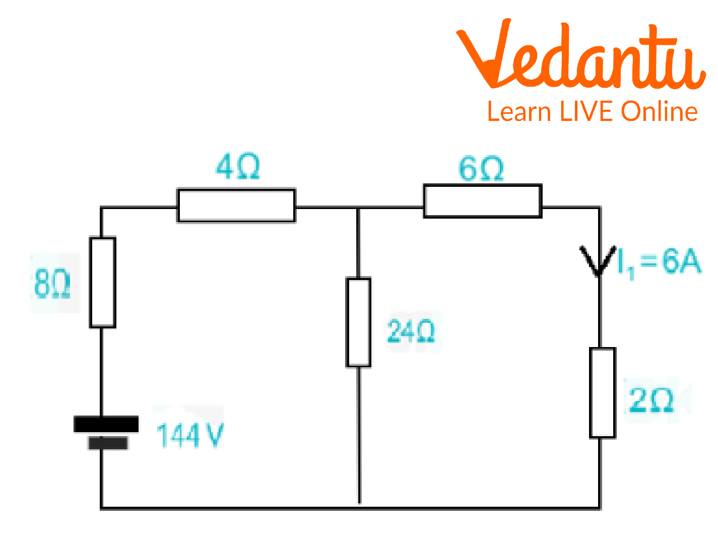
2. What will be the value of being \[{I_2}\] in the following figure if \[{I_1}\]in the given circuit is 6A?
Circuit Diagram
Circuit Diagram
Ans: Given data,
\[{I_1}\; = \;6V\]
\[{V_{1\;}}\; = \;144V\]
\[{V_2}\; = \;\;144V\]
\[{I_2}\; = \;?\]
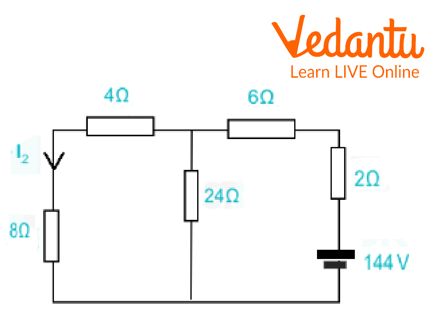
If a single voltage source v in the branch AB of any passive bilateral network results in a current response I in the branch CD, then the voltage source's removal from the branch AB and its insertion into the branch CD will result in the same current in the branch AB.
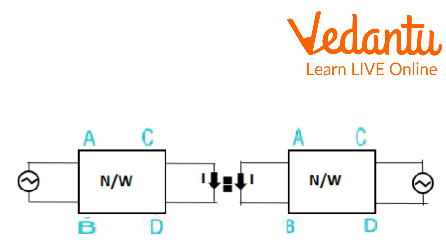
Circuit Diagram of Reciprocity Theorem
If the positions of excitation and responses are switched in the reciprocity theorem, the ratio stays the same.
\[\dfrac{{{V_1}}}{{{I_1}}} = \dfrac{{{V_2}}}{{{I_2}}}\]
Replace the terms with the known values,
\[\dfrac{{144}}{6}\; = \dfrac{{\;144}}{{{I_2}}}\]
\[144{I_2}\; = \;864\\{I_2}\; = \dfrac{{\;864}}{{144}}\]
\[{I_{2\;}}\; = \;6\;A\]
3. Demonstrate how the reciprocity theorem is applied to the network in the accompanying diagram.
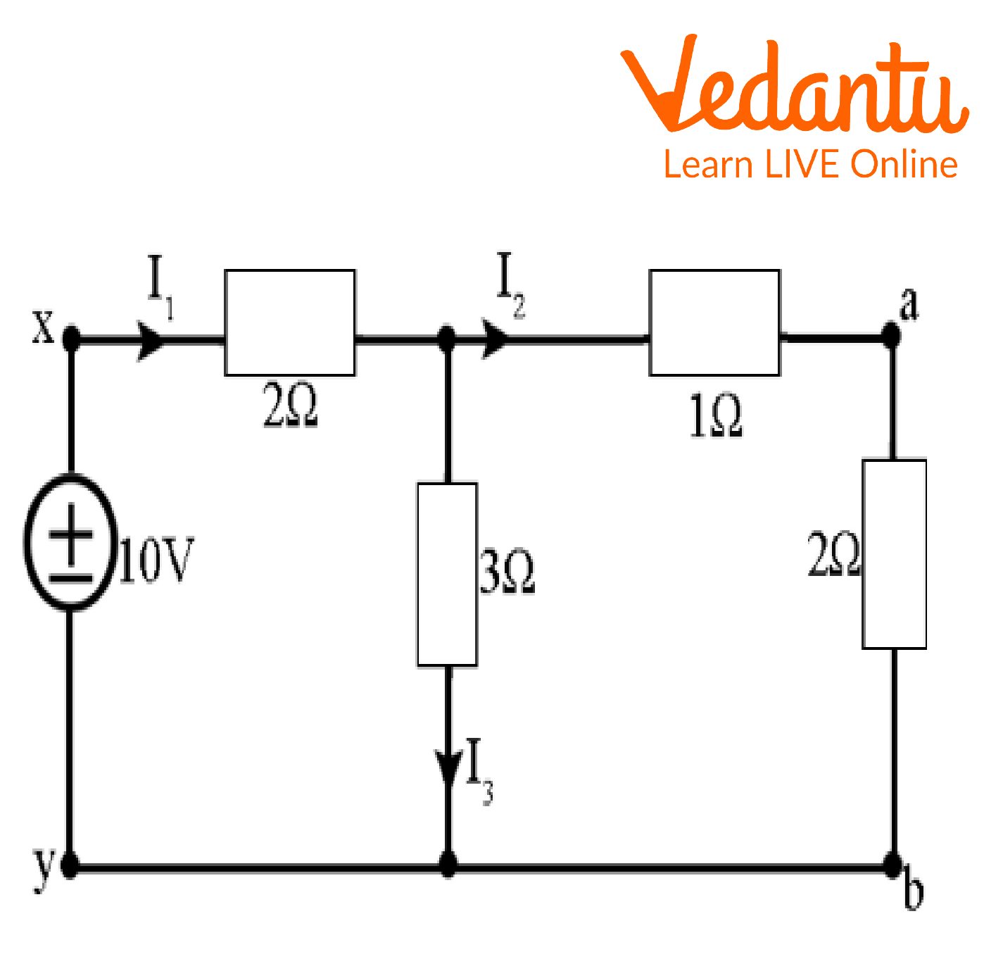
Circuit Diagram
Ans: The comparable resistance across x-y concerning the following figure is given by,
\[{R_{eq}}\; = \;\left[ {\left( {2 + 1} \right)||3} \right] + 2\;\]
\[{R_{eq}}\; = \;3.5\Omega \]
\[\therefore {I_1}\; = \dfrac{{\;10}}{{3.5}}\]
\[{I_1}\; = \; = \;2.86A\]
\[{I_2}\; = \;2.86 \times \dfrac{3}{{3 + 3}}\]
I2 = 1.43A
\[{I_3}\; = \;2.86 - \;1.43\]
\[{I_3}\; = \;1.43A\]
Now,
Circuit Diagram
\[{R_{eq}}\; = \;\left( {2||3} \right) + 1 + 3\]
\[{R_{eq}}\; = \dfrac{{\;6}}{5} + 3\]
\[{R_{eq}}\; = \dfrac{{\;21}}{5}\]
\[{R_{eq}}\; = 4.2\Omega \]
\[\therefore {I_2}\; = \dfrac{{\;10V}}{{4.2\Omega }}\]
\[{I_2}\; = \;2.381A\]
This implies
\[{I_1}\; = \;{I_2}\dfrac{3}{{3 + 2}}\]
\[{I_1}\; = \;2.381 \times \dfrac{3}{5}\]
\[{I_1}\; = \;1.43A\]
Important Points to Remember
Both AC and DC circuits are covered by the reciprocity theorem.
The circuit does not contain any time-varying components when applying the theorem.
It is feasible to determine if a network is linear or non-linear using the reciprocity theorem.
Conclusion
One of the most crucial electromagnetics theorems is the reciprocity theorem. This fundamental theorem explains that even if the locations of a network's voltage and current sources are switched, the circuit's current and voltage levels will remain constant. Many DC and AC networks that have numerous uses in electromagnetic electronics are solved using this theorem. There isn't a time-varying component in these circuits.
FAQs on Reciprocity Theorem Explained: Definition, Proof & Uses
1. What is the Reciprocity Theorem in simple terms?
In simple terms, the Reciprocity Theorem states that if you swap the locations of a voltage source and an ammeter in any linear, bilateral electrical network, the reading on the ammeter will remain exactly the same. It essentially describes a symmetrical relationship between the input (excitation) and the output (response) in a circuit.
2. What are the essential conditions for the Reciprocity Theorem to be valid?
For the Reciprocity Theorem to apply to a network, the network must meet specific criteria:
- Linearity: The relationship between voltage and current must be linear. The circuit should obey the principles of superposition.
- Bilaterality: The components (like resistors, inductors, capacitors) must allow current to flow equally well in either direction.
- Passive: The circuit should not contain any active elements like batteries or amplifiers within the network itself (the single source is external).
- No Dependent Sources: The theorem is not applicable to circuits that contain dependent voltage or current sources.
3. What is a common real-world example of the Reciprocity Theorem in action?
The most classic real-world application is in antenna theory. The theorem implies that an antenna's characteristics, such as its radiation pattern and impedance, are the same whether it is being used for transmitting a signal or receiving one. This simplifies antenna design and testing significantly, as engineers don't need to perform separate analyses for both modes.
4. Why doesn't the Reciprocity Theorem work for non-linear or unilateral circuits?
The theorem relies on the predictable, symmetrical behaviour of a circuit. In a non-linear circuit (like one with a diode), the response is not directly proportional to the input, so swapping them breaks this relationship. In a unilateral circuit, which has components like amplifiers, the signal is designed to flow in only one direction. Reversing the source and response positions would go against the circuit's fundamental design, making the theorem invalid.
5. How does the Reciprocity Theorem help in analysing complex electrical networks?
The primary benefit is simplification. It allows an engineer to analyse a complex circuit's behaviour from one point and be confident that the relationship between that point and another will be identical if their roles are reversed. This can save a great deal of calculation time. Instead of solving the entire network again after swapping the source and load, you can use the result from the initial analysis.
6. Is the Reciprocity Theorem the same as the Superposition Theorem?
No, they are different but related concepts for linear circuits. The Superposition Theorem helps find the total response in a circuit with multiple sources by calculating the effect of each source individually and then adding them up. The Reciprocity Theorem, on the other hand, deals with the symmetrical behaviour of a single source and its response within a network.
7. Can the Reciprocity Theorem be applied to circuits that have both a current source and a voltage source?
The basic Reciprocity Theorem is stated for a network with a single independent source. If a circuit has multiple independent sources (like a voltage source and a current source), you must first use the Superposition Theorem to turn it into a single-source problem. You would find the response from each source one at a time (while deactivating the others) before you could apply the concept of reciprocity.