


Revision Notes on Electromagnetic Induction for NEET 2026 - Free PDF Download
Experiments of Faraday and Henry:
The discovery and understanding of electromagnetic induction was the result of extensive research by Faraday and Henry. We'll discuss a few of these trials presently.
Experiment 1:
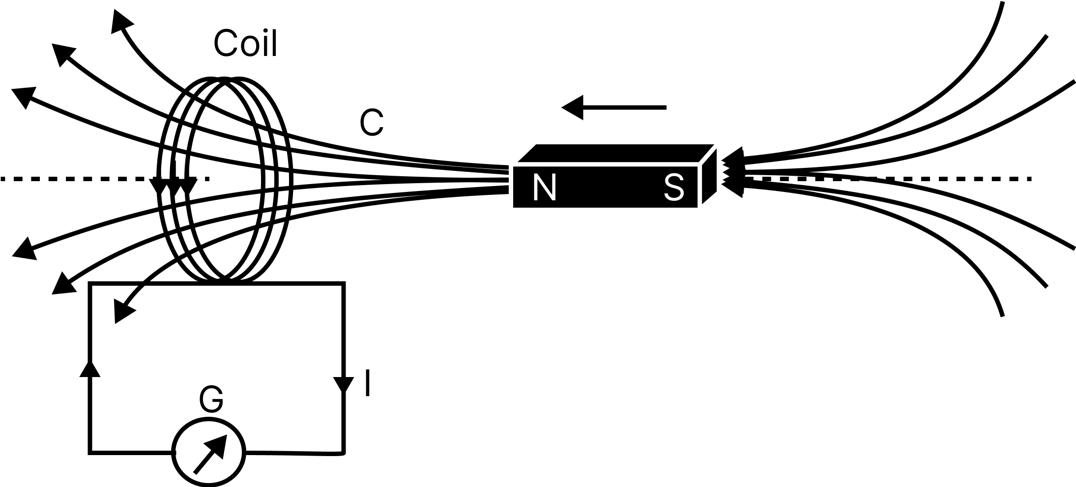
In the picture below, a coil C is linked to a galvanometer G. The galvanometer's pointer deflects when the North pole of a bar magnet is pushed towards the coil, showing the existence of electric current in the coil. As long as the bar magnet is moving, the deflection remains permanent. There is no deflection in the galvanometer when the magnet is not moved and is maintained stationary. When the magnet is pulled away from the coil, the galvanometer deflects in the opposite direction, indicating that the current has changed.
Experiment 1
When the South-pole of the bar magnet is pushed closer or away from the coil, the deflections in the galvanometer are the polar opposite of those detected for comparable movements with the North-pole.Furthermore, the deflection (and consequently current) is shown to be bigger when the magnet is pushed towards or withdrawn away from the coil at a quicker rate. Instead, the same effects are observed when the bar magnet is maintained fixed and coil C is moved closer or away from the magnet. It illustrates that the relative motion of the magnet and the coil generates (induces) electric current in the coil.
Experiment 2:
In the diagram below, the bar magnet is replaced with a second coil C2 that is powered by a battery. A continuous magnetic field is produced by the constant current in coil C2 . As coil C2 is brought closer to coil C1, the galvanometer deflects. This means that an electric current is being generated in coil C1. When C2 moves away in the other direction, the galvanometer deflects again.The deflection will continue as long as coil C2 moves. When coil C2 is fixed and coil C1 is shifted, the same results are observed. The relative motion of the coils, once again, causes the electric current to flow.

Experiment 2
Experiment 3:
The preceding two experiments utilised a magnet and a coil, as well as two coils moving relative to each other. In another experiment, Faraday established that relative motion is not an absolute need. The illustration shows two coils, C1 and C2, that are maintained motionless. Coil C1 is linked to the galvanometer G, whereas coil C2 is connected to the battery and a tapping key K.

Experiment 3
If the tapping key K is pushed, the galvanometer briefly deflects. The pointer on the galvanometer quickly returns to zero. If the key is held down continuously, there is no deflection in the galvanometer. When the key is released, there is a momentary deviation in the opposite direction. The deflection rises considerably when an iron rod is placed into the coils along their axis.
Electromagnetic Induction
"When the magnetic flux in a closed circuit changes, an induced emf is generated in the circuit, and current is induced in the circuit as a result.
This emf only lasts as long as the flux change does." Electromagnetic induction is the term for this phenomenon.
Magnetic Flux:
Magnetic Flux
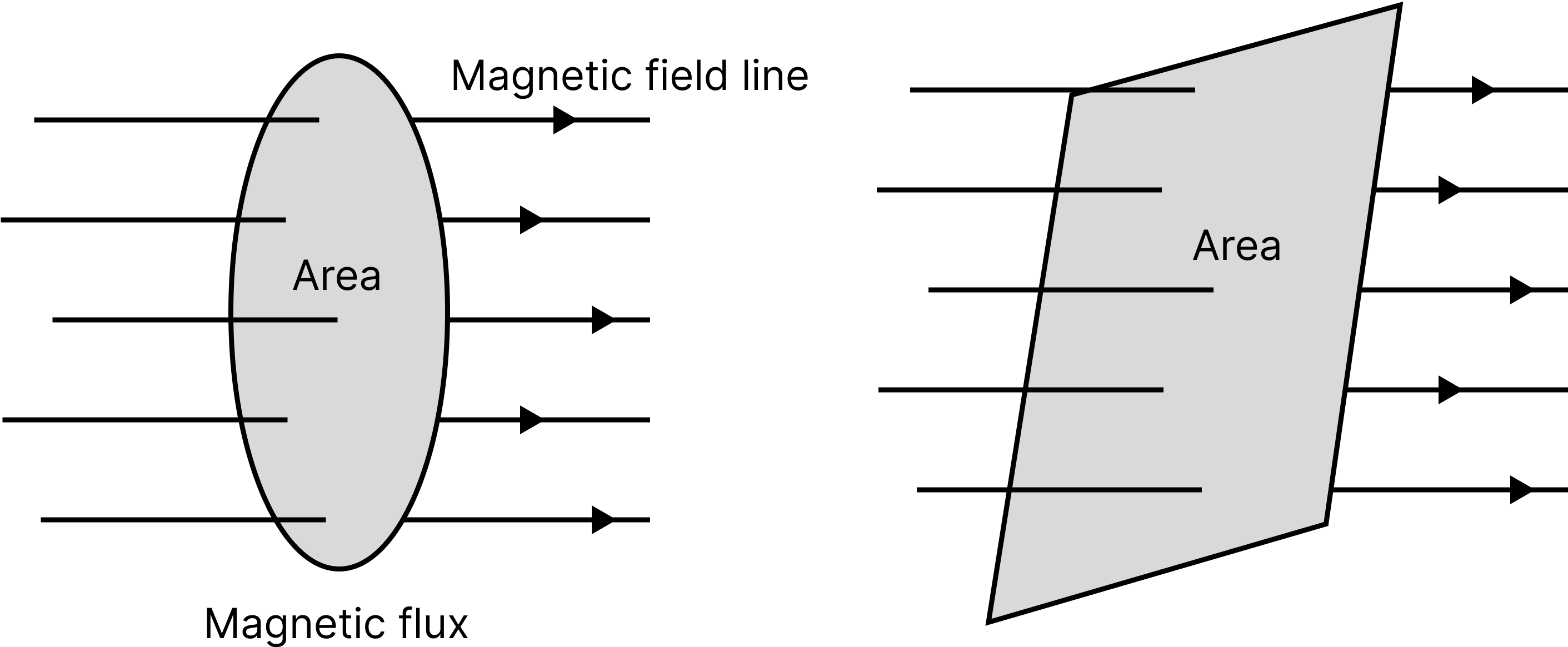
The product of the area and the component of B that is perpendicular to that area is the magnetic flux aligned with the surface.
$\phi_{B}=\vec{B} \cdot \vec{A}=B A \cos \theta$ and
$\phi_{\mathrm{B}}=\mu n \mathrm{AH}$
where, $\mu$ is the permeability of the medium, $n$ is the number of turns, $A$ is the area and $H$ is the magnetic field intensity.
(a) When $\theta=90^{\circ}, \cos \theta=0$. So, $\phi_{\mathrm{B}}=0$
This means that when the field is parallel to the surface, there is no magnetic flux associated with the surface.
(b) When $\theta=0^{\circ}, \cos \theta=1 .$ So, $\left(\phi_{B}\right)_{\max }=1$
This means that the magnetic flux associated with a surface is greatest when the area is kept perpendicular to the field's direction.
Faraday's Laws of Electromagnetic Induction
The First Law An induced emf is created in the circuit whenever the magnetic flux associated with a coil changes.
Second Law The negative rate of change of magnetic flux equals the induced emf.
$e=-\dfrac{\Delta \phi }{\Delta t}\text{. }$
If circuit has a coil of $N$ turns, then $e=-\dfrac{\Delta (N\phi )}{\Delta t}$
Induced electric field:-
e.m.f $=\int \vec{E} d \vec{l}$
Induced Current and Induced Charge
If a circuit have a resistance$(R)$, then
Induced current, $i=\dfrac{N}{R}\dfrac{\Delta \phi }{\Delta t}$.
Induced charge, $q=\dfrac{N}{R}\Delta \phi $. Where, $R=$ resistance of the circuit.
Properties of Magnet:
Attractive Property: A magnet may attract small bits of magnetic materials such as iron, steel, cobalt, nickel, and other similar metals. At poles, the attraction is greatest. Poles that are unlike one other attract each other, while poles that are similar repel each other.
The Directive Property: When suspended freely, a magnet aligns itself roughly along the geographical N-S line.
Magnetic Poles Exist in Pairs: The S-poles of a magnet are not split when it is divided into two equal pieces transverse to their length.
Lenz's Law
"The induced emf's orientation is such that it opposes the change that creates it."
Lenz Law
The Lenz law is a type of energy conservation law. If the North pole of a bar magnet approaches a coil, the direction of induced current in the coil will be anti-clockwise, forming the North Pole, and thus opposing the approaching of the North Pole.
Similarly, if the North Pole moves away from a coil, the induced current will flow clockwise to produce the South Pole, which will counter the North Pole's movement.
Formula:$\varepsilon=-N \dfrac{d \Phi B}{d t}$
Induced emf in a Conducting Rod in Different Situations
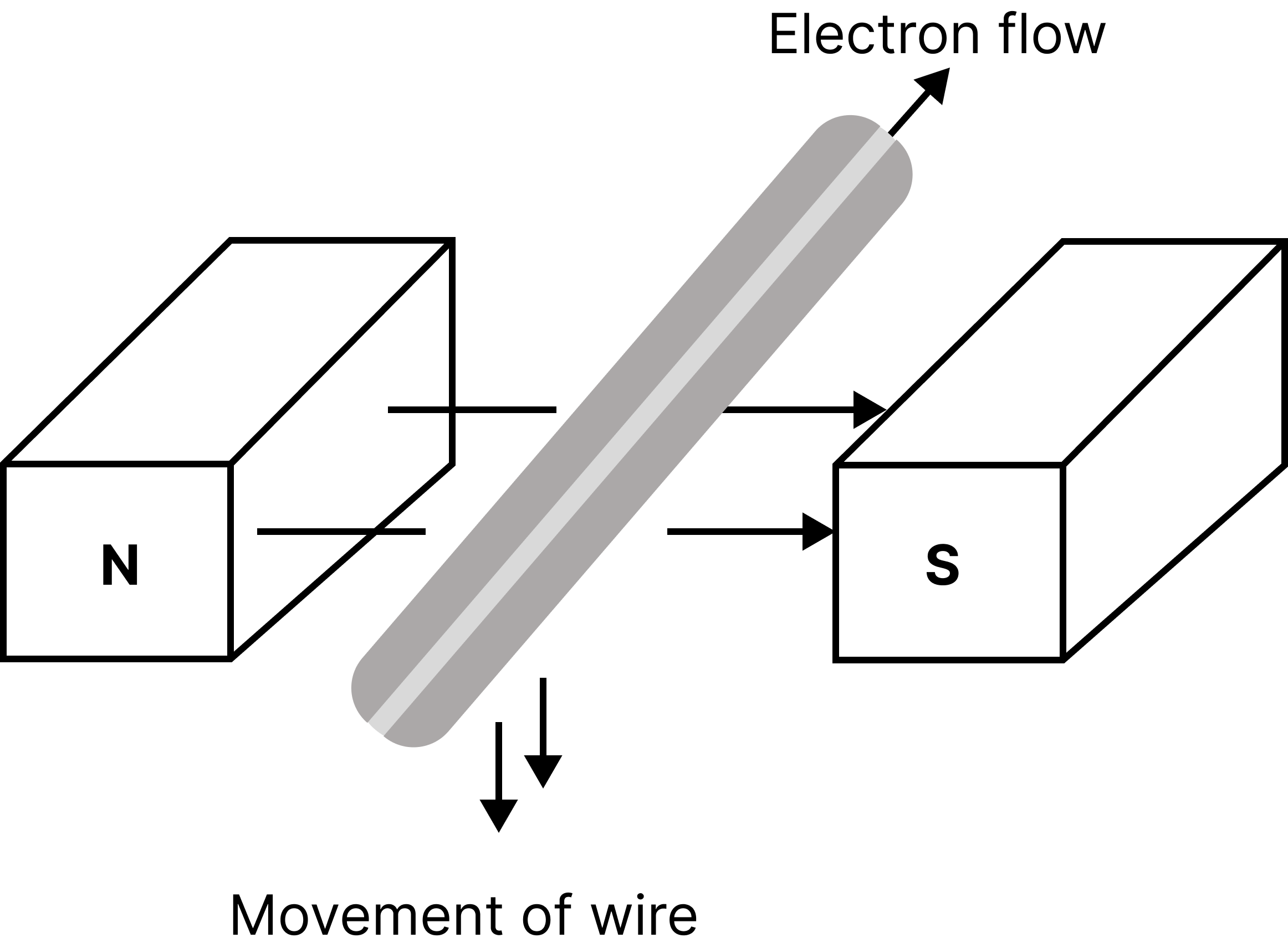
If a conductor of length $l$ is moving perpendicularly in a magnetic field, then induced potential difference across the ends of conductor $e=Bvl$.
If the direction of velocity makes an angle $\theta$ with the direction of the magnetic field, then $e=Bvl\sin \theta$.
emf induced in rod of length $l$ rotating about an end in a uniform magnetic field is
$e=\dfrac{B\omega {{l}^{2}}}{2}$
Here, $\omega $ is the angular speed
Types of Electromagnetic Induction
There are two forms of electromagnetic induction.
Self-induction: Self-induction occurs when the current flowing through a coil changes, causing induced current to flow through the same coil.
Coefficient of self-inductance of a coil is $L=-e \dfrac{d t}{d I}$
Coefficient of self-inductance of a solenoid $L=\dfrac{{{\mu }_{0}}{{N}^{2}}A}{l}$
Here, $L$ is the length of the solenoid, $A$ is area, $N$ is the number of turns and $i$ is current flowing through the coil.
The 'Henry' or volt/amp/second unit of self-inductance coefficient.
Coefficient of Self-inductance of Two Coils in Series
The effective self inductance is $L_{s}=L_{1}+L_{2}$.
If the mutual inductance coefficient between the two coils is $\mathrm{M}$ and they have flux linkage in the same sense, then $L=L_{1}+L_{2}+2 M$.
And for flux linkage in opposite direction
$L=L_{1}+L_{2}-2 M$
Coefficient of Self-inductance of Two Coils in Parallel
$\dfrac{1}{L_{p}}=\dfrac{1}{L_{1}}+\dfrac{1}{L_{2}}$
Mutual Induction: When two coils are placed near together, a change in current in one coil causes emf to be produced in the other coil.
The mutual inductance coefficient is equal to $M=\dfrac{{{N}_{2}}{{\phi }_{2}}}{{{i}_{1}}}\quad $ or $\quad M=\dfrac{-{{e}_{2}}}{\Delta {{i}_{1}}/\Delta t}$
Here, ${{R}_{1}}$ and ${{R}_{2}}$ are radius of the coils
In case of a solenoid having primary coil ${{N}_{1}}$ and secondary coil ${{N}_{2}}$ turns, then $M=\dfrac{{{\mu }_{\text{c}}}{{\mu }_{r}}{{N}_{1}}{{N}_{2}}A}{l}$
Here, $l$ is the length of solenoid and $A$ is area.
Coefficient of Coupling of the Two Circuits

Coefficient of Coupling of the Two Circuits
Let's calculate mutual inductance between two circuits in terms of each circuit's self-inductance. Consider the case of maximal flux coupling, in which the total flux associated with one coil links with that of the other. Consider the following scenario: two coils are positioned next to each other
${{M}_{12}}=\dfrac{{{N}_{2}}{{\phi }_{{{B}_{2}}}}}{{{i}_{1}}}\quad \text{ and }\quad {{M}_{21}}=\dfrac{{{N}_{1}}{{\phi }_{{{B}_{1}}}}}{{{i}_{2}}}$
Similarly, $\quad {{L}_{1}}=\dfrac{{{N}_{1}}{{\phi }_{{{B}_{1}}}}}{{{i}_{1}}}$ and $\quad {{L}_{2}}=\dfrac{{{N}_{2}}{{\phi }_{{{B}_{2}}}}}{{{i}_{2}}}$
If all of coil 2's flux connects to coil 1 and vice versa, then ${{\phi }_{{{B}_{2}}}}\text{ }={{\phi }_{{{B}_{1}}}}$
$\text{ Since, }\quad {{M}_{12}}\text{ }={{M}_{21}}=M,\text{ hence, we have }$
${{M}_{12}}{{M}_{21}}\text{ }={{M}^{2}}=\dfrac{{{N}_{1}}{{N}_{2}}{{\phi }_{{{B}_{1}}}}{{\phi }_{{{B}_{2}}}}}{{{{\dot{t}}}_{1}}{{i}_{2}}}={{L}_{1}}{{L}_{2}}$
$\therefore \quad {{M}_{\max }}\text{ }=\sqrt{{{L}_{1}}{{L}_{2}}}$
This is the maximum possible value of $M$ as the total flux associated with one coil links with the other. In general only a fraction ${{K}_{2}}(<1)$ of ${{\phi }_{{{B}_{2}}}}$ passes through the coil 1. Similarly a fraction ${{K}_{1}}(<1)$ of ${{\phi }_{B}}$ passes through coil 2 .
Hence, $\quad {{\phi }_{{{B}_{1}}}}={{K}_{2}}{{\phi }_{{{B}_{2}}}}$ And $\quad {{\phi }_{{{B}_{2}}}}={{K}_{1}}{{\phi }_{{{B}_{1}}}}$
${{M}_{21}}{{M}_{12}}={{M}^{2}}=\dfrac{{{N}_{1}}{{N}_{2}}{{K}_{1}}{{K}_{2}}{{\phi }_{{{B}_{1}}}}{{\phi }_{{{B}_{2}}}}}{{{i}_{1}}{{i}_{2}}}={{K}_{1}}{{K}_{2}}{{L}_{1}}{{L}_{2}}$
$M=K\sqrt{{{L}_{1}}{{L}_{2}}}$ $(K\le 1)$
Here, $K=\sqrt{{{K}_{1}}{{K}_{2}}}$ is a number, depending on the geometry of the coils and their relative closeness having value between 0 and 1 .
Magnetic Resonance Image
The presence of hydrogen atoms in tissues causes it to be produced. Magnetic resonance is produced by the nucleus of hydrogen atoms. Nuclear magnetic resonance is the term for it.
A particular coil absorbs the resonance and sends it to the computer. This method is used to examine the many functions of the brain.
Motion of a loop in a magnetic field when whole of the coil is in the magnetic field:
(a) Motional e.m.f, $E=0$
(b) Resultant Current, $I=0$
(c) Force, $F=0$
(d) Power, $P=0$
Transformer
It's a static electrical device that's used on AC circuits to step up a low voltage to a high voltage or step down a high voltage to a low value.
The electromagnetic induction principle governs the operation of a transformer.
Step-up Transformer
The primary voltage of a step-up transformer is raised to a greater level.
Step-up transformers are those in which the number of turns on the secondary coil exceeds the number of turns on the primary coil.
Step-down Transformer
The primary voltage is stepped down using a step-down transformer. A step down transformer is defined as one in which the secondary coil has fewer turns than the primary coil.
For transformer $\dfrac{{{I}_{S}}}{{{I}_{P}}}=\dfrac{{{V}_{P}}}{{{V}_{s}}}=\dfrac{{{N}_{P}}}{{{N}_{S}}}=k$
Here, ${{I}_{p}}$ and ${{I}_{S}}=$ current in primary and secondary coil.
${{V}_{P}}$ And ${{V}_{S}}=$ potential in primary and secondary coil.
${{N}_{p}}$ And ${{N}_{S}}=$ Number of turns in primary and secondary.
Eddy Current:
According to Faraday's law of induction, eddy currents are loops of electrical current induced within conductors by a changing magnetic field in the conductor. Eddy currents flow in planes perpendicular to the magnetic field in closed loops within conductors.
Many experiments have been conducted to explain eddy currents, similar to Lenz's law. The initial test revealed that a soft iron core is inserted within a solenoid and is coupled to an alternating electromotive force. When the metallic disc is put over the soft iron core, the circuit is activated, and the metallic disc is flung up away from the iron core.
Important Formula Chart:
Example 1: A small square loop of side 'a' and one turn is placed inside a larger square loop of side $b$ and one turn ( $b>>a$ ). The two loops are coplanar with their centres coinciding. If a current $I$ is passed in the square loop of side 'b', then the coefficient of mutual inductance between the two loops is :
(A) $\dfrac{\mu_{0}}{4 \pi} 8 \sqrt{2} \dfrac{a^{2}}{b}$
(B) $\dfrac{\mu_{0}}{4 \pi} \dfrac{8 \sqrt{2}}{a}$
(C) $\dfrac{\mu_{0}}{4 \pi} 8 \sqrt{2} \dfrac{b^{2}}{a}$
(D) $\dfrac{\mu_{0}}{4 \pi} \dfrac{8 \sqrt{2}}{b}$
Answer: A
$B=\left[\dfrac{\mu_{0}}{4 \pi} \dfrac{I}{b / 2} \times 2 \sin 45\right] \times 4$
$\phi=2 \sqrt{2} \dfrac{\mu_{0}}{\pi} \dfrac{I}{b} \times a^{2}$
$\therefore M=\dfrac{\phi}{I}=\dfrac{2 \sqrt{2} \mu_{0} a^{2}}{\pi b}=\dfrac{\mu_{0}}{4 \pi} 8 \sqrt{2} \dfrac{a^{2}}{b}$
Option (a) is the correct answer.
Example 2:Two coaxial solenoids are made by winding thin insulated wire over a pipe of cross-sectional area $A=10$ $\mathrm{cm}^{2}$ and length $=20 \mathrm{~cm}$. If one of the solenoids has 300 turns and the other 400 turns, their mutual inductance is $\left(\mu_{0}=4 \times 10^{-7} \mathrm{~T} \mathrm{~mA}^{-1}\right)$
(a) $2.4 \pi \times 10^{-4} \mathrm{H}$
(b) $2.4 \pi \times 10^{-5} \mathrm{H}$
(c) $4.8 \pi \times 10^{-4} \mathrm{H}$
(d) $4.8 \pi \times 10^{-5} \mathrm{H}$
Answer: a
Explanation:
$M=\mu_{0} n_{1} n_{2} \pi r_{1}{ }^{2}$
From $\Phi_{2}=\pi r_{1}{ }^{2}\left(\mu_{0} n_{i}\right) n_{2} 1$
$A=\pi r_{1}{ }^{2}=10 \mathrm{~cm}^{2}, 1=20 \mathrm{~cm}, N_{1}=300, N_{2}=400 $
$M=\mu_{0} N_{1} N_{2} / l$
$M=\left(4 \pi \times 10^{-7} \times 300 \times 400 \times 10 \times 10^{-4}\right) / 0.20=2.4 \pi \times 10^{-4} \mathrm{H}$
Hence, the value of mutual inductance is $2.4 \pi \times 10^{-4} \mathrm{H}$.
Common Errors or Mistakes That Should Be Avoided by the Students Keeping the Exam Point of View:
Students forget to write the working formula.
Students also write improper units without checking their compatibility.
Calculation errors when doing problems
Students forget to put in the correct data they used in the working formula, which is used by teachers to check how effective the students' learning is.
A law stated by someone cannot be restructured, it should be reiterated like how it was stated.
For questions which require the reason for a certain condition, firstly students are required to state the cause of the condition and then the consequence of the condition.
Importance of Class 12 Physics Electromagnetic Induction
Electromagnetic induction is the core of many appliances and electrical components used in the modern world. This chapter is a crucial part of the NEET Physics syllabus, teaching students how this phenomenon can be theorised and used to make such devices.
This chapter is all about the effect of a changing magnetic field producing an electric current in a nearby conductor. Due to the fluctuating magnetic field, an electromotive force is created in an adjacent conductor. The intensity of the electromotive force can be calculated using the laws explained in this chapter.
It also explains how a conductor can be moved in a static magnetic field. The same effect of a fluctuating magnetic field can be seen in the moving conductor. It results in the formation of an electromotive force and an electric current starts to flow in the conductor.
Students will learn what magnetic flux is and how it can be measured. Faraday’s law of electromagnetic induction will be explained using scientific principles and mathematical expressions. Similarly, students will learn how different types of motions and shapes of conductors can influence the production of an electric current. Students can refer to the Electromagnetic Induction NEET notes and understand these effects of magnetism and the induction of current. They will become capable of calculating magnetic flux, power, and self-induction in different cases.
Benefits of Vedantu’s Electromagnetic Induction NEET Notes
These revision notes have been curated by the top subject matter experts keeping the common doubts and difficulties faced by the students while studying electromagnetic induction. Hence, these notes will be the perfect companion you can find to study this chapter efficiently.
All the concepts, laws, scientific principles, and derivations will be explained in a precise manner in these concise notes. You will be able to reduce your time for preparing and revising this chapter considerably. Make your study time more productive by performing Electromagnetic Induction Class 12 notes PDF download.
Use the simpler description of the concepts to solve sample questions given in these notes. Learn from the techniques of answering NEET questions framed by the experts. Evaluate your preparation level by focusing on these techniques.
Download Electromagnetic Induction NEET Notes PDF
Enjoy the convenience of referring to these notes according to your study schedule. The format used by the experts to compile these notes will help you recall the formulae, laws, and derivations faster. Use these revision notes to remember the scientific laws and principles of electromagnetic induction taught in this chapter without any difficulty.
Important Related Links for NEET

FAQs on Revision Notes on Electromagnetic Induction for NEET 2026
1. What is the induction of current?
According to the Electromagnetic Induction NEET notes PDF, the induction of current implies the production of electric current in a conductor due to the effect of any factor. It can be due to a fluctuating magnetic field near the conductor or a generator connected to the conductor.
2. Write one use of electromagnetic induction?
A common use of electromagnetic induction can be found in electric generators. Generators convert the kinetic energy of the coils to generate electricity and provide power to a house or industrial space.
3. What is a parallel combination?
When the beginning and end of conductors in an electrical circuit are common, it is called a parallel combination.
4. What is magnetism?
The physical phenomenon where an uncharged body attracts or repels another body is called magnetism.