


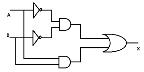
Which of the following logic expressions represents the logic diagram shown?
A) $X = A\overline B + \overline A B$
B) \[X = AB + \overline {AB} \]
C) \[X = \overline {AB} + \overline {AB} \]
D) \[X = \overline {AB} + AB\]
Answer
265.2k+ views
Hint: Just remember how AND, NOT, OR gates are working and what will be the resultant signal. Different gates will give different signals when an electrical signal is passed through the gates or the combination of the gates.
Complete step by step solution:
We know A Logic Gate is assigned as an elementary building block of digital circuits. The reason for which the computers are capable of performing complex operations is due to the interconnection of these logic gates. Logic gate is considered as a device which has the ability to produce one output level with the combinations of input levels. There are mainly 7 types of logic gates that are used in expressions. By combining them in different ways, you will be able to implement all types of digital components.
The 7 logic gates are:
i) NOT Gate
ii) AND Gate
iii) OR Gate
iv) NAND Gate
v) NOR Gate
vi) EXCLUSIVE OR Gate
vii) EXCLUSIVE NOR Gate
Let’s take a look at a given logic gates in the question
NOT Gate:
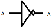
In NOT Gate, If two signal $A$ is given to the gate, the resultant will be $\overline A $
AND Gate:
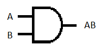
In AND Gate, If two signal $A$ and $B$ are given to the gate, the resultant will be $AB$
OR Gate:
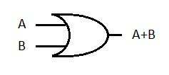
In OR Gate, If two signal $A$ and $B$ are given to the gate, the resultant will be $A + B$
We are dividing the question into two circuit to understand the inputs and outputs,
Circuit P: Signal $A$ and $B$ passes through different NOT gates and their resultant will be \[\overline A \] and \[\overline B \]
And these resultant signal goes to the AND gate as inputs and its resultant will be $\overline {AB} $
Circuit Q: Signals $A$ and $B$ are passing through AND gate as two inputs, and their resultant will be $AB$.
Now the resultant of Circuit P and circuit Q ie, $\overline {AB} $ and $AB$ are passing through the OR gate as input signals and the resultant will be \[\overline {AB} + AB\]
This is the final output.
So the final answer is option (D), \[X = \overline {AB} + AB\].
Note: Logic gates are implemented by using transistors, diodes, relays, optics and molecules or even by several mechanical elements. Due to this reason logic gates can also be considered as electronic circuits. A table which lists out the combination of input variables and the corresponding output variables is termed as a truth table.
Complete step by step solution:
We know A Logic Gate is assigned as an elementary building block of digital circuits. The reason for which the computers are capable of performing complex operations is due to the interconnection of these logic gates. Logic gate is considered as a device which has the ability to produce one output level with the combinations of input levels. There are mainly 7 types of logic gates that are used in expressions. By combining them in different ways, you will be able to implement all types of digital components.
The 7 logic gates are:
i) NOT Gate
ii) AND Gate
iii) OR Gate
iv) NAND Gate
v) NOR Gate
vi) EXCLUSIVE OR Gate
vii) EXCLUSIVE NOR Gate
Let’s take a look at a given logic gates in the question
NOT Gate:
In NOT Gate, If two signal $A$ is given to the gate, the resultant will be $\overline A $
AND Gate:
In AND Gate, If two signal $A$ and $B$ are given to the gate, the resultant will be $AB$
OR Gate:
In OR Gate, If two signal $A$ and $B$ are given to the gate, the resultant will be $A + B$
We are dividing the question into two circuit to understand the inputs and outputs,
Circuit P: Signal $A$ and $B$ passes through different NOT gates and their resultant will be \[\overline A \] and \[\overline B \]
And these resultant signal goes to the AND gate as inputs and its resultant will be $\overline {AB} $
Circuit Q: Signals $A$ and $B$ are passing through AND gate as two inputs, and their resultant will be $AB$.
Now the resultant of Circuit P and circuit Q ie, $\overline {AB} $ and $AB$ are passing through the OR gate as input signals and the resultant will be \[\overline {AB} + AB\]
This is the final output.
So the final answer is option (D), \[X = \overline {AB} + AB\].
Note: Logic gates are implemented by using transistors, diodes, relays, optics and molecules or even by several mechanical elements. Due to this reason logic gates can also be considered as electronic circuits. A table which lists out the combination of input variables and the corresponding output variables is termed as a truth table.
Recently Updated Pages
JEE Main 2025-26 Experimental Skills Mock Test – Free Practice
JEE Main 2025-26 Electronic Devices Mock Test: Free Practice Online
JEE Main 2025-26 Mock Tests: Free Practice Papers & Solutions
JEE Main 2025-26: Magnetic Effects of Current & Magnetism Mock Test
JEE Main 2025-26 Atoms and Nuclei Mock Test – Free Practice Online
JEE Main Mock Test 2025-26: Experimental Skills Chapter Online Practice
Trending doubts
JEE Main 2026: Exam Dates, Session 2 Updates, City Slip, Admit Card & Latest News
JEE Main Participating Colleges 2026 - A Complete List of Top Colleges
Kinematics Mock Test for JEE Main 2025-26: Practice & Ace the Exam
Kinematics Mock Test for JEE Main 2025-26: Comprehensive Practice
Hybridisation in Chemistry – Concept, Types & Applications
Understanding the Electric Field of a Uniformly Charged Ring
Other Pages
CBSE Class 12 Physics Question Paper 2026: Download SET-wise PDF with Answer Key & Analysis
JEE Advanced 2026 Notification Out with Exam Date, Registration (Extended), Syllabus and More
JEE Advanced Percentile vs Marks 2026: JEE Main Cutoff, AIR & IIT Admission Guide
JEE Advanced 2026 Marks vs Rank: Estimate IIT Rank from Your Score
JEE Advanced Weightage Chapter Wise 2026 for Physics, Chemistry, and Mathematics
Derivation of Equation of Trajectory Explained for Students