


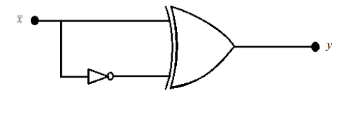
The output Y of the logic circuit given below is:-
A. \[1\]
B. \[0\]
C. \[X\]
D. \[\overline X \]
Answer
250.8k+ views
Hint: Here in this question, we need to determine the output of the logic circuit. The given circuit is a combination of the two gates, first is a NOT gate, and the second is the XOR gate, the output from the NOT gate will be one of the inputs for the XOR gate in the circuit, using the TRUTH TABLE we will find the result.
Complete step by step solution:
In the given circuit we can see the first logical gate is the NOT gate and the second logical gate is the XOR gate. The input \[\overline X \] to the logical circuit is first divided by the parallel circuit, one going direct to the XOR gate and another through the NOT gate.
When a binary input is given to a NOT gate then the signal is INVERTED so the signal \[\overline X \] will become \[X\].
Now, we will find the output Y of the XOR gate, when its inputs are \[\overline X \] and \[X\], to find the same we will draw a truth table-
Now from the above table we will write the equation for the high output signals, we have
\[y = X \oplus \overline X \\y = X\overline X + \overline X X\]
On further solving this, we have
\[y = XX + \overline X \overline X \]
Now, by using the inverse law \[A + \overline A = 1\], we can write-
\[y = X + \overline X \,\\ \therefore y = 1\]
Therefore, we get the output Y of the logic circuit as \[1\].
Hence, option A is correct.
Note: Always note that a XOR gate gives a true output when the number of logical inputs is odd, \[y = A\overline B + \overline A B\] and \[y = A\overline {BC} + \overline A B\overline C + \overline {AB} C + ABC\].
Complete step by step solution:
In the given circuit we can see the first logical gate is the NOT gate and the second logical gate is the XOR gate. The input \[\overline X \] to the logical circuit is first divided by the parallel circuit, one going direct to the XOR gate and another through the NOT gate.
When a binary input is given to a NOT gate then the signal is INVERTED so the signal \[\overline X \] will become \[X\].
Now, we will find the output Y of the XOR gate, when its inputs are \[\overline X \] and \[X\], to find the same we will draw a truth table-
| \[\overline X \] | \[X\] | Output \[y = \overline X \oplus X\] |
| 0 | 0 | 0 |
| 0 | 1 | 1 |
| 1 | 0 | 1 |
| 1 | 1 | 0 |
Now from the above table we will write the equation for the high output signals, we have
\[y = X \oplus \overline X \\y = X\overline X + \overline X X\]
On further solving this, we have
\[y = XX + \overline X \overline X \]
Now, by using the inverse law \[A + \overline A = 1\], we can write-
\[y = X + \overline X \,\\ \therefore y = 1\]
Therefore, we get the output Y of the logic circuit as \[1\].
Hence, option A is correct.
Note: Always note that a XOR gate gives a true output when the number of logical inputs is odd, \[y = A\overline B + \overline A B\] and \[y = A\overline {BC} + \overline A B\overline C + \overline {AB} C + ABC\].
Recently Updated Pages
States of Matter Chapter For JEE Main Chemistry
Young’s Double Slit Experiment Derivation Explained
Wheatstone Bridge – Principle, Formula, Diagram & Applications
Circuit Switching vs Packet Switching: Key Differences Explained
Mass vs Weight: Key Differences Explained for Students
Conservation of Momentum: Jumping, Firing & Explosions Explained
Trending doubts
JEE Main 2026: Exam Dates, Session 2 Updates, City Slip, Admit Card & Latest News
JEE Main Marking Scheme 2026- Paper-Wise Marks Distribution and Negative Marking Details
Hybridisation in Chemistry – Concept, Types & Applications
JEE Main 2026 Application Login: Direct Link, Registration, Form Fill, and Steps
Understanding the Electric Field of a Uniformly Charged Ring
Derivation of Equation of Trajectory Explained for Students
Other Pages
CBSE Class 12 Physics Question Paper 2026: Download SET-wise PDF with Answer Key & Analysis
JEE Advanced Marks vs Ranks 2025: Understanding Category-wise Qualifying Marks and Previous Year Cut-offs
JEE Advanced 2026 - Exam Date (Released), Syllabus, Registration, Eligibility, Preparation, and More
JEE Advanced Weightage 2025 Chapter-Wise for Physics, Maths and Chemistry
Electron Gain Enthalpy and Electron Affinity Explained
Understanding the Angle of Deviation in a Prism