


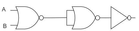
The given electrical network is equivalent to:
A) NOT gate
B) AND gate
C) OR gate
D) NOR gate
Answer
243.6k+ views
Hint: The logic gates form the unit of all the digital systems. The given electrical network represents the negative logic gates included in it. In order to calculate the required output of the given gates, get the output for the one by one and find for the last gate connected. Check it with the gates given in the option.
Complete step by step solution:
In the given electrical network, it represents the NOR gate, NOR gate and the NOT gate connected in series. The two NOR gates function opposite to that of the OR gate and the NOT provides the opposite result to the input. At first the first NOR gate is considered. In which the two inputs $A$ and $B$ are considered but gives the single output. This single output is fed into the other NOR gate. This gate takes only one output and also gives the one output which is opposite to the taken output. The output from the second NOR gate is taken into the NOT gate and gives the required output.
Let us construct the table of the given electrical network.
Hence the end of the NOT gate shows the output of the entire logic gate in the given electrical network. From the table, it is clear that the NOR gate alone for the given input, provides the same result to the whole logic gates in the electrical circuit. Hence the NOR gate is equivalent.
Thus the option (D) is correct.
Note: The logic gates like NAND and the NOR are called as the universal logic gates since they can perform the functions of the other logic gates like AND, OR and NOT. The single input NOR and the NOT gate perform the same functions to that of the NOT gate.
Complete step by step solution:
In the given electrical network, it represents the NOR gate, NOR gate and the NOT gate connected in series. The two NOR gates function opposite to that of the OR gate and the NOT provides the opposite result to the input. At first the first NOR gate is considered. In which the two inputs $A$ and $B$ are considered but gives the single output. This single output is fed into the other NOR gate. This gate takes only one output and also gives the one output which is opposite to the taken output. The output from the second NOR gate is taken into the NOT gate and gives the required output.
Let us construct the table of the given electrical network.
| First input | Second input | NOR gate | NOR gate | Not gate |
| $0$ | $0$ | $1$ | $0$ | $1$ |
| $0$ | $1$ | $0$ | $1$ | $0$ |
| $1$ | $0$ | $0$ | $1$ | $0$ |
| $1$ | $1$ | $0$ | $1$ | $0$ |
Hence the end of the NOT gate shows the output of the entire logic gate in the given electrical network. From the table, it is clear that the NOR gate alone for the given input, provides the same result to the whole logic gates in the electrical circuit. Hence the NOR gate is equivalent.
Thus the option (D) is correct.
Note: The logic gates like NAND and the NOR are called as the universal logic gates since they can perform the functions of the other logic gates like AND, OR and NOT. The single input NOR and the NOT gate perform the same functions to that of the NOT gate.
Recently Updated Pages
JEE Main 2026 Session 2 City Intimation Slip & Exam Date: Expected Date, Download Link
JEE Main 2026 Session 2 Application Form: Reopened Registration, Dates & Fees
JEE Main 2026 Session 2 Registration (Reopened): Last Date, Fees, Link & Process
WBJEE 2026 Registration Started: Important Dates Eligibility Syllabus Exam Pattern
JEE Main 2025-26 Mock Tests: Free Practice Papers & Solutions
JEE Main 2025-26 Experimental Skills Mock Test – Free Practice
Trending doubts
JEE Main 2026: Exam Dates, Session 2 Updates, City Slip, Admit Card & Latest News
Ideal and Non-Ideal Solutions Explained for Class 12 Chemistry
Understanding the Angle of Deviation in a Prism
Understanding Differential Equations: A Complete Guide
Hybridisation in Chemistry – Concept, Types & Applications
Understanding the Electric Field of a Uniformly Charged Ring
Other Pages
CBSE Class 12 Physics Question Paper 2026: Download SET-wise PDF with Answer Key & Analysis
JEE Advanced Marks vs Ranks 2025: Understanding Category-wise Qualifying Marks and Previous Year Cut-offs
JEE Advanced 2026 - Exam Date (Released), Syllabus, Registration, Eligibility, Preparation, and More
Dual Nature of Radiation and Matter Class 12 Physics Chapter 11 CBSE Notes - 2025-26
JEE Advanced Weightage 2025 Chapter-Wise for Physics, Maths and Chemistry
Understanding the Block and Tackle System