


How Do LC Circuits Produce Oscillations?
LC oscillations describe the natural exchange of energy between an inductor (L) and a capacitor (C) connected in a circuit without resistance. This process results in the regular oscillation of electric current and charge in the circuit, which is fundamental in the study of alternating currents and electromagnetic resonance.
Definition and Basic Concept of LC Oscillations
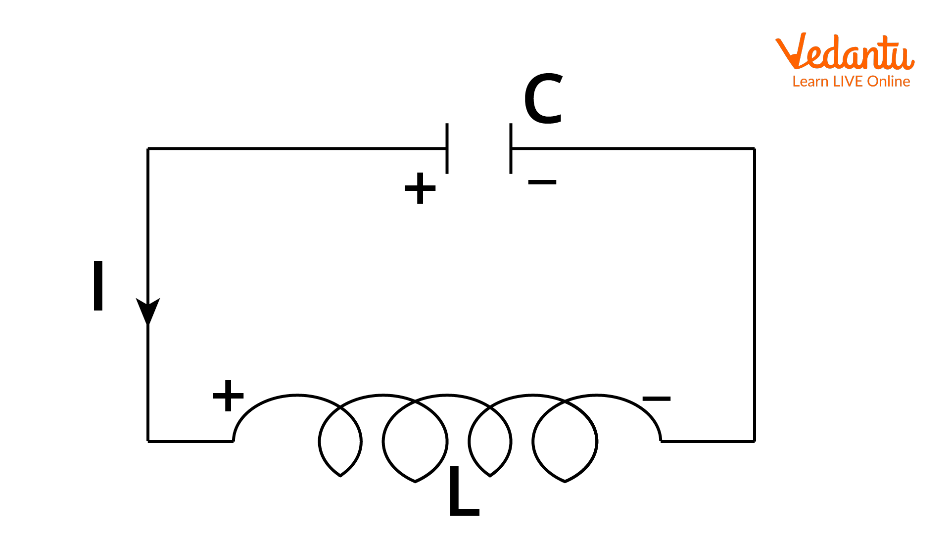
An LC oscillation occurs when a charged capacitor is connected to an inductor, causing the stored energy to transfer back and forth between electric and magnetic fields. The inductor and capacitor are connected in series, forming a closed loop with energy oscillating between the two components.
In the absence of resistance, such as in an ideal LC circuit, energy conservation ensures that the oscillations are undamped and continue indefinitely. The charge and current in the circuit vary sinusoidally with time. This concept is further elaborated in Electromagnetic Induction Revision Notes.
Energy Transfer Mechanism in an LC Circuit
When the circuit is closed, the charged capacitor begins to discharge, transferring its energy into the magnetic field of the inductor as current flows. When the capacitor is fully discharged, the inductor's magnetic field holds the maximum energy. The inductor then maintains the current, recharging the capacitor with opposite polarity.
This cyclical process leads to continuous and sinusoidal oscillations of both charge on the capacitor and the current in the circuit. At any instant, the total energy remains constant, but its form transfers between the electric field of the capacitor and the magnetic field of the inductor.
Differential Equation Governing LC Oscillations
The dynamics of LC oscillations are described by Kirchhoff’s voltage law applied to the series LC circuit. The sum of the voltages across the capacitor and inductor is zero at all times:
$V_C + V_L = 0$
Where $V_C = \dfrac{q}{C}$ and $V_L = L\dfrac{dI}{dt}$ with $I = -\dfrac{dq}{dt}$.
The equation becomes:
$\dfrac{q}{C} + L\dfrac{d^2q}{dt^2} = 0$
Rearranging gives:
$\dfrac{d^2q}{dt^2} + \dfrac{1}{LC}q = 0$
This is the standard equation for simple harmonic motion, with the charge oscillating sinusoidally at a natural angular frequency $\omega$:
$\omega = \dfrac{1}{\sqrt{LC}}$
Frequency of LC Oscillations
The frequency of oscillation $f$ in an LC circuit is derived from the angular frequency $\omega$ as follows:
$f = \dfrac{\omega}{2\pi} = \dfrac{1}{2\pi\sqrt{LC}}$
Here, $L$ is measured in henry (H) and $C$ in farad (F). The resulting frequency is in hertz (Hz). This formula is key for calculations in JEE problems and helps analyze circuits in radio, television, and communication technologies. Further understanding of such circuits can be gained from the RC Circuit Overview.
Qualitative Treatment of LC Oscillations
In qualitative treatment, the focus is on the energy exchange process without detailed mathematical derivation. The system repeatedly shifts energy between electric potential energy in the capacitor and magnetic energy in the inductor, leading to undamped, periodic oscillations in ideal conditions.
| Mechanical System | LC Circuit Analogy |
|---|---|
| Mass (m) | Inductance (L) |
| Spring constant (k) | $1/C$ |
| Potential energy $(\dfrac{1}{2}kx^2)$ | Capacitor energy $(\dfrac{1}{2}CV^2)$ |
| Kinetic energy $(\dfrac{1}{2}mv^2)$ | Inductor energy $(\dfrac{1}{2}LI^2)$ |
Both current and charge in the LC circuit exhibit sinusoidal variation over time. Maximum current occurs when the capacitor is fully discharged, and maximum charge is reached when current is zero. A similar analogy exists with mechanical oscillations in a spring-mass system.
Applications of LC Oscillations
LC oscillators are widely used in electronic devices and communication systems. Applications include radio transmitters, television receivers, frequency filters, and pulse-generating circuits. Understanding these oscillations is fundamental in electronic circuit design and signal processing, and can be related to the concepts discussed in Electromagnetic Spectrum Explained.
- Radio and TV signal selection circuits
- Resonant circuits in communication systems
- Oscillator circuits in clocks and watches
- Pulse-generating networks
- Filters and frequency-selective amplifiers
Solved Example: Frequency Calculation in an LC Circuit
Given a capacitor of $2\ \mu\text{F}$ and an inductor of $0.5\ \text{H}$, the frequency of oscillation can be calculated as follows:
$f = \dfrac{1}{2\pi\sqrt{LC}} = \dfrac{1}{2\pi\sqrt{0.5 \times 2 \times 10^{-6}}}$
$= \dfrac{1}{2\pi \times 1 \times 10^{-3}} \approx 159\ \text{Hz}$
Characteristic Features of LC Oscillations
- Oscillations occur only with negligible resistance
- Total energy is conserved and switches forms
- Current and charge follow a sinusoidal pattern
- No external energy source is required after initiation
Key Equations and Revision Points
- Charge: $q(t) = Q_0 \cos(\omega t + \phi)$
- Current: $I(t) = -Q_0 \omega \sin(\omega t + \phi)$
- Frequency: $f = \dfrac{1}{2\pi\sqrt{LC}}$
- Capacitor energy: $\dfrac{1}{2}CV^2$
- Inductor energy: $\dfrac{1}{2}LI^2$
Related Circuits and Further Reading
LC circuits are foundational in the study of alternating currents, electromagnetic induction, and resonance. Additional details on related topics can be found in Understanding Current Electricity.
For comparative understanding, study the difference between LC, RC, and RL circuits by referring to their role in circuit analysis and time-dependent behavior. These differences are crucial in both theory and practical applications. To explore thermodynamic parallels, visit Fundamentals of Thermodynamics.
FAQs on Understanding LC Oscillations in Physics
1. What is LC oscillation?
LC oscillation refers to the continuous flow of electrical energy between a capacitor and an inductor in an ideal LC circuit.
Key points:
- An LC oscillator consists of a capacitor (C) and an inductor (L) connected in series or parallel.
- Energy shifts between the electric field (capacitor) and magnetic field (inductor).
- No external resistance is assumed in ideal LC circuits.
- It produces undamped, sinusoidal oscillations at a natural frequency.
2. Explain the working principle of an LC circuit.
The working principle of an LC circuit is based on energy exchange between the capacitor and inductor.
Main steps:
- Initially, the charged capacitor releases its energy, creating current through the inductor.
- The inductor stores this energy in its magnetic field as the capacitor discharges.
- When the capacitor is fully discharged, the inductor’s magnetic field collapses, recharging the capacitor with opposite polarity.
- This process repeats, forming oscillating current.
3. Derive the expression for frequency of oscillations in an LC circuit.
The frequency (f) of LC oscillations is given by the formula:
Derivation summary:
- Apply Kirchoff’s law: V_L + V_C = 0 (for ideal LC circuit).
- This leads to the differential equation: L (d²q/dt²) + (1/C)q = 0.
- Its solution is simple harmonic: q = Q cos(ωt + φ) with ω = 1/√(LC).
- So, frequency f = ω / (2π) = 1 / (2π√(LC)).
4. What are the conditions necessary for sustained oscillations in an LC circuit?
Sustained oscillations in an LC circuit require certain ideal conditions.
Essential conditions:
- No resistive component (R = 0), so no energy loss as heat.
- The circuit should be isolated from energy dissipation sources.
- Capacitor and inductor must both be ideal (no leakage, no core losses).
5. What is the energy transformation that takes place in an LC oscillator?
Energy in an LC oscillator continuously shifts between two forms.
Energy transformation steps:
- Electric energy stored in the capacitor’s electric field.
- As the capacitor discharges, energy is transferred as magnetic energy in the inductor’s magnetic field.
- The process reverses, and energy flows back to the capacitor.
6. State the expression for total energy in an LC circuit.
Total energy (E) in an LC circuit remains constant and equals the sum of energies in the capacitor and inductor.
Expression:
E = (1/2)CV² + (1/2)LI²
where:
- C = Capacitance
- V = Voltage across capacitor
- L = Inductance
- I = Current in the inductor
7. What are damped and undamped oscillations? How do they relate to LC circuits?
Undamped oscillations have constant amplitude, while damped oscillations gradually decrease in amplitude.
Relation to LC circuits:
- In ideal LC circuits (no resistance), oscillations are undamped.
- If resistance is present (as in an LCR circuit), oscillations are damped, losing energy over time.
8. What is the role of the inductor in LC oscillations?
The inductor in an LC circuit stores energy in its magnetic field and opposes sudden changes in current.
Main functions:
- It provides magnetic energy storage.
- Facilitates the transfer of energy to and from the capacitor.
- Controls the timing and frequency of the oscillation by its inductance value.
9. Describe the resonance condition in an LC circuit.
Resonance in an LC circuit occurs when the circuit oscillates at its natural frequency, causing maximum current flow.
Explanation:
- At resonance, the inductive and capacitive reactances are equal and opposite.
- This cancels their effects, making total reactance zero.
- Current reaches its maximum (in a parallel circuit) or voltage is maximized (in a series circuit).
10. Why is there no energy loss in an ideal LC circuit?
An ideal LC circuit lacks resistance and other dissipative elements, so energy is not converted to heat.
Reasons for no energy loss:
- Only inductance and capacitance are present.
- No resistor means no power loss as heat.
- All energy oscillates between the capacitor and inductor.
11. What is the equation of charge in an LC oscillator as a function of time?
The time-dependent charge (q) in an LC oscillator follows simple harmonic motion.
Equation:
q(t) = Q cos(ωt + φ)
where:
- Q = maximum charge (initial charge on the capacitor)
- ω = angular frequency = 1/√(LC)
- t = time
- φ = phase constant (depends on initial conditions)
12. Give a practical application of LC oscillations.
LC oscillations are widely used in tuning circuits for radio, television, and communication devices.
Application example:
- Radio tuners use LC circuits to select specific broadcast frequencies (resonance).
- Oscillators in transmitters and receivers rely on LC resonance for stable frequencies.